sensor TOYOTA CAMRY V20 1986 Service Information
[x] Cancel search | Manufacturer: TOYOTA, Model Year: 1986, Model line: CAMRY V20, Model: TOYOTA CAMRY V20 1986Pages: 2389, PDF Size: 84.44 MB
Page 1344 of 2389
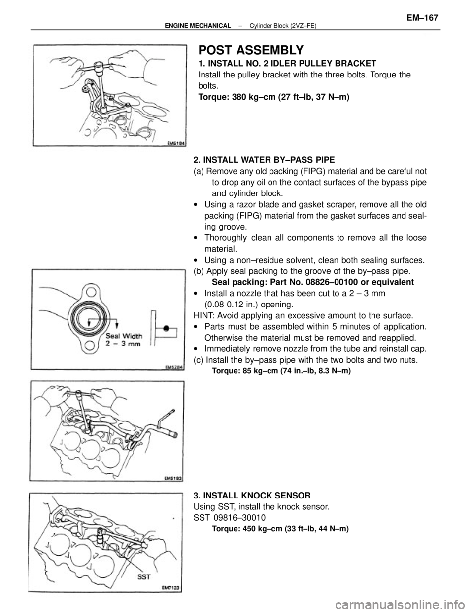
2. INSTALL WATER BY±PASS PIPE
(a) Remove any old packing (FIPG) material and be careful not
to drop any oil on the contact surfaces of the bypass pipe
and cylinder block.
wUsing a razor blade and gasket scraper, remove all the old
packing (FIPG) material from the gasket surfaces and seal-
ing groove.
wThoroughly clean all components to remove all the loose
material.
wUsing a non±residue solvent, clean both sealing surfaces.
(b) Apply seal packing to the groove of the by±pass pipe.
Seal packing: Part No. 08826±00100 or equivalent
wInstall a nozzle that has been cut to a 2 ± 3 mm
(0.08 0.12 in.) opening.
HINT: Avoid applying an excessive amount to the surface.
wParts must be assembled within 5 minutes of application.
Otherwise the material must be removed and reapplied.
wImmediately remove nozzle from the tube and reinstall cap.
(c) Install the by±pass pipe with the two bolts and two nuts.
Torque: 85 kg±cm (74 in.±lb, 8.3 N±m)
POST ASSEMBLY
1. INSTALL NO. 2 IDLER PULLEY BRACKET
Install the pulley bracket with the three bolts. Torque the
bolts.
Torque: 380 kg±cm (27 ft±Ib, 37 N±m)
3. INSTALL KNOCK SENSOR
Using SST, install the knock sensor.
SST 09816±30010
Torque: 450 kg±cm (33 ft±lb, 44 N±m)
± ENGINE MECHANICALCylinder Block (2VZ±FE)EM±167
Page 1837 of 2389
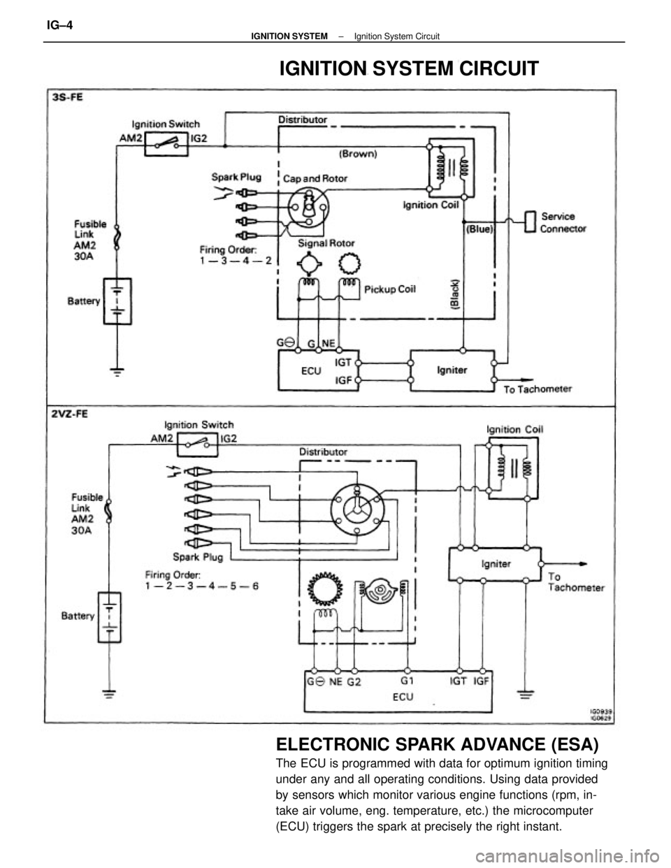
ELECTRONIC SPARK ADVANCE (ESA)
The ECU is programmed with data for optimum ignition timing
under any and all operating conditions. Using data provided
by sensors which monitor various engine functions (rpm, in-
take air volume, eng. temperature, etc.) the microcomputer
(ECU) triggers the spark at precisely the right instant.
IGNITION SYSTEM CIRCUIT
± IGNITION SYSTEMIgnition System CircuitIG±4
Page 1861 of 2389
PRECAUTIONS FOR VEHICLES EQUIPPED WITH A
CATALYTIC CONVERTER
CAUTION: If large amounts of unburned gasoline flow into the converter, it may overheat
and create a fire hazard. To prevent this, observe the following precautions and
explain them to your customer.
1. Use only unleaded gasoline.
2. Avoid prolonged idling.
Avoid running the engine at idle speed for more than 20
minutes.
3. Avoid spark jump test.
(a) Spark jump test only when absolutely necessary. Perform this test as rapidly as pos-
sible.
(b) While testing, never race the engine.
4. Avoid prolonged engine compression measurement.
Engine compression tests must be made as rapidly as possible.
5. Do not run engine when fuel tank is nearly empty.
This may cause the engine to misfire and create an extra
load on the converter.
6. Avoid coasting with ignition turned off and prolonged braking.
7. Do not dispose of used catalyst along with parts contaminated with gasoline or oil.(f) When steam cleaning an engine, protect the distribu-
tor, air filter and VCV from water.
(g) Never use an impact wrench to remove or install tem-
perature switches or temperature sensors.
(h) When checking continuity at the wire connector, insert
the tester probe carefully to prevent terminals from
bending.
(i) When using a vacuum gauge, never force the hose
onto a connector that is too large. Use a step±down
adapter instead. Once the hose has been stretched,
it may leak.
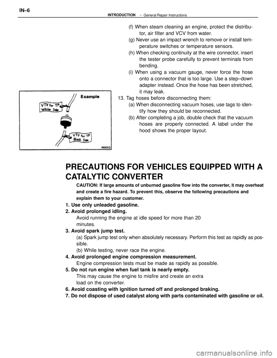
13. Tag hoses before disconnecting them:
(a) When disconnecting vacuum hoses, use tags to iden-
tify how they should be reconnected.
(b) After completing a job, double check that the vacuum
hoses are properly connected. A label under the
hood shows the proper layout.
± INTRODUCTIONIN±6General Repair Instructions
Page 1862 of 2389
PRECAUTIONS FOR VEHICLES EQUIPPED WITH A
CATALYTIC CONVERTER
CAUTION: If large amounts of unburned gasoline flow into the converter, it may overheat
and create a fire hazard. To prevent this, observe the following precautions and
explain them to your customer.
1. Use only unleaded gasoline.
2. Avoid prolonged idling.
Avoid running the engine at idle speed for more than 20
minutes.
3. Avoid spark jump test.
(a) Spark jump test only when absolutely necessary. Perform this test as rapidly as pos-
sible.
(b) While testing, never race the engine.
4. Avoid prolonged engine compression measurement.
Engine compression tests must be made as rapidly as possible.
5. Do not run engine when fuel tank is nearly empty.
This may cause the engine to misfire and create an extra
load on the converter.
6. Avoid coasting with ignition turned off and prolonged braking.
7. Do not dispose of used catalyst along with parts contaminated with gasoline or oil.(f) When steam cleaning an engine, protect the distribu-
tor, air filter and VCV from water.
(g) Never use an impact wrench to remove or install tem-
perature switches or temperature sensors.
(h) When checking continuity at the wire connector, insert
the tester probe carefully to prevent terminals from
bending.
(i) When using a vacuum gauge, never force the hose
onto a connector that is too large. Use a step±down
adapter instead. Once the hose has been stretched,
it may leak.
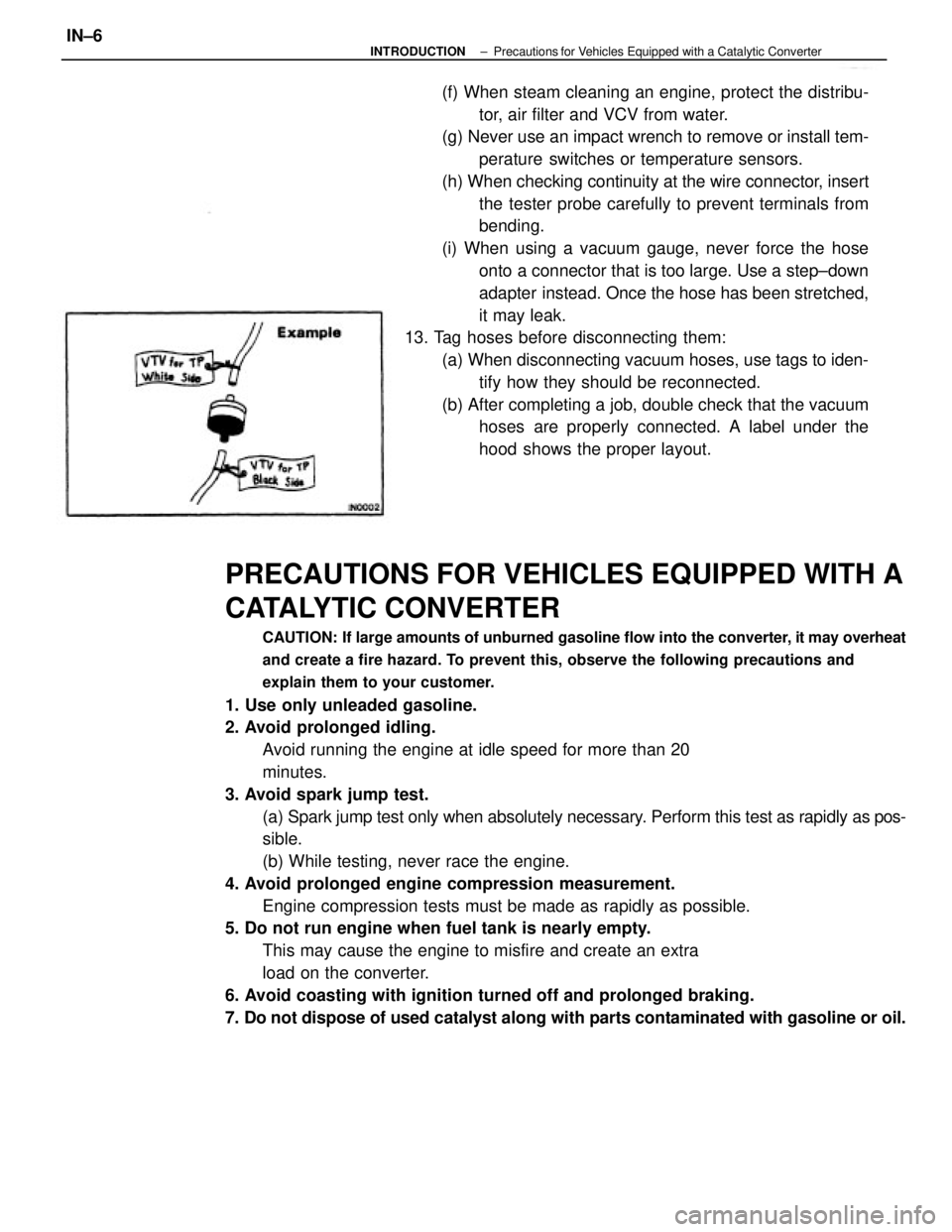
13. Tag hoses before disconnecting them:
(a) When disconnecting vacuum hoses, use tags to iden-
tify how they should be reconnected.
(b) After completing a job, double check that the vacuum
hoses are properly connected. A label under the
hood shows the proper layout.
± INTRODUCTIONPrecautions for Vehicles Equipped with a Catalytic ConverterIN±6
Page 2222 of 2389
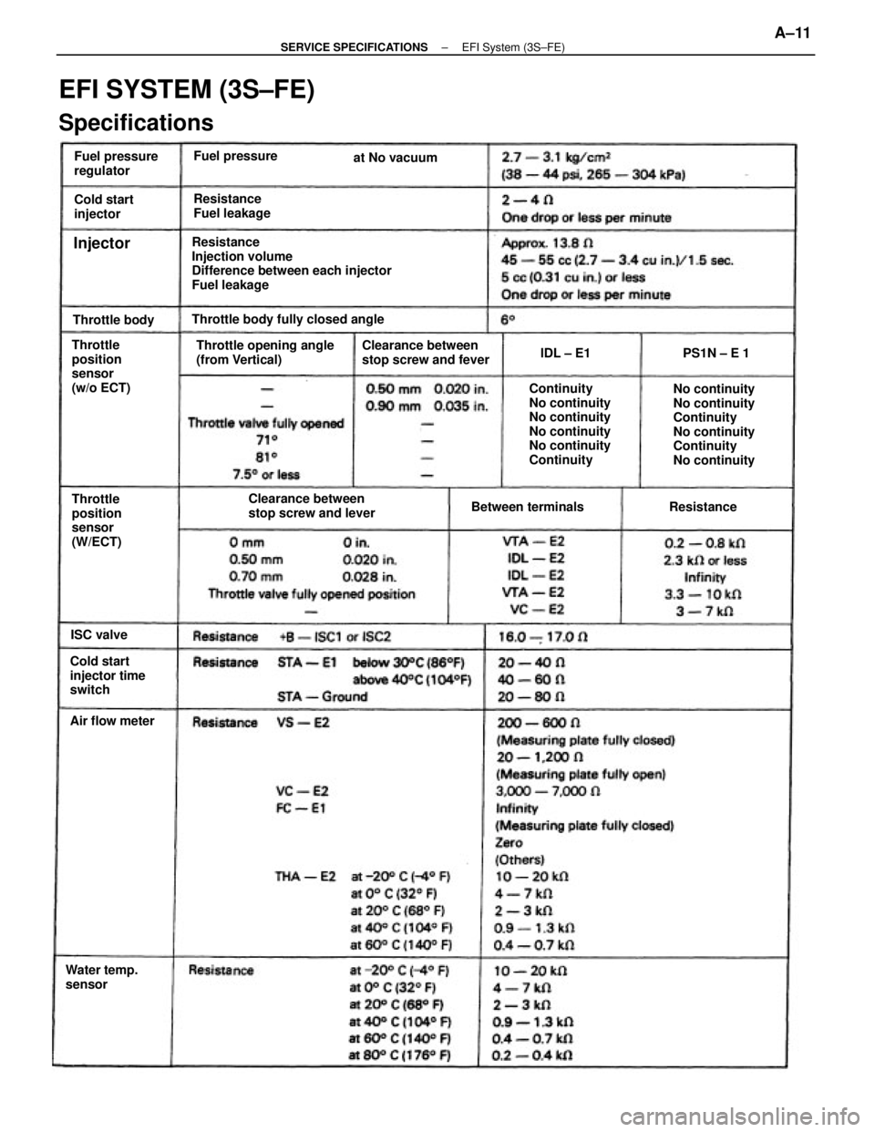
Resistance
Injection volume
Difference between each injector
Fuel leakage
EFI SYSTEM (3S±FE)
Specifications
No continuity
No continuity
Continuity
No continuity
Continuity
No continuity Continuity
No continuity
No continuity
No continuity
No continuity
Continuity Throttle opening angle
(from Vertical)Clearance between
stop screw and fever
Clearance between
stop screw and lever Throttle
position
sensor
(w/o ECT)Throttle body fully closed angle
Cold start
injector time
switchThrottle
position
sensor
(W/ECT)Fuel pressure
regulator
Resistance
Fuel leakage
Water temp.
sensorBetween terminals Cold start
injector
Air flow meterFuel pressure
Throttle bodyat No vacuum
ResistancePS1N ± E 1
ISC valvelDL ± E1
Injector
± SERVICE SPECIFICATIONSEFI System (3S±FE)A±11
Page 2223 of 2389
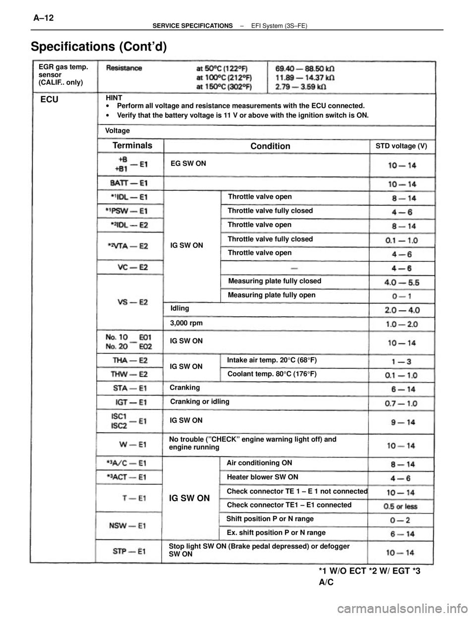
HINT
wPerform all voltage and resistance measurements with the ECU connected.
wVerify that the battery voltage is 11 V or above with the ignition switch is ON.
Stop light SW ON (Brake pedal depressed) or defogger
SW ONNo trouble (ºCHECKº engine warning light off) and
engine running
Check connector TE 1 ± E 1 not connected
Specifications (Cont'd)
Check connector TE1 ± E1 connected
*1 W/O ECT *2 W/ EGT *3
A/C
EGR gas temp.
sensor
(CALIF.. only)
Ex. shift position P or N rangeIntake air temp. 205C (685F) Measuring plate fully closed
Coolant temp. 805C (1765F)
Shift position P or N rangeMeasuring plate fully open Throttle valve fully closed
Throttle valve fully closed
Heater blower SW ON Air conditioning ONThrottle valve open
Throttle valve open
Throttle valve open
Cranking or idlingSTD voltage (V)
3,000 rpmEG SW ON
IG SW ON IG SW ONIG SW ONIG SW ON
IG SW ON
Cranking
Terminals
Condition
Voltage
Idling
ECU
± SERVICE SPECIFICATIONSEFI System (3S±FE)A±12
Page 2226 of 2389
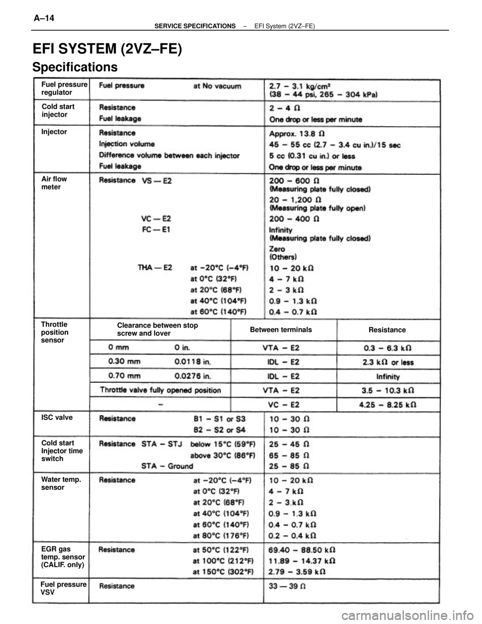
EFI SYSTEM (2VZ±FE)
Specifications
Clearance between stop
screw and lover
EGR gas
temp. sensor
(CALIF. only)Cold start
Injector time
switch Fuel pressure
regulator
Fuel pressure
VSVWater temp.
sensor Throttle
position
sensorBetween terminals Cold start
injector
Air flow
meter
Resistance
ISC valve Injector
± SERVICE SPECIFICATIONSEFI System (2VZ±FE)A±14
Page 2227 of 2389
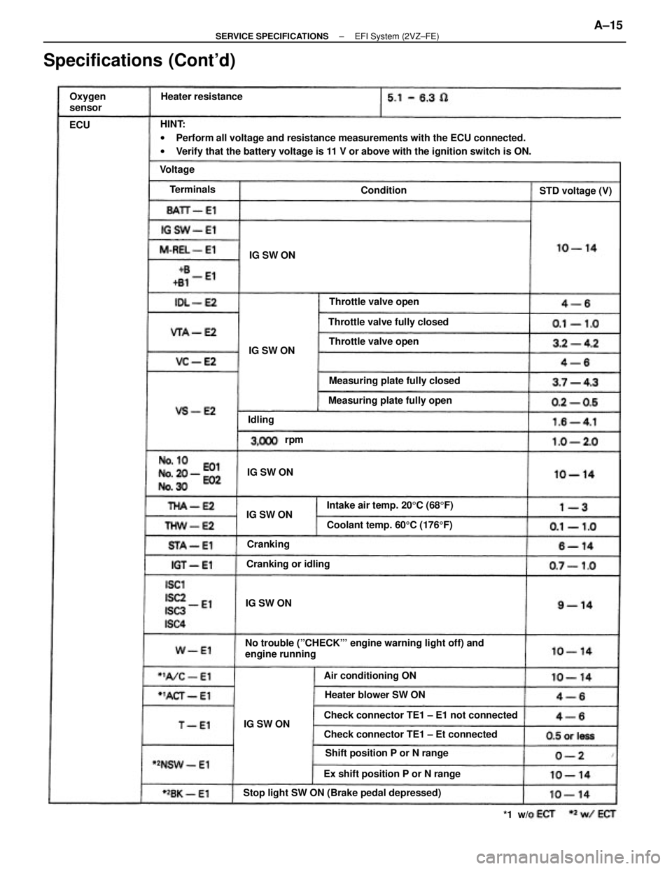
HINT:
wPerform all voltage and resistance measurements with the ECU connected.
wVerify that the battery voltage is 11 V or above with the ignition switch is ON.
No trouble (ºCHECKº' engine warning light off) and
engine running
Specifications (Cont'd)
Stop light SW ON (Brake pedal depressed)Check connector TE1 ± E1 not connected
Check connector TE1 ± Et connected
Shift position P or N range
Ex shift position P or N rangeIntake air temp. 205C (685F) Measuring plate fully closed
Coolant temp. 605C (1765F) Measuring plate fully open Throttle valve fully closed
Heater blower SW ON Air conditioning ONThrottle valve open
Throttle valve open
Cranking or idling Heater resistance
STD voltage (V) Oxygen
sensor
IG SW ON
IG SW ONIG SW ON
IG SW ONIG SW ON
IG SW ONCranking Terminals
Condition Voltage
Idling
*1 w/ rpm ECU
± SERVICE SPECIFICATIONSEFI System (2VZ±FE)A±15
Page 2267 of 2389
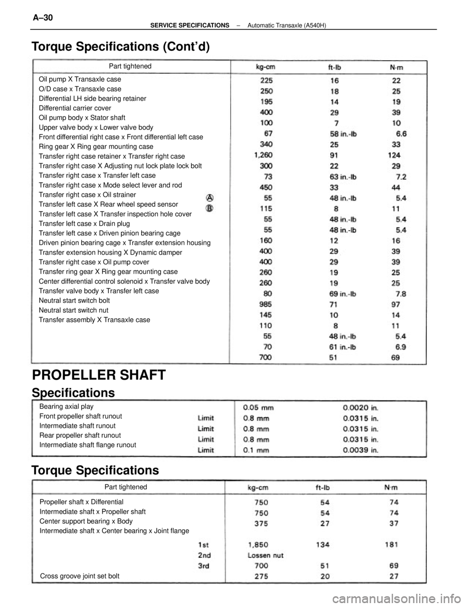
Oil pump X Transaxle case
O/D case x Transaxle case
Differential LH side bearing retainer
Differential carrier cover
Oil pump body x Stator shaft
Upper valve body x Lower valve body
Front differential right case x Front differential left case
Ring gear X Ring gear mounting case
Transfer right case retainer x Transfer right case
Transfer right case X Adjusting nut lock plate lock bolt
Transfer right case x Transfer left case
Transfer right case x Mode select lever and rod
Transfer right case x Oil strainer
Transfer left case X Rear wheel speed sensor
Transfer left case X Transfer inspection hole cover
Transfer left case x Drain plug
Transfer left case x Driven pinion bearing cage
Driven pinion bearing cage x Transfer extension housing
Transfer extension housing X Dynamic damper
Transfer right case x Oil pump cover
Transfer ring gear X Ring gear mounting case
Center differential control solenoid x Transfer valve body
Transfer valve body x Transfer left case
Neutral start switch bolt
Neutral start switch nut
Transfer assembly X Transaxle case
Propeller shaft x Differential
Intermediate shaft x Propeller shaft
Center support bearing x Body
Intermediate shaft x Center bearing x Joint flange Bearing axial play
Front propeller shaft runout
Intermediate shaft runout
Rear propeller shaft runout
Intermediate shaft flange runout
PROPELLER SHAFT
Specifications Torque Specifications (Cont'd)
Torque Specifications
Cross groove joint set boltPart tightenedPart tightened
± SERVICE SPECIFICATIONSAutomatic Transaxle (A540H)A±30
Page 2268 of 2389
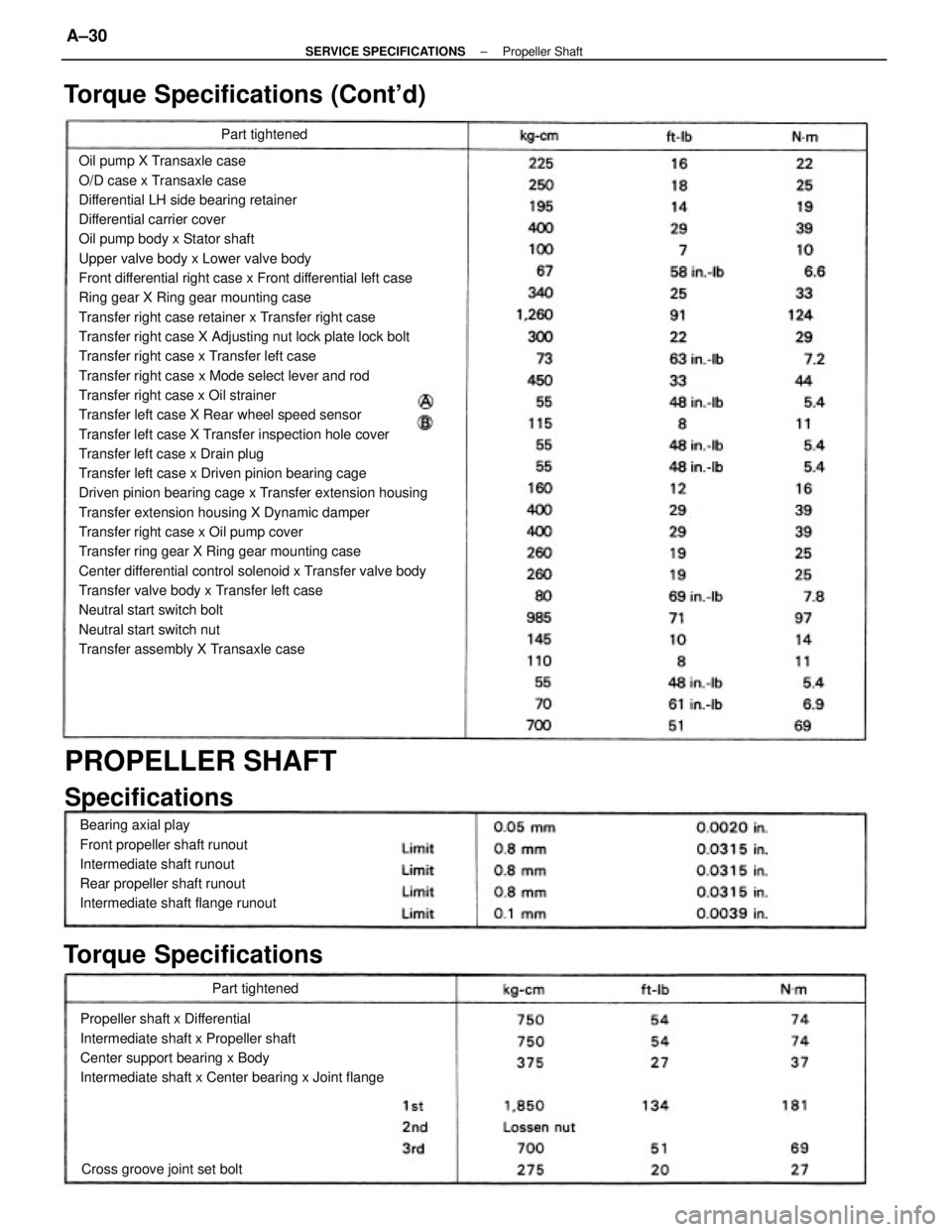
Oil pump X Transaxle case
O/D case x Transaxle case
Differential LH side bearing retainer
Differential carrier cover
Oil pump body x Stator shaft
Upper valve body x Lower valve body
Front differential right case x Front differential left case
Ring gear X Ring gear mounting case
Transfer right case retainer x Transfer right case
Transfer right case X Adjusting nut lock plate lock bolt
Transfer right case x Transfer left case
Transfer right case x Mode select lever and rod
Transfer right case x Oil strainer
Transfer left case X Rear wheel speed sensor
Transfer left case X Transfer inspection hole cover
Transfer left case x Drain plug
Transfer left case x Driven pinion bearing cage
Driven pinion bearing cage x Transfer extension housing
Transfer extension housing X Dynamic damper
Transfer right case x Oil pump cover
Transfer ring gear X Ring gear mounting case
Center differential control solenoid x Transfer valve body
Transfer valve body x Transfer left case
Neutral start switch bolt
Neutral start switch nut
Transfer assembly X Transaxle case
Propeller shaft x Differential
Intermediate shaft x Propeller shaft
Center support bearing x Body
Intermediate shaft x Center bearing x Joint flange Bearing axial play
Front propeller shaft runout
Intermediate shaft runout
Rear propeller shaft runout
Intermediate shaft flange runout
PROPELLER SHAFT
Specifications Torque Specifications (Cont'd)
Torque Specifications
Cross groove joint set boltPart tightenedPart tightened
± SERVICE SPECIFICATIONSPropeller ShaftA±30