sensor TOYOTA CAMRY V20 1986 Service Information
[x] Cancel search | Manufacturer: TOYOTA, Model Year: 1986, Model line: CAMRY V20, Model: TOYOTA CAMRY V20 1986Pages: 2389, PDF Size: 84.44 MB
Page 1114 of 2389
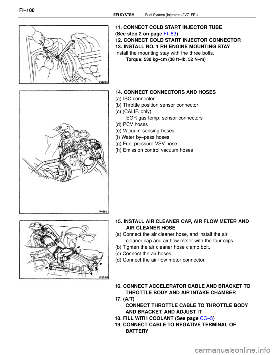
16. CONNECT ACCELERATOR CABLE AND BRACKET TO
THROTTLE BODY AND AIR INTAKE CHAMBER
17. (A/T)
CONNECT THROTTLE CABLE TO THROTTLE BODY
AND BRACKET, AND ADJUST IT
18. FILL WITH COOLANT (See page CO±5)
19. CONNECT CABLE TO NEGATIVE TERMINAL OF
BATTERY 14. CONNECT CONNECTORS AND HOSES
(a) ISC connector
(b) Throttle position sensor connector
(c) (CALIF. only)
EGR gas temp. sensor connectors
(d) PCV hoses
(e) Vacuum sensing hoses
(f) Water by±pass hoses
(g) Fuel pressure VSV hose
(h) Emission control vacuum hoses
15. INSTALL AIR CLEANER CAP, AIR FLOW METER AND
AIR CLEANER HOSE
(a) Connect the air cleaner hose, and install the air
cleaner cap and air flow meter with the four clips.
(b) Tighten the air cleaner hose clamp bolt.
(c) Connect the air hoses.
(d) Connect the air flow meter connector. 11. CONNECT COLD START INJECTOR TUBE
(See step 2 on page FI±83)
12. CONNECT COLD START INJECTOR CONNECTOR
13. INSTALL NO. 1 RH ENGINE MOUNTING STAY
Install the mounting stay with the three bolts.
Torque: 530 kg±cm (38 ft±Ib, 52 N±m)
± EFI SYSTEMFuel System (Injectors (2VZ±FE))FI±100
Page 1120 of 2389
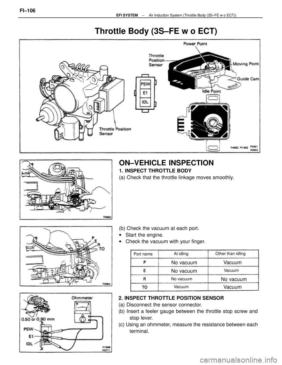
2. INSPECT THROTTLE POSITION SENSOR
(a) Disconnect the sensor connector.
(b) Insert a feeler gauge between the throttle stop screw and
stop lever.
(c) Using an ohmmeter, measure the resistance between each
terminal.
ON±VEHICLE INSPECTION
1. INSPECT THROTTLE BODY
(a) Check that the throttle linkage moves smoothly.
(b) Check the vacuum at each port.
wStart the engine.
wCheck the vacuum with your finger.
Throttle Body (3S±FE w o ECT)
Other than idling
No vacuum
No vacuum No vacuum
No vacuum Port nameAt idling
Vacuum
Vacuum
VacuumVacuum
± EFI SYSTEMAir Induction System (Throttle Body (3S±FE w o ECT))FI±106
Page 1121 of 2389
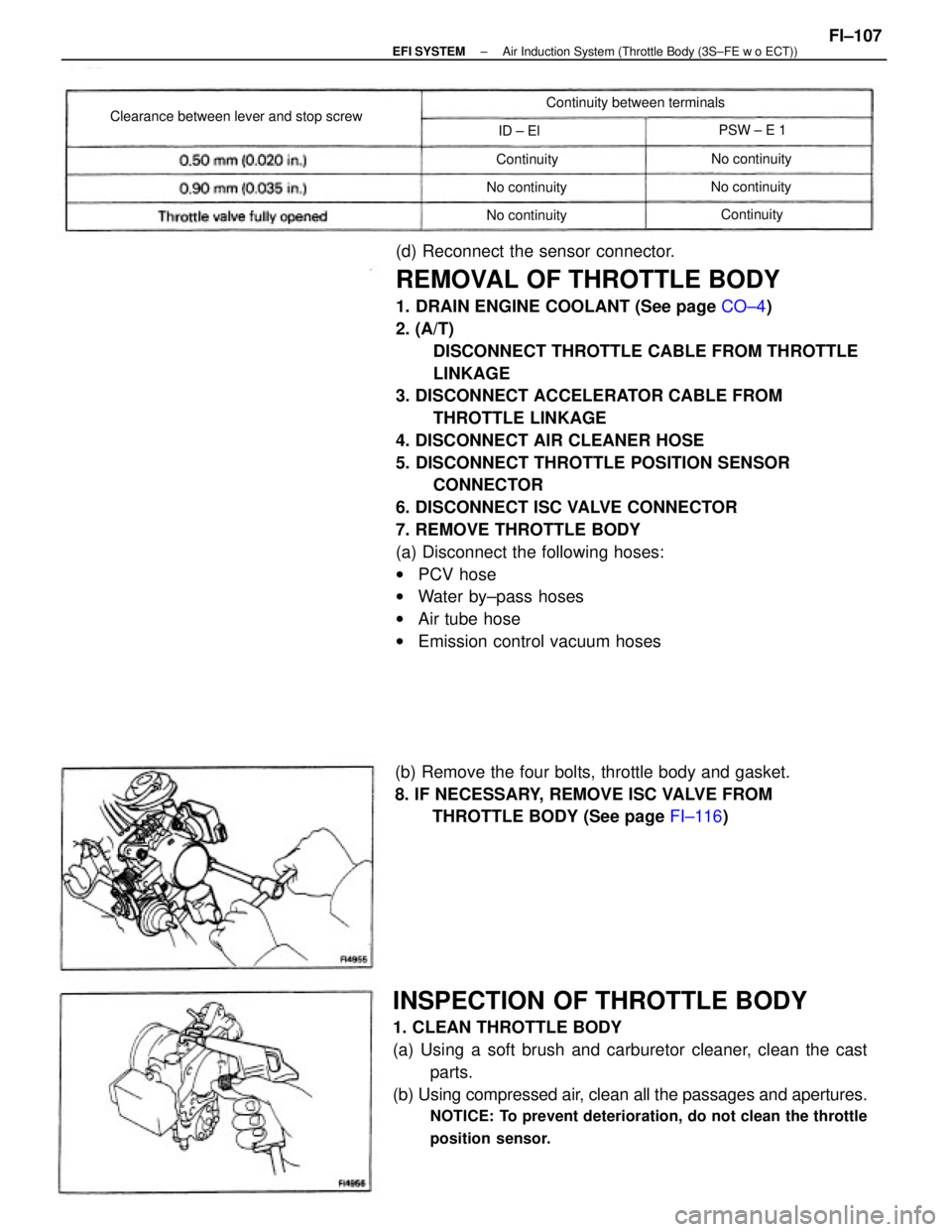
(d) Reconnect the sensor connector.
REMOVAL OF THROTTLE BODY
1. DRAIN ENGINE COOLANT (See page CO±4)
2. (A/T)
DISCONNECT THROTTLE CABLE FROM THROTTLE
LINKAGE
3. DISCONNECT ACCELERATOR CABLE FROM
THROTTLE LINKAGE
4. DISCONNECT AIR CLEANER HOSE
5. DISCONNECT THROTTLE POSITION SENSOR
CONNECTOR
6. DISCONNECT ISC VALVE CONNECTOR
7. REMOVE THROTTLE BODY
(a) Disconnect the following hoses:
wPCV hose
wWater by±pass hoses
wAir tube hose
wEmission control vacuum hoses
INSPECTION OF THROTTLE BODY
1. CLEAN THROTTLE BODY
(a) Using a soft brush and carburetor cleaner, clean the cast
parts.
(b) Using compressed air, clean all the passages and apertures.
NOTICE: To prevent deterioration, do not clean the throttle
position sensor.
(b) Remove the four bolts, throttle body and gasket.
8. IF NECESSARY, REMOVE ISC VALVE FROM
THROTTLE BODY (See page FI±116)
Clearance between lever and stop screwContinuity between terminals
No continuity
No continuity
No continuity
No continuityPSW ± E 1
Continuity
Continuity ID ± El
± EFI SYSTEMAir Induction System (Throttle Body (3S±FE w o ECT))FI±107
Page 1122 of 2389
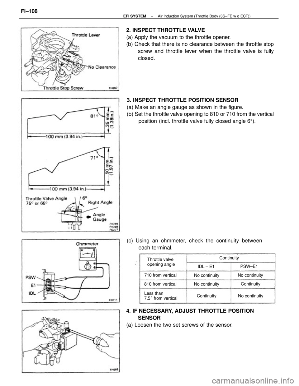
3. INSPECT THROTTLE POSITION SENSOR
(a) Make an angle gauge as shown in the figure.
(b) Set the throttle valve opening to 810 or 710 from the vertical
position (incl. throttle valve fully closed angle 65). 2. INSPECT THROTTLE VALVE
(a) Apply the vacuum to the throttle opener.
(b) Check that there is no clearance between the throttle stop
screw and throttle lever when the throttle valve is fully
closed.
4. IF NECESSARY, ADJUST THROTTLE POSITION
SENSOR
(a) Loosen the two set screws of the sensor.(c) Using an ohmmeter, check the continuity between
each terminal.
Less than
7.5° from vertical Throttle valve
opening angle
710 from vertical
810 from verticalNo continuity
No continuity
No continuity
No continuityContinuity
ContinuityPSW±E1 Continuity
IDL ± E1
± EFI SYSTEMAir Induction System (Throttle Body (3S±FE w o ECT))FI±108
Page 1123 of 2389
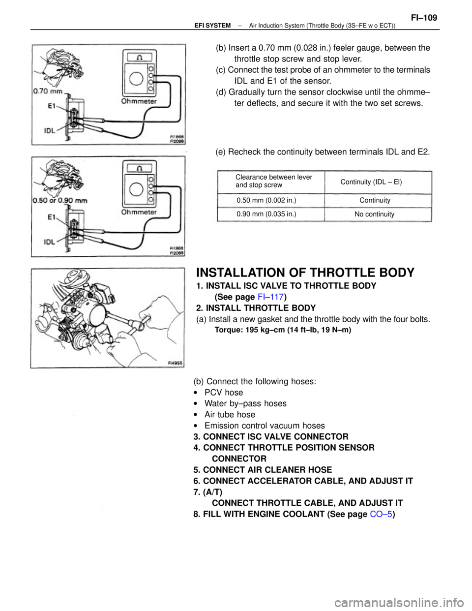
(b) Connect the following hoses:
wPCV hose
wWater by±pass hoses
wAir tube hose
wEmission control vacuum hoses
3. CONNECT ISC VALVE CONNECTOR
4. CONNECT THROTTLE POSITION SENSOR
CONNECTOR
5. CONNECT AIR CLEANER HOSE
6. CONNECT ACCELERATOR CABLE, AND ADJUST IT
7. (A/T)
CONNECT THROTTLE CABLE, AND ADJUST IT
8. FILL WITH ENGINE COOLANT (See page CO±5)
INSTALLATION OF THROTTLE BODY
1. INSTALL ISC VALVE TO THROTTLE BODY
(See page FI±117)
2. INSTALL THROTTLE BODY
(a) Install a new gasket and the throttle body with the four bolts.
Torque: 195 kg±cm (14 ft±Ib, 19 N±m)
(b) Insert a 0.70 mm (0.028 in.) feeler gauge, between the
throttle stop screw and stop lever.
(c) Connect the test probe of an ohmmeter to the terminals
IDL and E1 of the sensor.
(d) Gradually turn the sensor clockwise until the ohmme±
ter deflects, and secure it with the two set screws.
(e) Recheck the continuity between terminals IDL and E2.
Clearance between lever
and stop screwContinuity (IDL ± El)
0.90 mm (0.035 in.) 0.50 mm (0.002 in.)
No continuityContinuity
± EFI SYSTEMAir Induction System (Throttle Body (3S±FE w o ECT))FI±109
Page 1124 of 2389
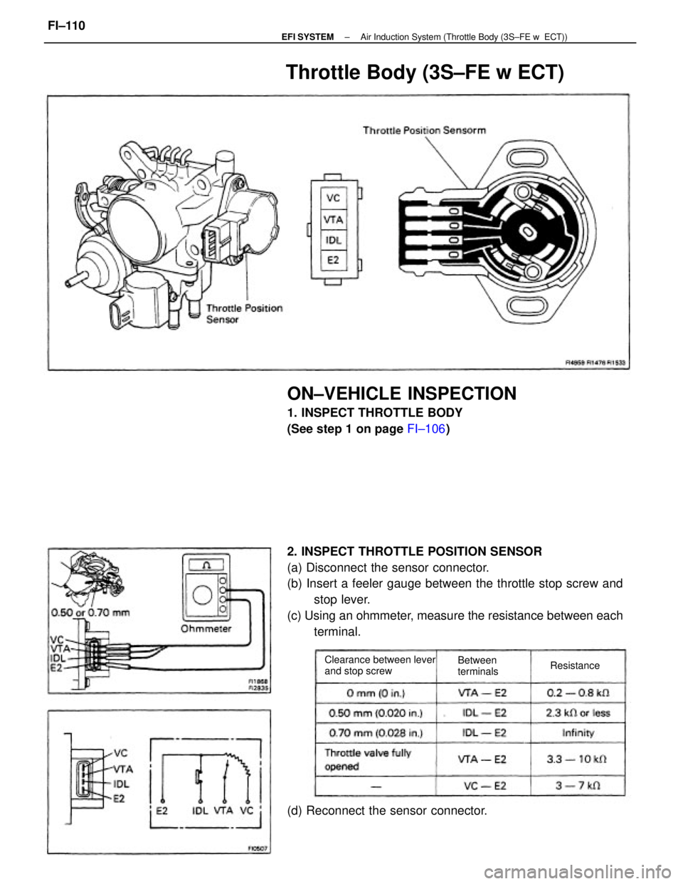
2. INSPECT THROTTLE POSITION SENSOR
(a) Disconnect the sensor connector.
(b) Insert a feeler gauge between the throttle stop screw and
stop lever.
(c) Using an ohmmeter, measure the resistance between each
terminal.
ON±VEHICLE INSPECTION
1. INSPECT THROTTLE BODY
(See step 1 on page FI±106)
Throttle Body (3S±FE w ECT)
(d) Reconnect the sensor connector.
Clearance between lever
and stop screwBetween
terminalsResistance
± EFI SYSTEMAir Induction System (Throttle Body (3S±FE w ECT))FI±110
Page 1125 of 2389
REMOVAL OF THROTTLE BODY
(See page FI±107)
INSPECTION OF THROTTLE BODY
1. CLEAN THROTTLE BODY
(See step 1 on page FI±107)
2. INSPECT THROTTLE VALVE
(See step 2 on page FI±108)
3. INSPECT THROTTLE POSITION SENSOR
(See step 2 on page FI±110)
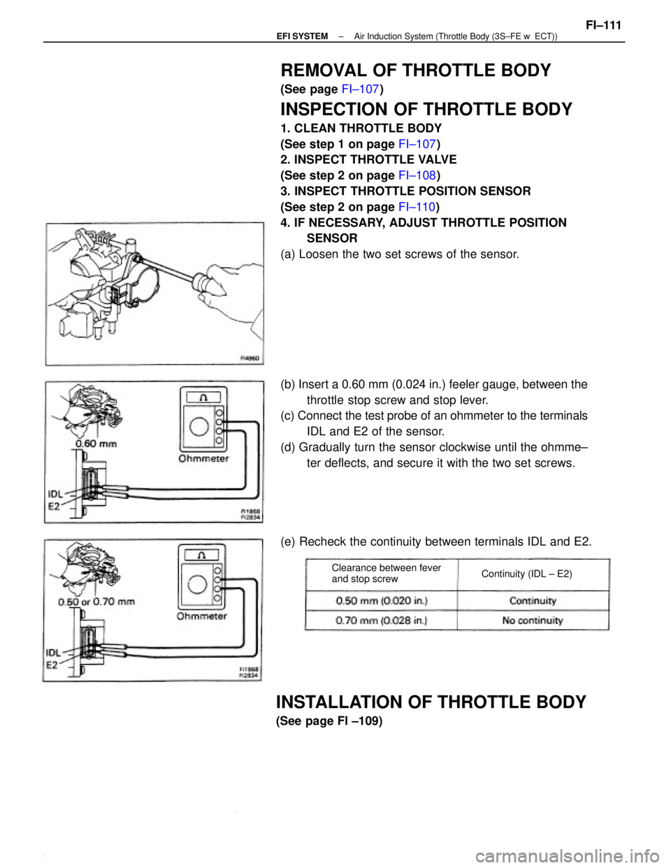
4. IF NECESSARY, ADJUST THROTTLE POSITION
SENSOR
(a) Loosen the two set screws of the sensor.
(b) Insert a 0.60 mm (0.024 in.) feeler gauge, between the
throttle stop screw and stop lever.
(c) Connect the test probe of an ohmmeter to the terminals
IDL and E2 of the sensor.
(d) Gradually turn the sensor clockwise until the ohmme±
ter deflects, and secure it with the two set screws.
INSTALLATION OF THROTTLE BODY
(See page Fl ±109)(e) Recheck the continuity between terminals IDL and E2.
Clearance between fever
and stop screwContinuity (IDL ± E2)
± EFI SYSTEMAir Induction System (Throttle Body (3S±FE w ECT))FI±111
Page 1126 of 2389
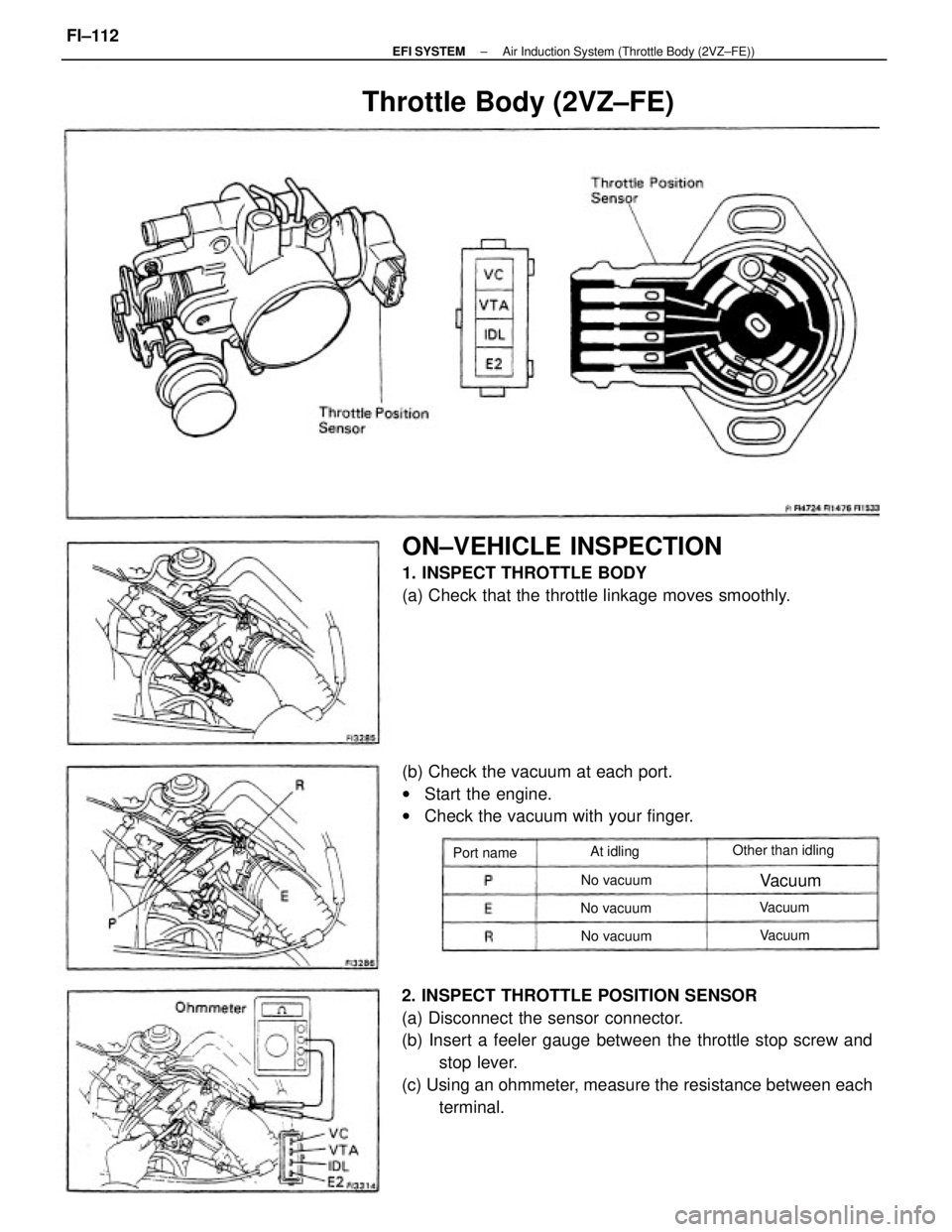
2. INSPECT THROTTLE POSITION SENSOR
(a) Disconnect the sensor connector.
(b) Insert a feeler gauge between the throttle stop screw and
stop lever.
(c) Using an ohmmeter, measure the resistance between each
terminal.
ON±VEHICLE INSPECTION
1. INSPECT THROTTLE BODY
(a) Check that the throttle linkage moves smoothly.
(b) Check the vacuum at each port.
wStart the engine.
wCheck the vacuum with your finger.
Throttle Body (2VZ±FE)
Other than idling
No vacuum No vacuum
No vacuum Port nameAt idling
Vacuum
Vacuum
Vacuum
± EFI SYSTEMAir Induction System (Throttle Body (2VZ±FE))FI±112
Page 1127 of 2389
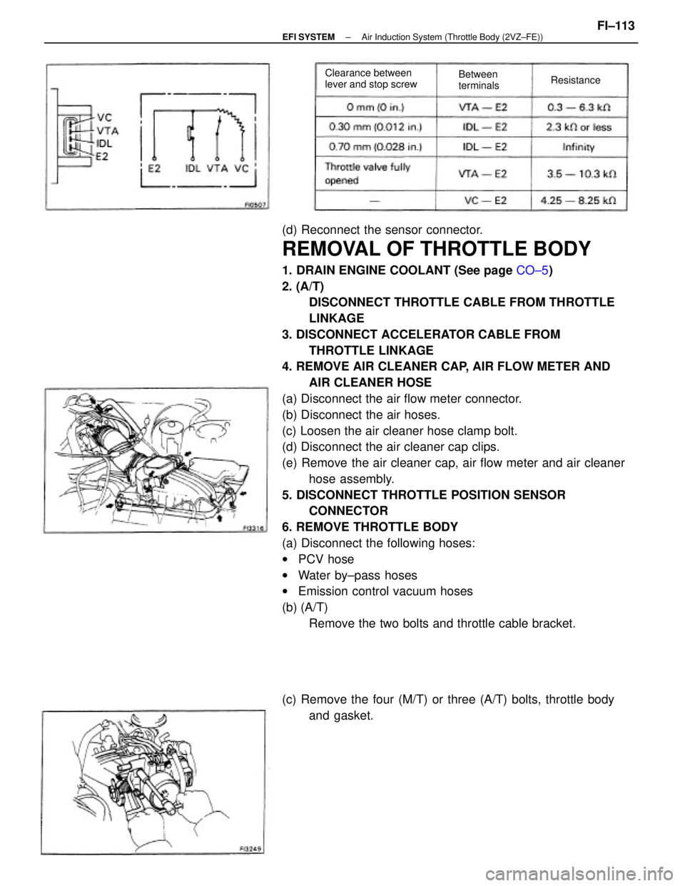
(d) Reconnect the sensor connector.
REMOVAL OF THROTTLE BODY
1. DRAIN ENGINE COOLANT (See page CO±5)
2. (A/T)
DISCONNECT THROTTLE CABLE FROM THROTTLE
LINKAGE
3. DISCONNECT ACCELERATOR CABLE FROM
THROTTLE LINKAGE
4. REMOVE AIR CLEANER CAP, AIR FLOW METER AND
AIR CLEANER HOSE
(a) Disconnect the air flow meter connector.
(b) Disconnect the air hoses.
(c) Loosen the air cleaner hose clamp bolt.
(d) Disconnect the air cleaner cap clips.
(e) Remove the air cleaner cap, air flow meter and air cleaner
hose assembly.
5. DISCONNECT THROTTLE POSITION SENSOR
CONNECTOR
6. REMOVE THROTTLE BODY
(a) Disconnect the following hoses:
wPCV hose
wWater by±pass hoses
wEmission control vacuum hoses
(b) (A/T)
Remove the two bolts and throttle cable bracket.
(c) Remove the four (M/T) or three (A/T) bolts, throttle body
and gasket.
Clearance between
lever and stop screwBetween
terminalsResistance
± EFI SYSTEMAir Induction System (Throttle Body (2VZ±FE))FI±113
Page 1128 of 2389
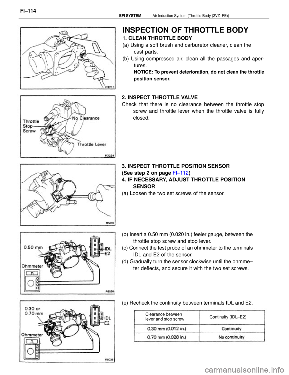
INSPECTION OF THROTTLE BODY
1. CLEAN THROTTLE BODY
(a) Using a soft brush and carburetor cleaner, clean the
cast parts.
(b) Using compressed air, clean all the passages and aper-
tures.
NOTICE: To prevent deterioration, do not clean the throttle
position sensor.
(b) Insert a 0.50 mm (0.020 in.) feeler gauge, between the
throttle stop screw and stop lever.
(c) Connect the test probe of an ohmmeter to the terminals
IDL and E2 of the sensor.
(d) Gradually turn the sensor clockwise until the ohmme±
ter deflects, and secure it with the two set screws. 3. INSPECT THROTTLE POSITION SENSOR
(See step 2 on page FI±112)
4. IF NECESSARY, ADJUST THROTTLE POSITION
SENSOR
(a) Loosen the two set screws of the sensor. 2. INSPECT THROTTLE VALVE
Check that there is no clearance between the throttle stop
screw and throttle lever when the throttle valve is fully
closed.
(e) Recheck the continuity between terminals IDL and E2.
Clearance between
lever and stop screwContinuity (IDL±E2)
± EFI SYSTEMAir Induction System (Throttle Body (2VZ±FE))FI±114