flat tire TOYOTA CAMRY V20 1986 Service Information
[x] Cancel search | Manufacturer: TOYOTA, Model Year: 1986, Model line: CAMRY V20, Model: TOYOTA CAMRY V20 1986Pages: 2389, PDF Size: 84.44 MB
Page 781 of 2389
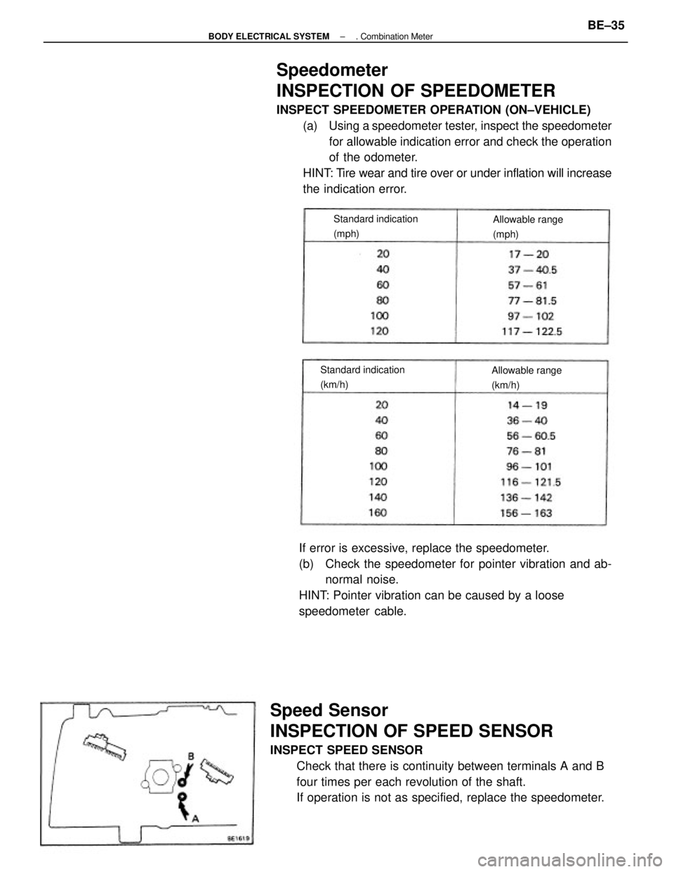
Speedometer
INSPECTION OF SPEEDOMETER
INSPECT SPEEDOMETER OPERATION (ON±VEHICLE)
(a) Using a speedometer tester, inspect the speedometer
for allowable indication error and check the operation
of the odometer.
HINT: Tire wear and tire over or under inflation will increase
the indication error.
Speed Sensor
INSPECTION OF SPEED SENSOR
INSPECT SPEED SENSOR
Check that there is continuity between terminals A and B
four times per each revolution of the shaft.
If operation is not as specified, replace the speedometer.If error is excessive, replace the speedometer.
(b) Check the speedometer for pointer vibration and ab-
normal noise.
HINT: Pointer vibration can be caused by a loose
speedometer cable.
Standard indication
(km/h)Standard indication
(mph)Allowable range
(mph)
Allowable range
(km/h)
± BODY ELECTRICAL SYSTEM. Combination MeterBE±35
Page 852 of 2389
PRECAUTIONS
1. Care must be taken to replace each part properly as it
could affect the performance of the brake system and re-
sult in a driving hazard. Replace the parts with parts of the
same part number or equivalent.
2. It is very important to keep parts and the area clean when
repairing the brake system.
Parking brake out of adjustment
Binding parking brake wire
Booster push rod out of adjustment
Tension or return spring faulty
Brake line restricted
Lining cracked or distorted
Pad cracked or distorted
Wheel cylinder or caliper piston sticking
Adjuster broken
Master cylinder faulty
Brake shoes distorted, linings worn or glazed
Brake pads distorted, worn or glazed
Drum or disc out of round
Tension or return spring faulty
Wheel cylinder faulty
Brake cylinder faulty
Piston frozen in brake cylinder
Brake pad stickingReplace brake shoes
Replace pads
Repair leak
Repair or replace master cylinder
Bleed brake system
Repair wheel cylinder
Repair cylinder
Repair brake cylinder
Repair or replace adjuster Air in brake system
Wheel cylinder faulty
Brake cylinder faulty
Piston seals worn or damaged
Rear brake automatic adjuster faulty
Adjust parking brake
Repair as necessary
Adjust push rod
Replace spring
Repair as necessary
Replace shoe
Replace pad
Repair as necessary
Replace pads
Replace drum or disc
Replace spring
Repair wheel cylinder
Repair cylinder
Repair cylinder
Replace padsInflate tires to proper pressure
Check for cause. Replace shoes
or pads
Replace brake shoes Linings worn
Brake pads worn
Leak in brake system
Master cylinder faulty
BR±18, 34
BR±18, 26
34
BR±26, 42
BR±26
BR±18, 34
BR±18, 34
BR±18, 34 Replace adjuster
Repair or replace master
cylinder
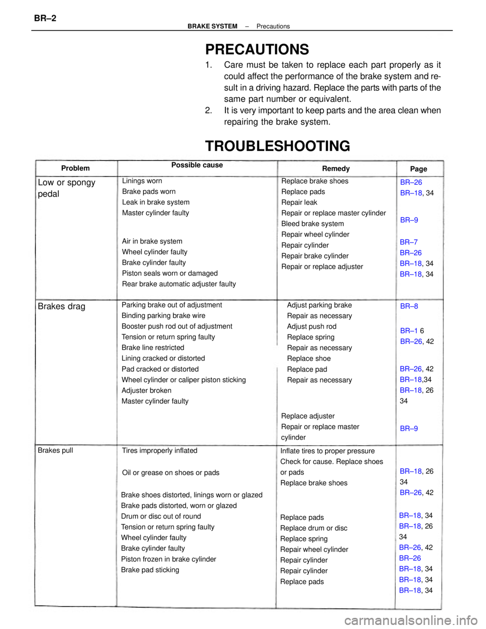
TROUBLESHOOTING
BR±7
BR±26
BR±18, 34
BR±18, 34
BR±26, 42
BR±18,34
BR±18, 26
34
Oil or grease on shoes or pads Tires improperly inflated
BR±18, 26
34
BR±26, 42
Low or spongy
pedalBR±26
BR±18, 34
BR±1 6
BR±26, 42 Possible cause
Brakes drag
Brakes pullRemedy Problem
Page
BR±8
BR±9BR±9
± BRAKE SYSTEMPrecautionsBR±2
Page 853 of 2389
PRECAUTIONS
1. Care must be taken to replace each part properly as it
could affect the performance of the brake system and re-
sult in a driving hazard. Replace the parts with parts of the
same part number or equivalent.
2. It is very important to keep parts and the area clean when
repairing the brake system.
Parking brake out of adjustment
Binding parking brake wire
Booster push rod out of adjustment
Tension or return spring faulty
Brake line restricted
Lining cracked or distorted
Pad cracked or distorted
Wheel cylinder or caliper piston sticking
Adjuster broken
Master cylinder faulty
Brake shoes distorted, linings worn or glazed
Brake pads distorted, worn or glazed
Drum or disc out of round
Tension or return spring faulty
Wheel cylinder faulty
Brake cylinder faulty
Piston frozen in brake cylinder
Brake pad stickingReplace brake shoes
Replace pads
Repair leak
Repair or replace master cylinder
Bleed brake system
Repair wheel cylinder
Repair cylinder
Repair brake cylinder
Repair or replace adjuster Air in brake system
Wheel cylinder faulty
Brake cylinder faulty
Piston seals worn or damaged
Rear brake automatic adjuster faulty
Adjust parking brake
Repair as necessary
Adjust push rod
Replace spring
Repair as necessary
Replace shoe
Replace pad
Repair as necessary
Replace pads
Replace drum or disc
Replace spring
Repair wheel cylinder
Repair cylinder
Repair cylinder
Replace padsInflate tires to proper pressure
Check for cause. Replace shoes
or pads
Replace brake shoes Linings worn
Brake pads worn
Leak in brake system
Master cylinder faulty
BR±18, 34
BR±18, 26
34
BR±26, 42
BR±26
BR±18, 34
BR±18, 34
BR±18, 34 Replace adjuster
Repair or replace master
cylinder
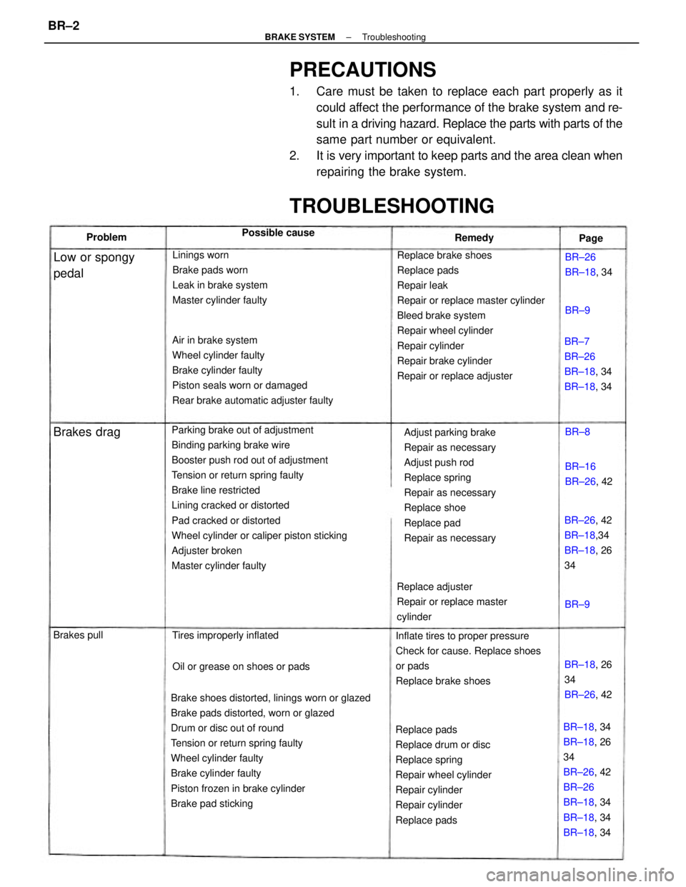
TROUBLESHOOTING
BR±7
BR±26
BR±18, 34
BR±18, 34
BR±26, 42
BR±18,34
BR±18, 26
34
Oil or grease on shoes or pads Tires improperly inflated
BR±18, 26
34
BR±26, 42
Low or spongy
pedalBR±26
BR±18, 34
BR±16
BR±26, 42 Possible cause
Brakes drag
Brakes pullRemedy Problem
Page
BR±8
BR±9BR±9
± BRAKE SYSTEMTroubleshootingBR±2
Page 1186 of 2389
Fuel leak
Air cleaner clogged
Incorrect ignition timing
EFI system problems
wInjector faulty
wDeceleration fuel cut system faulty
Idle speed too high
Spark plug faulty
EGR system always on
Low compression
Tires improperly inflated
Clutch slips
Brakes drag
Incorrect idle speed
Incorrect ignition timing
Vacuum leaks
wPCV line
wEGR line
wIntake manifold
wAir intake chamber
wThrottle body
wISC valve
wBrake booster line
EFI system problemsCheck ISC system
Inspect plugs
Check EGR system
Check compression
Inflate tires to proper pressure
Troubleshoot clutch
Troubleshoot brakesRepair as necessary
Check air cleaner
Reset timing
Repair as necessary
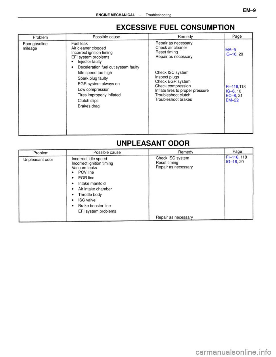
EXCESSIVE FUEL CONSUMPTION
Check ISC system
Reset timing
Repair as necessaryFI±116,118
IG±6, 10
EC±8, 21
EM±22
UNPLEASANT ODOR
Poor gasoline
mileage
FI±116, 118
IG±16, 20
Repair as necessaryMA±5
IG±16, 20
Unpleasant odorPossible cause Possible cause
Problem
ProblemRemedy
RemedyPage Page
± ENGINE MECHANICALTroubleshootingEM±9
Page 1359 of 2389
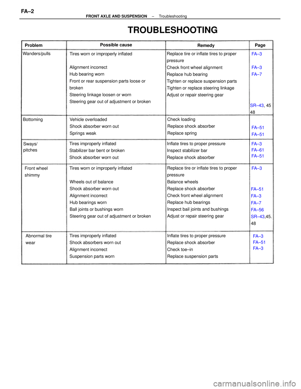
Replace tire or inflate tires to proper
pressure
Check front wheel alignment
Replace hub bearing
Tighten or replace suspension parts
Tighten or replace steering linkage
Adjust or repair steering gear
Replace tire or inflate tires to proper
pressure
Balance wheels
Replace shock absorber
Check front wheel alignment
Replace hub bearings
Inspect bail joints and bushings
Adjust or repair steering gear Wheels out of balance
Shock absorber worn out
Alignment incorrect
Hub bearings worn
Ball joints or bushings worn
Steering gear out of adjustment or broken Alignment incorrect
Hub bearing worn
Front or rear suspension parts loose or
broken
Steering linkage loosen or worn
Steering gear out of adjustment or broken
Inflate tires to proper pressure
Replace shock absorber
Check toe±in
Replace suspension parts Tires improperly inflated
Shock absorbers worn out
Alignment incorrect
Suspension parts wornInflate tires to proper pressure
Inspect stabilizer bar
Replace shock absorber Tires improperly inflated
Stabilizer bar bent or broken
Shock absorber worn outVehicle overloaded
Shock absorber worn out
Springs weakCheck loading
Replace shock absorber
Replace spring
FA±51
FA±3
FA±7
FA±56
SR±43,45.
48
TROUBLESHOOTING
Tires worn or improperly inflatedTires worn or improperly inflated
Abnormal tire
wear Front wheel
shimmyFA±3
FA±61
FA±51
FA±3
FA±51
FA±3 SR±43, 45
48 Possible cause
Sways/
pitches Wanders/pulls
FA±51
FA±51 BottomingFA±3
FA±7 Problem
RemedyPage
FA±3
FA±3
± FRONT AXLE AND SUSPENSIONTroubleshootingFA ± 2
Page 1360 of 2389
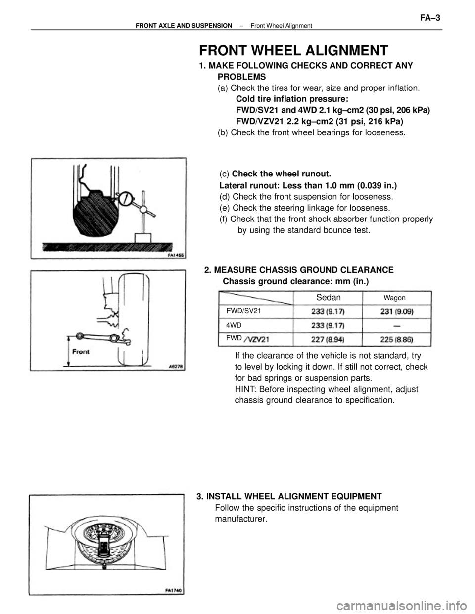
FRONT WHEEL ALIGNMENT
1. MAKE FOLLOWING CHECKS AND CORRECT ANY
PROBLEMS
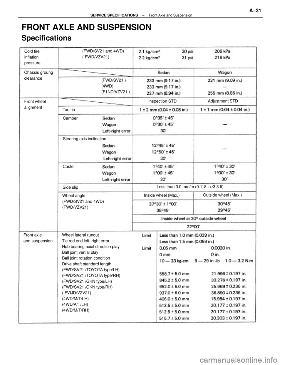
(a) Check the tires for wear, size and proper inflation.
Cold tire inflation pressure:
FWD/SV21 and 4WD 2.1 kg±cm2 (30 psi, 206 kPa)
FWD/VZV21 2.2 kg±cm2 (31 psi, 216 kPa)
(b) Check the front wheel bearings for looseness.
(c) Check the wheel runout.
Lateral runout: Less than 1.0 mm (0.039 in.)
(d) Check the front suspension for looseness.
(e) Check the steering linkage for looseness.
(f) Check that the front shock absorber function properly
by using the standard bounce test.
If the clearance of the vehicle is not standard, try
to level by locking it down. If still not correct, check
for bad springs or suspension parts.
HINT: Before inspecting wheel alignment, adjust
chassis ground clearance to specification.
3. INSTALL WHEEL ALIGNMENT EQUIPMENT
Follow the specific instructions of the equipment
manufacturer. 2. MEASURE CHASSIS GROUND CLEARANCE
Chassis ground clearance: mm (in.)
FWD/SV21Wagon
Sedan
4WD
FWD
± FRONT AXLE AND SUSPENSIONFront Wheel AlignmentFA ± 3
Page 2148 of 2389
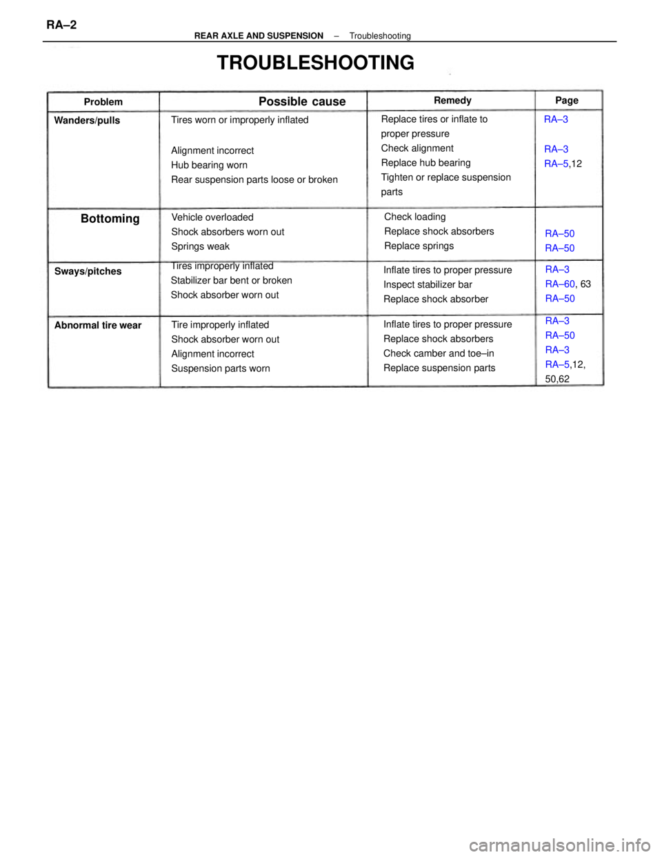
Replace tires or inflate to
proper pressure
Check alignment
Replace hub bearing
Tighten or replace suspension
parts
Inflate tires to proper pressure
Replace shock absorbers
Check camber and toe±in
Replace suspension parts Alignment incorrect
Hub bearing worn
Rear suspension parts loose or broken
Tire improperly inflated
Shock absorber worn out
Alignment incorrect
Suspension parts worn Tires improperly inflated
Stabilizer bar bent or broken
Shock absorber worn outInflate tires to proper pressure
Inspect stabilizer bar
Replace shock absorber
TROUBLESHOOTING
Vehicle overloaded
Shock absorbers worn out
Springs weakCheck loading
Replace shock absorbers
Replace springs
RA±3
RA±50
RA±3
RA±5,12,
50,62 Tires worn or improperly inflated
RA±3
RA±60, 63
RA±50
Abnormal tire wearRA±3
RA±5,12 Wanders/pulls
Sways/pitches
Possible cause
RA±50
RA±50
Bottoming
Remedy
ProblemPage
RA±3
± REAR AXLE AND SUSPENSIONTroubleshootingRA±2
Page 2149 of 2389
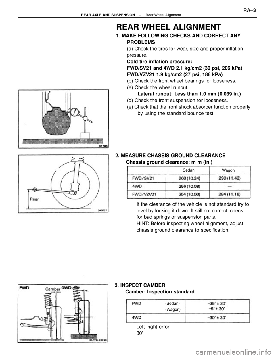
REAR WHEEL ALIGNMENT
1. MAKE FOLLOWING CHECKS AND CORRECT ANY
PROBLEMS
(a) Check the tires for wear, size and proper inflation
pressure.
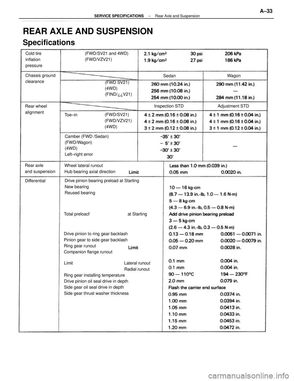
Cold tire inflation pressure:
FWD/SV21 and 4WD 2.1 kg/cm2 (30 psi, 206 kPa)
FWD/VZV21 1.9 kg/cm2 (27 psi, 186 kPa)
(b) Check the front wheel bearings for looseness.
(e) Check the wheel runout.
Lateral runout: Less than 1.0 mm (0.039 in.)
(d) Check the front suspension for looseness.
(e) Check that the front shock absorber function properly
by using the standard bounce test.
If the clearance of the vehicle is not standard try to
level by locking it down. If still not correct, check
for bad springs or suspension parts.
HINT: Before inspecting wheel alignment, adjust
chassis ground clearance to specification. 2. MEASURE CHASSIS GROUND CLEARANCE
Chassis ground clearance: m m (in.)
3. INSPECT CAMBER
Camber: Inspection standard
Left±right error
30'
(Sedan)
(Wagon)Wagon Sedan
± REAR AXLE AND SUSPENSIONRear Wheel AlignmentRA±3
Page 2269 of 2389
Wheel lateral runout
Tie rod end left±right error
Hub bearing axial direction play
Ball joint vertial play
Ball joint rotation condition
Drive shaft standard length
(FWD/SV21 /TOYOTA type/LH)
(FWD/SV21 /TOYOTA type/RH)
(FWD/SV21 /GKN type/LH)
(FWD/SV21 /GKN type/RH)
( FVIJD/VZV21)
(4WD/M/T/LH)
(4WD/A/T/LH)
(4WD/M/T/RH)
FRONT AXLE AND SUSPENSION
Specifications
Wheel angle
(FWD/SV21 and 4WD)
(FWD/VZV21)(FWD/SV21 and 4WD)
( FWD/VZV21)
Less than 3.0 mm/m (0.118 in./3.3 ft) (FWD/SV21 )
(4WD)
(F1ND/VZV21 )
Front axle
and suspensionChassis groung
clearance
Steering axis inclination Cold tire
inflation
pressure
Front wheel
alignment
Outside wheel (Max.)
Inside wheel (Max.)Adjustment STD
Inspection STD
Side slipCamber
Caster Toe±in
± SERVICE SPECIFICATIONSFront Axle and SuspensionA±31
Page 2271 of 2389
Limit Lateral runout
Radial runout
Ring gear installing temperature
Drive pinion oil seal drive in depth
Side gear oil seal drive in depth
Side gear thrust washer thicknessDrive pinion bearing preload at Starting
New bearing
Reused bearing
Drive pinion to ring gear backlash
Pinion gear to side gear backlash
Ring gear runout
Companion flange runout
REAR AXLE AND SUSPENSION
Specifications
Camber (FWD /Sedan)
(FWD/Wagon)
(4WD)
Left±right error
Wheel lateral runout
Hub bearing axial direction(FWD/SV21 and 4WD)
(FWD/VZV21)
(FWD SV21)
(4WD)
(FIND/¿¿V21)
(FWD/SV21)
(FWD/VZV21)
(4WD)
Rear axle
and suspensionChassis ground
clearanceCold tire
inflation
pressure
Rear wheel
alignmentAdjustment STD Inspection STD
Total preloacf at Starting DifferentialWagon
Toe±inSedan
± SERVICE SPECIFICATIONSRear Axle and SuspensionA±33