coolant temperature TOYOTA COROLLA CROSS 2022 Owners Manual
[x] Cancel search | Manufacturer: TOYOTA, Model Year: 2022, Model line: COROLLA CROSS, Model: TOYOTA COROLLA CROSS 2022Pages: 612, PDF Size: 17.18 MB
Page 77 of 612
772-1. Instrument cluster
2
Vehicle status information and indicators
7-inch display (when digital speedometer is displayed)
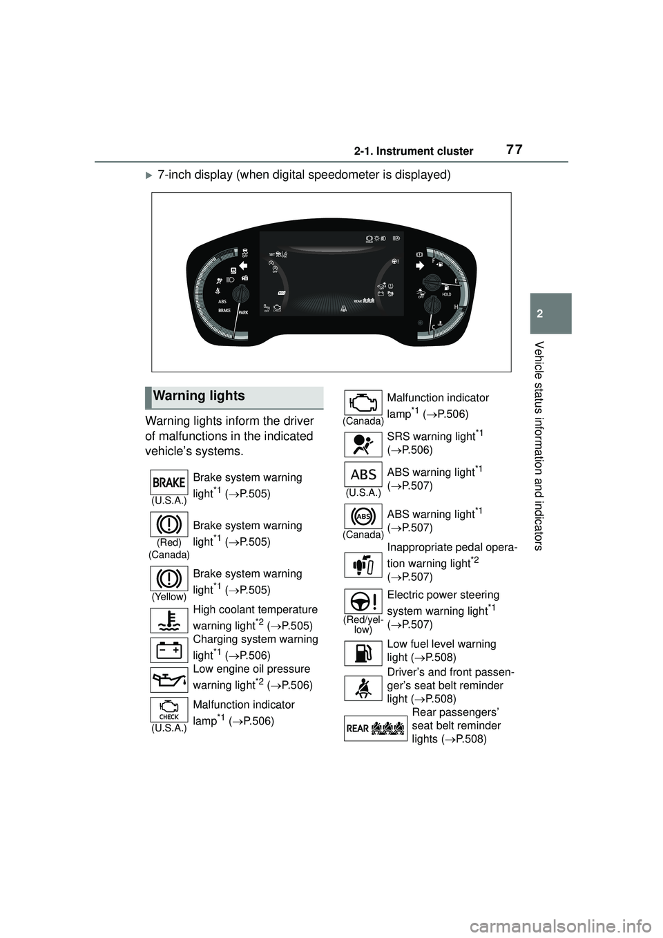
Warning lights inform the driver
of malfunctions in the indicated
vehicle’s systems.
Warning lights
(U.S.A.)
Brake system warning
light
*1 ( P.505)
(Red)
(Canada)
Brake system warning
light
*1 ( P.505)
(Yellow)
Brake system warning
light
*1 ( P.505)
High coolant temperature
warning light
*2 ( P.505)
Charging system warning
light
*1 ( P.506)
Low engine oil pressure
warning light
*2 ( P.506)
(U.S.A.)
Malfunction indicator
lamp
*1 ( P.506)
(Canada)
Malfunction indicator
lamp
*1 ( P.506)
SRS warning light
*1
( P.506)
(U.S.A.)
ABS warning light*1
( P.507)
(Canada)
ABS warning light*1
( P.507)
Inappropriate pedal opera-
tion warning light
*2
( P.507)
(Red/yel-
low)
Electric power steering
system warning light
*1
( P.507)
Low fuel level warning
light ( P.508)
Driver’s and front passen-
ger’s seat belt reminder
light ( P.508)
Rear passengers’
seat belt reminder
lights ( P.508)
Page 81 of 612
812-1. Instrument cluster
2
Vehicle status information and indicators
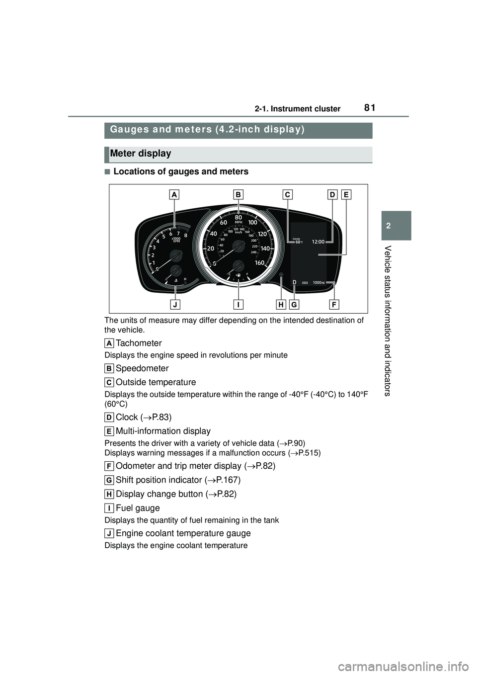
■Locations of gauges and meters
The units of measure may differ depending on the intended destination of
the vehicle.
Tachometer
Displays the engine speed in revolutions per minute
Speedometer
Outside temperature
Displays the outside temperature within the range of -40°F (-40°C) to 140°F
(60°C)
Clock (P. 8 3 )
Multi-information display
Presents the driver with a variety of vehicle data ( P.90)
Displays warning me ssages if a malfunction occurs ( P.515)
Odometer and trip meter display ( P.82)
Shift position indicator ( P.167)
Display change button ( P.82)
Fuel gauge
Displays the quantity of fuel remaining in the tank
Engine coolant temperature gauge
Displays the engine coolant temperature
Gauges and meters (4.2-inch display)
Meter display
Page 82 of 612
822-1. Instrument cluster
■Outside temperature display
●In the following situations, the cor-
rect outside temperature may not
be displayed, or the display may
take longer than normal to
change:
• When stopped, or driving at low
speeds (less than 16 mph [25
km/h])
• When the outside temperature
has changed suddenly (at the
entrance/exit of a garage, tunnel,
etc.)
●When “--” or “E” is displayed, the
system may be malfunctioning.
Take your vehicle to your Toyota
dealer.
■Liquid crystal display
P. 9 1
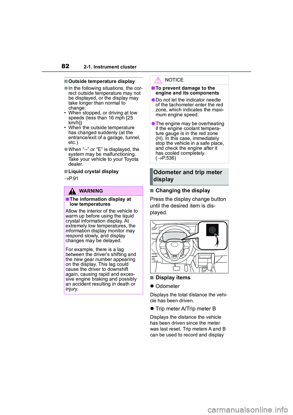
■Changing the display
Press the display change button
until the desired item is dis-
played.
■Display items
Odometer
Displays the total distance the vehi-
cle has been driven.
Trip meter A/Trip meter B
Displays the distance the vehicle
has been driven since the meter
was last reset. Trip meters A and B
can be used to record and display
WARNING
■The information display at
low temperatures
Allow the interior of the vehicle to
warm up before using the liquid
crystal information display. At
extremely low temperatures, the
information display monitor may
respond slowly, and display
changes may be delayed.
For example, there is a lag
between the driver’s shifting and
the new gear number appearing
on the display. This lag could
cause the driver to downshift
again, causing rapid and exces-
sive engine braking and possibly
an accident resulting in death or
injury.
NOTICE
■To prevent damage to the
engine and its components
●Do not let the indicator needle
of the tachometer enter the red
zone, which indicates the maxi-
mum engine speed.
●The engine may be overheating
if the engine coolant tempera-
ture gauge is in the red zone
(H). In this case, immediately
stop the vehicle in a safe place,
and check the engine after it
has cooled completely.
( P.536)
Odometer and trip meter
display
Page 85 of 612
852-1. Instrument cluster
2
Vehicle status information and indicators
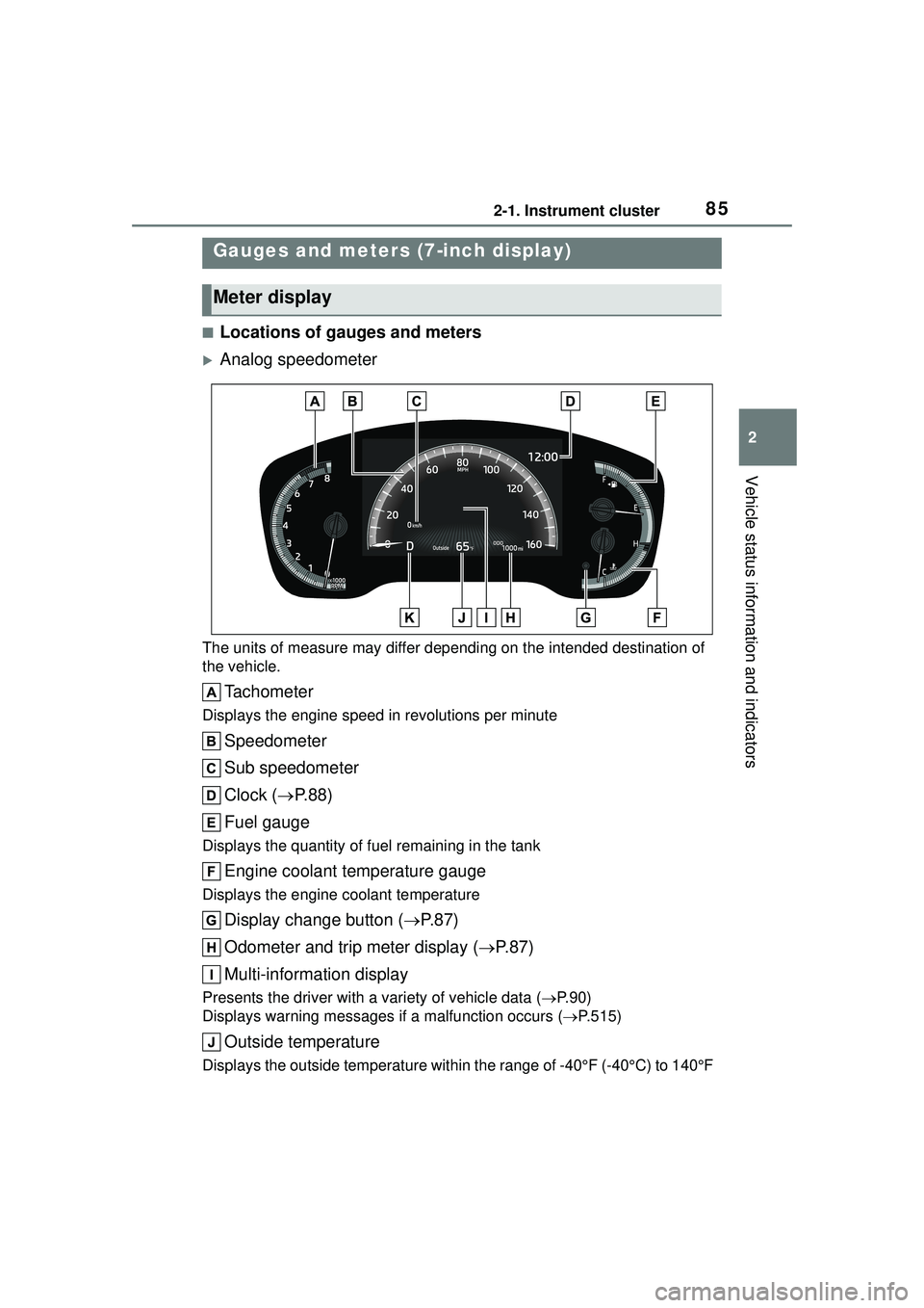
■Locations of gauges and meters
Analog speedometer
The units of measure may differ depending on the intended destination of
the vehicle.
Tachometer
Displays the engine speed in revolutions per minute
Speedometer
Sub speedometer
Clock (P. 8 8 )
Fuel gauge
Displays the quantity of fuel remaining in the tank
Engine coolant temperature gauge
Displays the engine coolant temperature
Display change button ( P.87)
Odometer and trip meter display ( P.87)
Multi-information display
Presents the driver with a variety of vehicle data ( P.90)
Displays warning me ssages if a malfunction occurs ( P.515)
Outside temperature
Displays the outside temperature within the range of -40°F (-40°C) to 140°F
Gauges and meters (7-inch display)
Meter display
Page 86 of 612
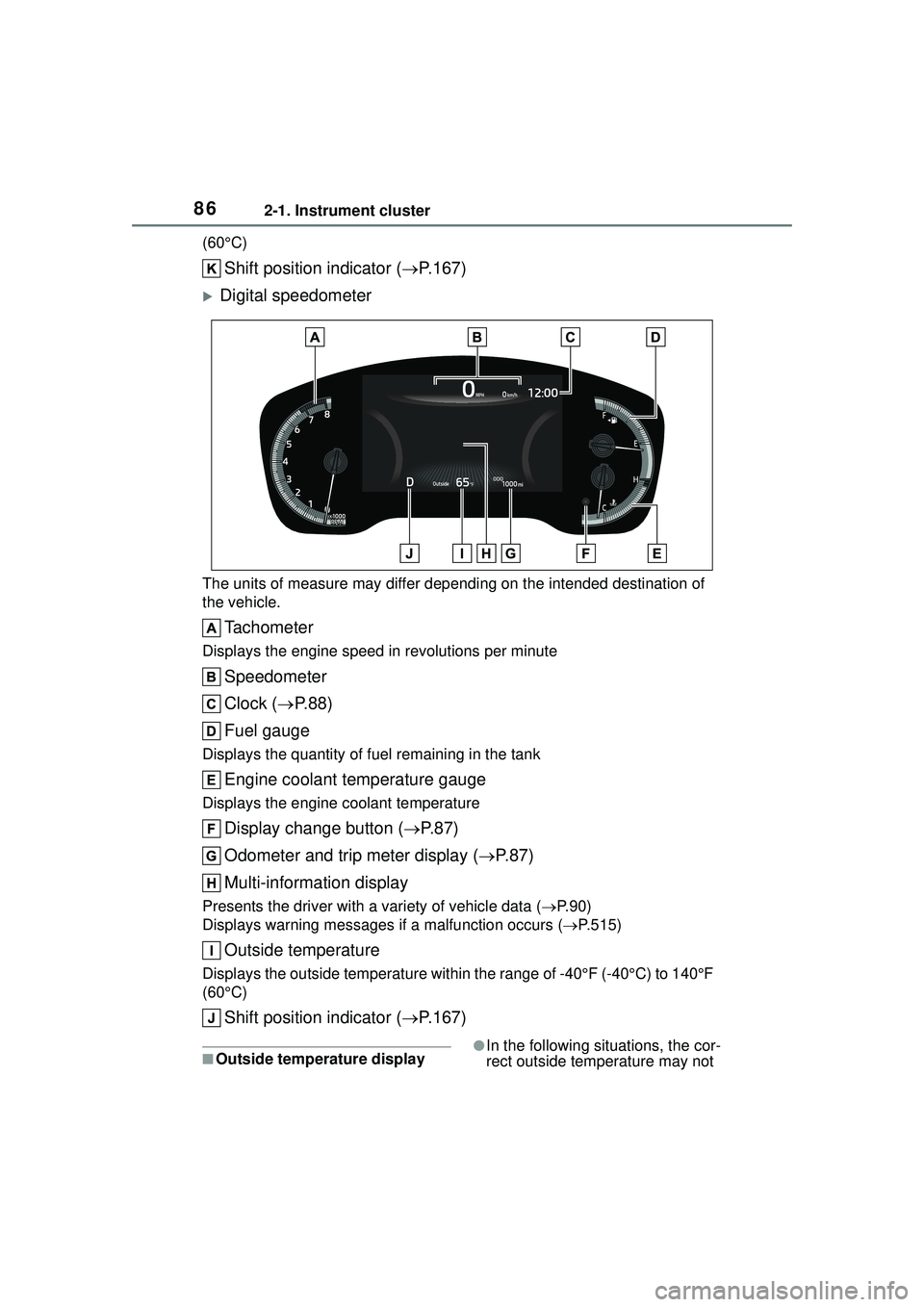
862-1. Instrument cluster
(60°C)
Shift position indicator (P.167)
Digital speedometer
The units of measure may differ depending on the intended destination of
the vehicle.
Tachometer
Displays the engine speed in revolutions per minute
Speedometer
Clock ( P. 8 8 )
Fuel gauge
Displays the quantity of fuel remaining in the tank
Engine coolant temperature gauge
Displays the engine coolant temperature
Display change button ( P.87)
Odometer and trip meter display ( P.87)
Multi-information display
Presents the driver with a variety of vehicle data ( P.90)
Displays warning me ssages if a malfunction occurs ( P.515)
Outside temperature
Displays the outside temperature within the range of -40°F (-40°C) to 140°F
(60°C)
Shift position indicator ( P.167)
■Outside temperature display●In the following situations, the cor-
rect outside temperature may not
Page 87 of 612
872-1. Instrument cluster
2
Vehicle status information and indicators
be displayed, or the display may
take longer than normal to
change:
• When stopped, or driving at low speeds (less than 16 mph [25
km/h])
• When the outside temperature has changed suddenly (at the
entrance/exit of a garage, tunnel,
etc.)
●When “--” or “E” is displayed, the
system may be malfunctioning.
Take your vehicle to your Toyota
dealer.
■Liquid crystal display
P. 9 1
■Customization
The gauges and meters can be cus-
tomized in of the multi-informa-
tion display. ( P. 9 4 )
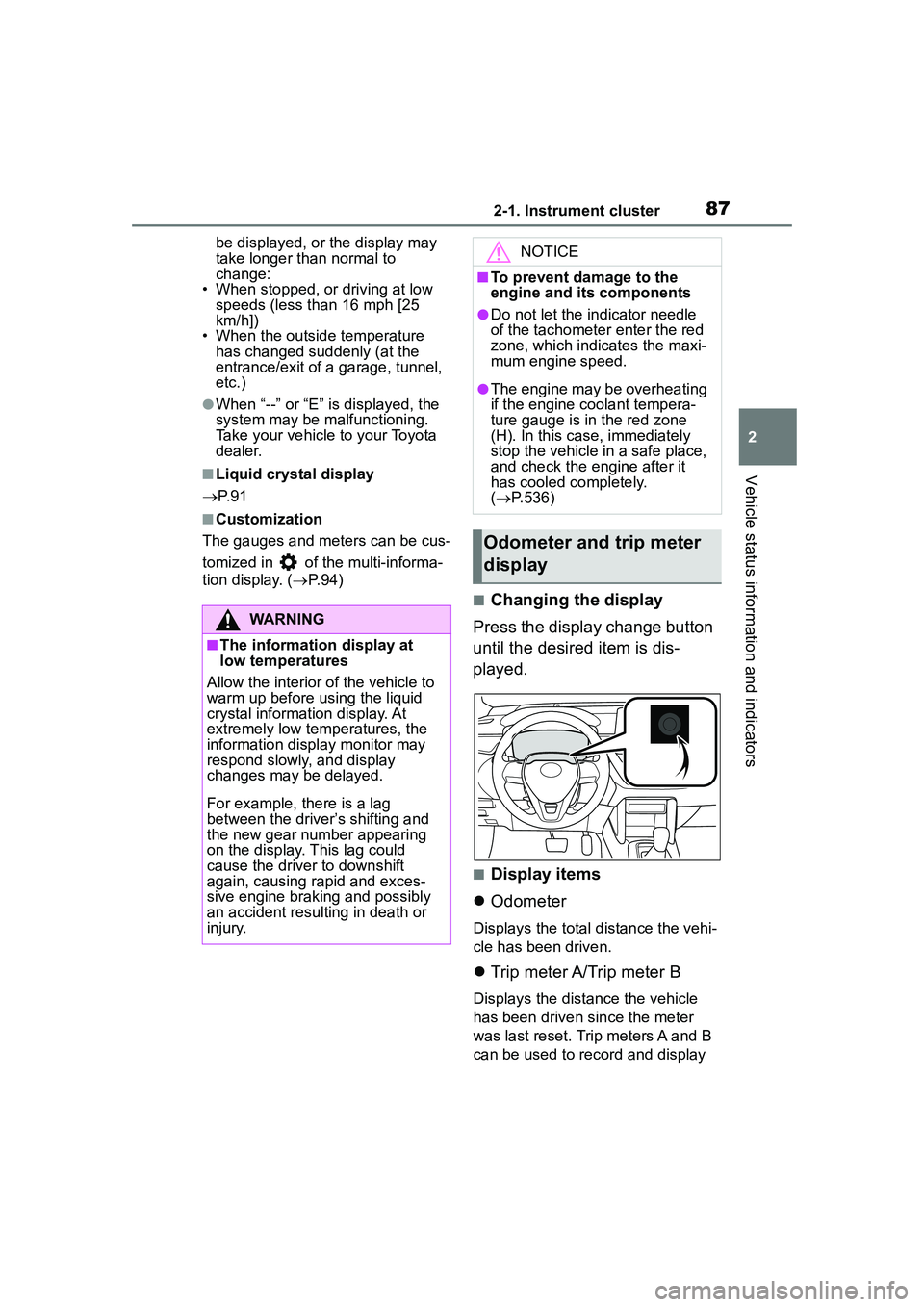
■Changing the display
Press the display change button
until the desired item is dis-
played.
■Display items
Odometer
Displays the total distance the vehi-
cle has been driven.
Trip meter A/Trip meter B
Displays the distance the vehicle
has been driven since the meter
was last reset. Trip meters A and B
can be used to record and display
WARNING
■The information display at
low temperatures
Allow the interior of the vehicle to
warm up before using the liquid
crystal information display. At
extremely low temperatures, the
information display monitor may
respond slowly, and display
changes may be delayed.
For example, there is a lag
between the driver’s shifting and
the new gear number appearing
on the display. This lag could
cause the driver to downshift
again, causing rapid and exces-
sive engine braking and possibly
an accident resulting in death or
injury.
NOTICE
■To prevent damage to the
engine and its components
●Do not let the indicator needle
of the tachometer enter the red
zone, which indicates the maxi-
mum engine speed.
●The engine may be overheating
if the engine coolant tempera-
ture gauge is in the red zone
(H). In this case, immediately
stop the vehicle in a safe place,
and check the engine after it
has cooled completely.
( P.536)
Odometer and trip meter
display
Page 159 of 612
1594-1. Before driving
4
Driving
right. (This is generally oppo-
site to reversing without a
trailer attached.) Avoid sharp
or prolonged turning. Have
someone guide you when
reversing to reduce the risk of
an accident.
As stopping distance is
increased when towing a
trailer, vehicle-to vehicle dis-
tance should be increased.
For each 10 mph (16 km/h) of
speed, allow at least one
vehicle and trailer length.
Avoid sudden braking as you
may skid, resulting in the
trailer jackknifing and a loss of
vehicle control. This is espe-
cially true on wet or slippery
surfaces.
Avoid jerky starts or sudden
acceleration.
Avoid jerky steering and
sharp turns, and slow down
before making turn.
Note that when making a turn,
the trailer wheels will be
closer than the vehicle wheels
to the inside of the turn. Com-
pensate by making a wider
than normal turning radius.
Slow down before making a
turn, in cross winds, on wet or
slippery surfaces, etc.
Increasing vehicle speed can
destabilize the trailer.
Take care when passing other
vehicles. Passing requires considerable distance. After
passing a vehicle, do not for-
get the length of your trailer,
and be sure you have plenty
of room before changing
lanes.
To maintain engine braking
efficiency and charging sys-
tem performance when using
engine braking, do not put the
transmission in D. If in the M
mode, the transmission shift
range position must be in 6 or
lower. ( P.167)
Instability happens more fre-
quently when descending
steep or long downhill grades.
Before descending, slow
down and downshift. Do not
make sudden downshifts
while descending steep or
long downhill grades.
Avoid holding the brake pedal
down too long or applying the
brakes too frequently. This
could cause the brakes to
overheat and result in
reduced braking efficiency.
Due to the added load of the
trailer, your vehicle’s engine
may overheat on hot days (at
temperatures over 85°F
[30°C]) when driving up a long
or steep grade. If the engine
coolant temperature gauge
indicates overheating, imme-
diately turn off the air condi-
tioning (if in use), pull your
vehicle off the road and stop
Page 229 of 612
2294-5. Using the driving support systems
4
Driving
■Operating conditions
●The Stop & Start system is opera-
tional when all of the following
conditions are met:
• The vehicle has been driven a cer-
tain amount of time.
• The brake pedal is being depressed firmly. (Except when
the vehicle is stopped by the
dynamic radar cruise control with
full-speed range when in vehi-
cle-to-vehicle distance control
mode)
• The D or P shift position is
selected.
• The driver’s seat belt is fastened.
• The driver’s door is closed.
• The windshield defogger is off. (vehicles without a manual air
conditioning system)
• The accelerator pedal is not being depressed.
• The engine is adequately warmed
up.
• The outside temperature is 23°F (-5°C ) or higher.
• The hood is closed. ( P.230)
●In the following situations the
engine may not be stopped by the
Stop & Start system. This is not a
malfunction of the Stop & Start
system.
• When the air conditioning system is being used.
• When the battery is undergoing a periodic recharge.
• When the battery is not sufficiently
charged, such as if the vehicle
has been parked for a long time
and the battery charge has
decreased, the electric load is
large, the battery fluid tempera-
ture is excessively low or the bat-
tery has deteriorated.
• When the brake booster vacuum is low.
• When the elapsed time since the
engine was restarted is short.
• When the vehicle is stopped fre- quently, such as when in a traffic
jam.
• When the engine coolant tem- perature or transmission fluid tem- perature is extremely low or high.
• When the vehicle is stopped on a steep incline.
• When the vehicle is being driven in a high altitude area.
• When the battery fluid tempera-
ture is extremely low or high.
• For a while after the battery termi- nals have been disconnected and
reconnected.
●When the engine is stopped by
the Stop & Start system, the
engine will be restarted automati-
cally if any of the following condi-
tions are met: (To enable the
engine to be stopped by the Stop
& Start system again, drive the
vehicle.)
• The air conditioning system is turned on. (vehicles without a
manual air conditioning system)
• The windshield defogger is turned on. (vehicles without a manual air
conditioning system)
• The shift lever is shifted from D or P.
• The shift lever is shifted from P. (When the engine is stopped by
the Stop & Start system when the
shift lever is in P.)
• The driver’s seat belt is unfas- tened.
• The driver’s door is opened.
• The Stop & Start cancel switch is
pressed.
• The accelerator pedal is depressed.
• The vehicle starts to roll on an
incline.
●When the engine is stopped by
the Stop & Start system, the
engine may restart automatically
in the following situations: (To
enable the engine to be stopped
by the Stop & Start system again,
drive the vehicle.)
• When the brake pedal is pumped
or strongly depressed.
• When the air conditioning system is being used.
• When a switch of the air condition- ing system is operated (windshield
defogger switch, etc.).
Page 458 of 612

4587-3. Do-it-yourself maintenance
Radiator
and con-
denser
( P.464)
Tire infla-
tion pres-
sure
( P.478)• Tire pressure gauge
• Compressed air
source
Washer
fluid
( P.467)
• Water or washer
fluid containing anti-
freeze (for winter
use)
• Funnel (used only for adding water or
washer fluid)
WARNING
The engine compartment contains
many mechanisms and fluids that
may move suddenly, become hot,
or become electrically energized.
To avoid death or serious injury,
observe the following precautions.
■When working on the engine
compartment
●Keep hands, clothing and tools
away from the moving fan and
engine drive belt.
●Be careful not to touch the
engine, radiator, exhaust mani-
fold, etc. right after driving as
they may be hot. Oil and other
fluids may also be hot.
●Do not leave anything that may
burn easily, such as paper and
rags, in the engine compart-
ment.
●Do not smoke, cause sparks or
expose an open flame to fuel or
the battery. Fuel and battery
fumes are flammable.
ItemsParts and tools●Be extremely cautious when
working on the battery. It con-
tains poisonous and corrosive
sulfuric acid.
■When working near the elec-
tric cooling fan or radiator
grille
Be sure the engine switch is OFF.
With the engine switch in ON, the
electric cooling fan may automati-
cally start to run if the air condi-
tioning is on and/or the coolant
temperature is high. ( P.464)
■Safety glasses
Wear safety glasses to prevent
flying or falling material, fluid
spray, etc. from getting in your
eyes.
NOTICE
■If you remove the air cleaner
filter
Driving with the air cleaner filter
removed may cause excessive
engine wear due to dirt in the air.
Page 461 of 612
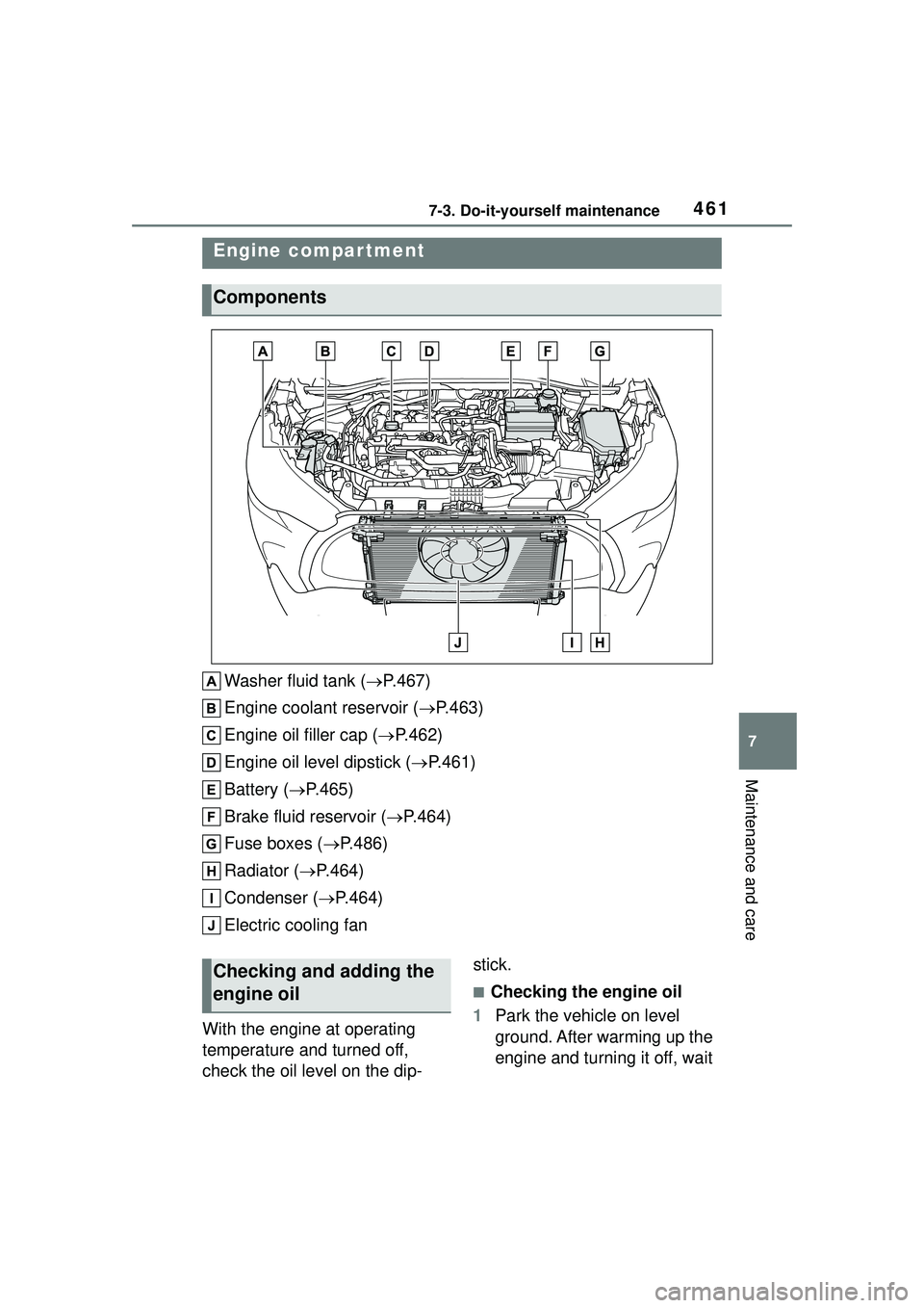
4617-3. Do-it-yourself maintenance
7
Maintenance and care
Washer fluid tank (P.467)
Engine coolant reservoir ( P.463)
Engine oil filler cap ( P.462)
Engine oil level dipstick ( P.461)
Battery ( P.465)
Brake fluid reservoir ( P.464)
Fuse boxes ( P.486)
Radiator ( P.464)
Condenser ( P.464)
Electric cooling fan
With the engine at operating
temperature and turned off,
check the oil level on the dip- stick.
■Checking the engine oil
1 Park the vehicle on level
ground. After warming up the
engine and turning it off, wait
Engine compar tment
Components
Checking and adding the
engine oil