width TOYOTA COROLLA CROSS 2022 Owners Manual
[x] Cancel search | Manufacturer: TOYOTA, Model Year: 2022, Model line: COROLLA CROSS, Model: TOYOTA COROLLA CROSS 2022Pages: 612, PDF Size: 17.18 MB
Page 149 of 612
1494-1. Before driving
4
Driving
WARNING
●Receptacles containing gaso-
line
●Aerosol cans
■Storage precautions
Observe the following precau-
tions.
Failure to do so may prevent the
pedals from being depressed
properly, may block the driver’s
vision, or may result in items hit-
ting the driver or passengers, pos-
sibly causing an accident.
●Stow cargo and luggage in the
luggage compartment when-
ever possible.
●Do not stack cargo and luggage
in the luggage compartment
higher than the seatbacks.
●When you fold down the rear
seats, long items should not be
placed directly behind the front
seats.
●Never allow anyone to ride in
the luggage compartment. It is
not designed for passengers.
They should ride in their seats
with their seat belts properly
fastened.
●Do not place cargo or luggage
in or on the following locations.
• At the feet of the driver
• On the front passenger or rear seats (when stacking items)
• On the luggage cover
• On the instrument panel
• On the dashboard
●Secure all items in the occupant
compartment.
■Capacity and distribution
●Do not exceed the maximum
axle weight rati ng or the total
vehicle weight rating.
●Even if the total load of occu-
pant’s weight and the cargo
load is less than the total load
capacity, do not apply the load
unevenly. Improper loading may
cause deterioration of steering
or braking control which may
cause death or serious injury.
■When using a roof luggage
carrier (vehicles with roof
rails)
Observe the following precau-
tions:
●Place the cargo so that its
weight is distributed evenly
between the front and rear
axles.
●If loading long or wide cargo,
never exceed the vehicle overall
length or width. (
P.542)
●Before driving, make sure the
cargo is securely fastened on
the roof luggage carrier.
●Loading cargo on the roof lug-
gage carrier will make the cen-
ter of gravity of the vehicle
higher. Avoid high speeds, sud-
den starts, sharp turns, sudden
braking or abrupt maneuvers,
otherwise it may result in loss of
control or vehicle rollover due to
failure to operate this vehicle
correctly and result in death or
serious injury.
●If driving for a long distance, on
rough roads, or at high speeds,
stop the vehicle now and then
during the trip to make sure the
cargo remains in its place.
●Do not exceed 165 lb. (75 kg)
cargo weight on the roof lug-
gage carrier.
Page 210 of 612
2104-5. Using the driving support systems
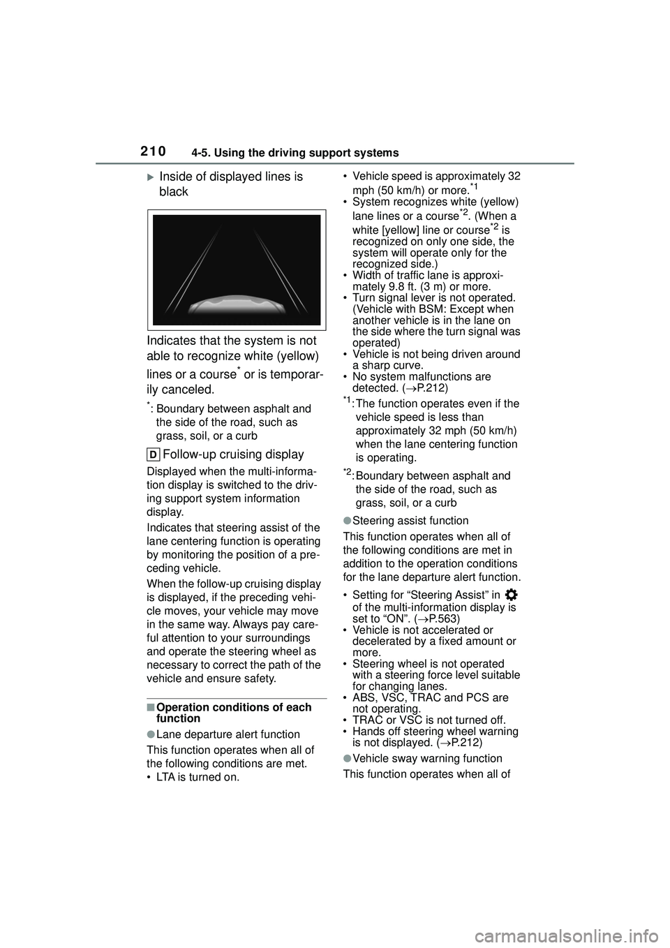
Inside of displayed lines is
black
Indicates that the system is not
able to recognize white (yellow)
lines or a course
* or is temporar-
ily canceled.
*: Boundary between asphalt and the side of the road, such as
grass, soil, or a curb
Follow-up cruising display
Displayed when the multi-informa-
tion display is switched to the driv-
ing support system information
display.
Indicates that steering assist of the
lane centering function is operating
by monitoring the position of a pre-
ceding vehicle.
When the follow-up cruising display
is displayed, if the preceding vehi-
cle moves, your vehicle may move
in the same way. Always pay care-
ful attention to your surroundings
and operate the steering wheel as
necessary to correct the path of the
vehicle and ensure safety.
■Operation conditions of each
function
●Lane departure alert function
This function operates when all of
the following conditions are met.
• LTA is turned on. • Vehicle speed is approximately 32
mph (50 km/h) or more.
*1
• System recognizes white (yellow) lane lines or a course*2. (When a
white [yellow] line or course*2 is
recognized on only one side, the
system will operate only for the
recognized side.)
• Width of traffic lane is approxi- mately 9.8 ft. (3 m) or more.
• Turn signal lever is not operated. (Vehicle with BSM: Except when
another vehicle is in the lane on
the side where the turn signal was
operated)
• Vehicle is not being driven around
a sharp curve.
• No system malfunctions are detected. ( P.212)
*1: The function operates even if the
vehicle speed is less than
approximately 32 mph (50 km/h)
when the lane centering function
is operating.
*2: Boundary between asphalt and the side of the road, such as
grass, soil, or a curb
●Steering assist function
This function operates when all of
the following conditions are met in
addition to the operation conditions
for the lane departure alert function.
• Setting for “Steering Assist” in of the multi-information display is
set to “ON”. ( P.563)
• Vehicle is not accelerated or decelerated by a fixed amount or
more.
• Steering wheel is not operated with a steering force level suitable
for changing lanes.
• ABS, VSC, TRAC and PCS are not operating.
• TRAC or VSC is not turned off.
• Hands off steering wheel warning
is not displayed. ( P.212)
●Vehicle sway warning function
This function operates when all of
Page 211 of 612
2114-5. Using the driving support systems
4
Driving
the following conditions are met.
• Setting for “Sway Warning” in of the multi-information display is
set to “ON”. ( P.563)
• Vehicle speed is approximately 32
mph (50 km/h) or more.
• Width of traffic lane is approxi- mately 9.8 ft. (3 m) or more.
• No system malfunctions are detected. ( P.212)
●Lane centering function
This function operates when all of
the following conditions are met.
• LTA is turned on.
• Setting for “Steering Assist” and “Lane Center” in of the
multi-information di splay are set to
“ON”. ( P.563)
• This function recognizes white (yellow) lane lines or the position
of a preceding vehicle (except
when the preceding vehicle is
small, such as a motorcycle).
• The dynamic radar cruise control
with full-speed range is operating
in vehicle-to-vehicle distance con-
trol mode.
• Width of traffic lane is approxi- mately 10 to 13 ft. (3 to 4 m).
• Turn signal lever is not operated.
• Vehicle is not being driven around
a sharp curve.
• No system malfunctions are
detected. ( P.212)
• Vehicle does not accelerate or decelerate by a fixed amount or
more.
• Steering wheel is not operated with a steering force level suitable
for changing lanes.
• ABS, VSC, TRAC and PCS are not operating.
• TRAC or VSC is not turned off.
• Hands off steering wheel warning
is not displayed. ( P.212)
• The vehicle is being driven in the
center of a lane.
• Steering assist function is not operating.
■Temporary cancelation of func-
tions
●When operation conditions are no
longer met, a function may be
temporarily canceled. However,
when the operation conditions are
met again, operation of the func-
tion is automatically restored.
( P.210)
●If the operation conditions
( P.208) are no longer met while
the lane centering function is
operating, the buzzer may sound
to indicate that the function has
been temporarily canceled.
■Steering assist function/lane
centering function
●Depending on the vehicle speed,
lane departure situation, road con-
ditions, etc., the driver may not
feel the function is operating or
the function may not operate at
all.
●The steering control of the func-
tion is overridden by the driver’s
steering wheel operation.
●Do not attempt to test the opera-
tion of the steering assist function.
■Lane departure alert function
●The warning buzzer may be diffi-
cult to hear due to external noise,
audio playback, etc.
●If the edge of the course* is not
clear or straight, the lane depar-
ture alert function may not oper-
ate.
●Vehicle with BSM: It may not be
possible for the system to deter-
mine if there is a danger of a colli-
sion with a vehicle in an adjacent
lane.
●Do not attempt to test the opera-
tion of the lane departure alert
function.
*: Boundary between asphalt and
the side of the road, such as
grass, soil, or a curb
Page 244 of 612
2444-5. Using the driving support systems
The rear view monitor system will be deactivated when the
shift lever is shifted to any posi-
tion other than R.
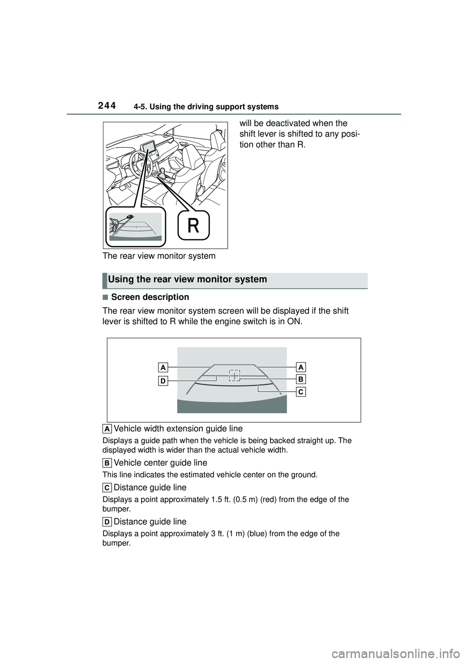
■Screen description
The rear view monitor system screen will be displayed if the shift
lever is shifted to R while the engine switch is in ON.
Vehicle width extension guide line
Displays a guide path when the vehicle is being backed straight up. The
displayed width is wider than the actual vehicle width.
Vehicle center guide line
This line indicates the estimated vehicle center on the ground.
Distance guide line
Displays a point approximately 1.5 ft. (0.5 m) (red) from the edge of the
bumper.
Distance guide line
Displays a point approximately 3 ft. (1 m) (blue) from the edge of the
bumper.
Using the rear view monitor system
Page 245 of 612
2454-5. Using the driving support systems
4
Driving
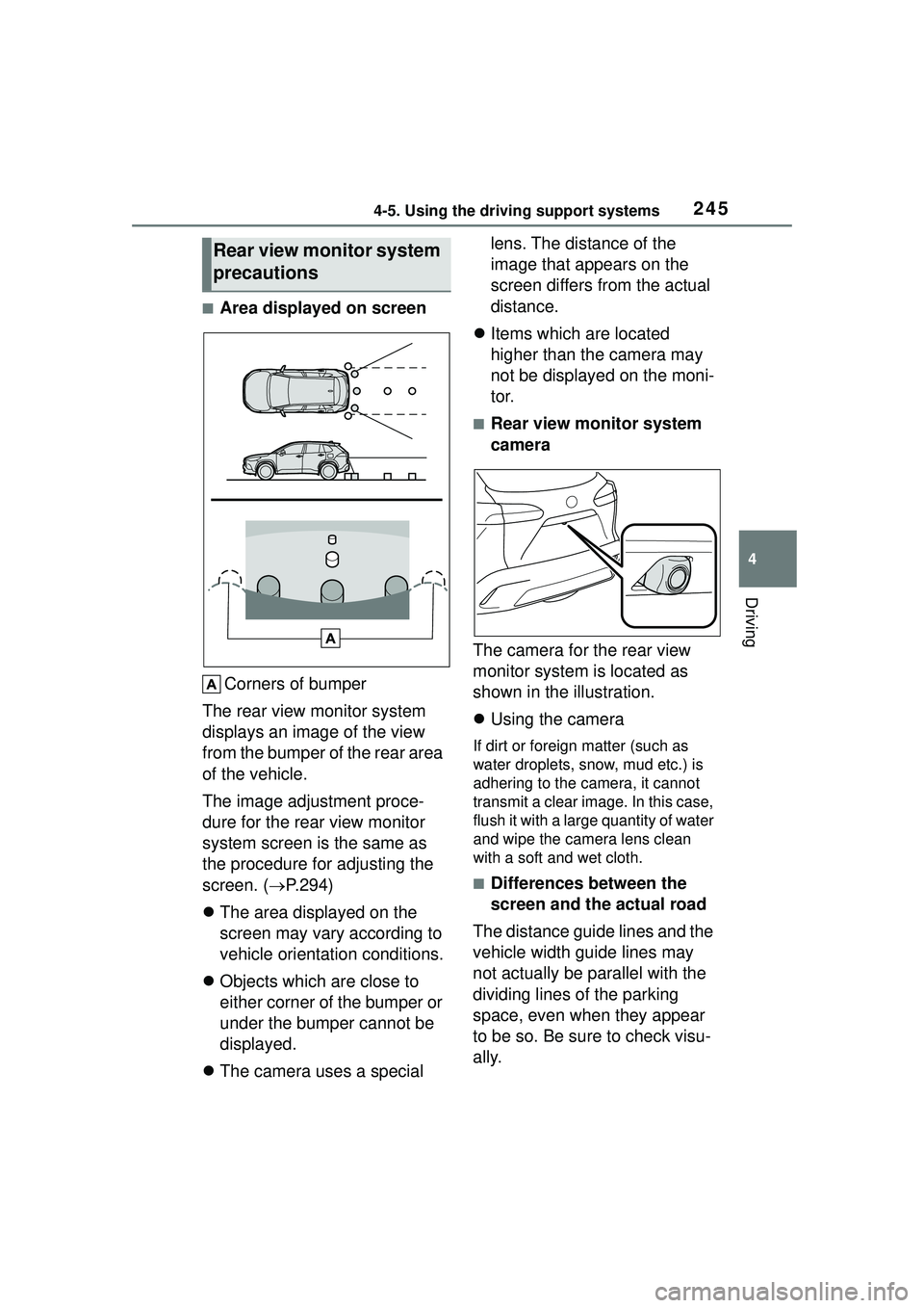
■Area displayed on screenCorners of bumper
The rear view monitor system
displays an image of the view
from the bumper of the rear area
of the vehicle.
The image adjustment proce-
dure for the rear view monitor
system screen is the same as
the procedure for adjusting the
screen. ( P.294)
The area displayed on the
screen may vary according to
vehicle orientation conditions.
Objects which are close to
either corner of the bumper or
under the bumper cannot be
displayed.
The camera uses a special lens. The distance of the
image that appears on the
screen differs from the actual
distance.
Items which are located
higher than the camera may
not be displayed on the moni-
tor.
■Rear view monitor system
camera
The camera for the rear view
monitor system is located as
shown in the illustration.
Using the camera
If dirt or foreign matter (such as
water droplets, snow, mud etc.) is
adhering to the camera, it cannot
transmit a clear image. In this case,
flush it with a large quantity of water
and wipe the camera lens clean
with a soft and wet cloth.
■Differences between the
screen and the actual road
The distance guide lines and the
vehicle width guide lines may
not actually be parallel with the
dividing lines of the parking
space, even when they appear
to be so. Be sure to check visu-
ally.
Rear view monitor system
precautions
Page 246 of 612
2464-5. Using the driving support systems
The distances between the vehi-
cle width guide lines and the left
and right dividing lines of the
parking space may not be equal,
even when they appear to be
so. Be sure to check visually.
The distance guide lines give a
distance guide for flat road sur-
faces. In any of the following sit-
uations, there is a margin of
error between the fixed guide
lines on the screen and the
actual distance/course on the
road.
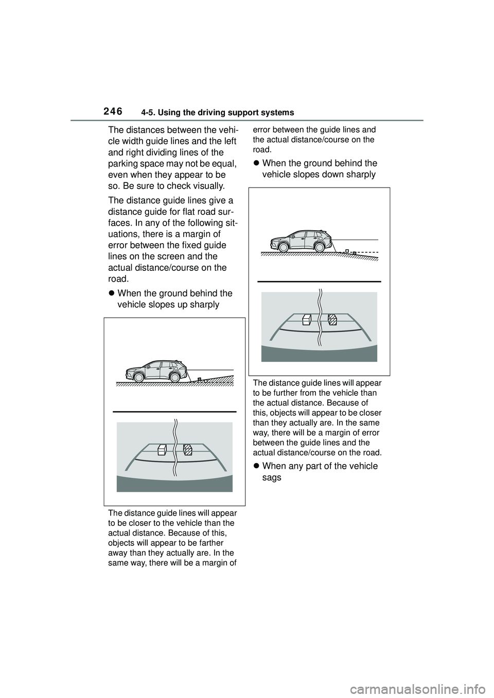
When the ground behind the
vehicle slopes up sharply
The distance guide lines will appear
to be closer to the vehicle than the
actual distance. Because of this,
objects will appear to be farther
away than they actually are. In the
same way, there will be a margin of error between the guide lines and
the actual distance/course on the
road.
When the ground behind the
vehicle slopes down sharply
The distance gui de lines will appear
to be further from the vehicle than
the actual distance. Because of
this, objects will appear to be closer
than they actually are. In the same
way, there will be a margin of error
between the guide lines and the
actual distance/course on the road.
When any part of the vehicle
sags
Page 247 of 612
2474-5. Using the driving support systems
4
Driving
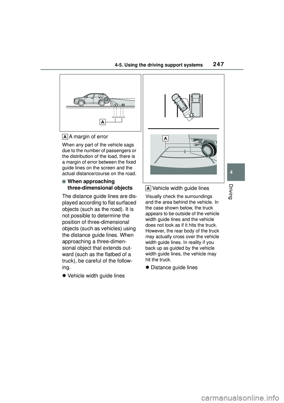
A margin of error
When any part of the vehicle sags
due to the number of passengers or
the distribution of the load, there is
a margin of error between the fixed
guide lines on the screen and the
actual distance/course on the road.
■When approaching
three-dimensional objects
The distance guide lines are dis-
played according to flat surfaced
objects (such as the road). It is
not possible to determine the
position of three-dimensional
objects (such as vehicles) using
the distance guide lines. When
approaching a three-dimen-
sional object that extends out-
ward (such as the flatbed of a
truck), be careful of the follow-
ing.
Vehicle width guide lines Vehicle width guide lines
Visually check the surroundings
and the area behind the vehicle. In
the case shown below, the truck
appears to be outside of the vehicle
width guide lines and the vehicle
does not look as if it hits the truck.
However, the rear body of the truck
may actually cross over the vehicle
width guide lines. In reality if you
back up as guided by the vehicle
width guide lines, the vehicle may
hit the truck.
Distance guide lines
Page 480 of 612
4807-3. Do-it-yourself maintenance
When replacing wheels, care
should be taken to ensure that
they are equivalent to those
removed in load capacity, diam-
eter, rim width and inset
*.
Replacement wheels are avail-
able at your Toyota dealer.
*: Conventionally refe rred to as off-
set.
Toyota does not recommend
using the following:
Wheels of different sizes or
types
Used wheels
Bent wheels that have been
straightened
■When replacing wheels
The wheels of your vehicle are
equipped with tire pressure warning
valves and transmitters that allow
the tire pressure warning system to
provide advance warning in the
event of a loss in tire inflation pres-
sure. Whenever wheels are
replaced, the tire pressure warning
valves and transmitters must be
installed. ( P.472)
WARNING
●Greater possibility of tire dam-
age while driving (due to road
hazards, expansion joints,
sharp edges in the road, etc.)
NOTICE
■When inspecting and adjust-
ing tire inflation pressure
Be sure to put the tire valve caps
back on.
If a valve cap is not installed, dirt
or moisture may get into the valve
and cause an air leak, resulting in
decreased tire inflation pressure.
Wheels
If a wheel is bent, cracked or
heavily corroded, it should
be replaced. Otherwise, the
tire may separate from the
wheel or cause a loss of
handling control.
Wheel selection
Page 542 of 612
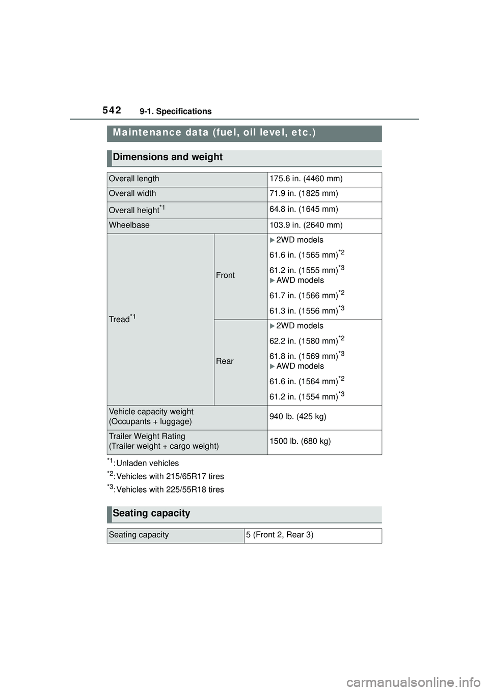
5429-1. Specifications
9-1.Specifications
*1: Unladen vehicles
*2: Vehicles with 215/65R17 tires
*3: Vehicles with 225/55R18 tires
Maintenance data (fuel, oil level, etc.)
Dimensions and weight
Overall length175.6 in. (4460 mm)
Overall width71.9 in. (1825 mm)
Overall height*164.8 in. (1645 mm)
Wheelbase103.9 in. (2640 mm)
Tread*1
Front
2WD models
61.6 in. (1565 mm)
*2
61.2 in. (1555 mm)*3
AWD models
61.7 in. (1566 mm)
*2
61.3 in. (1556 mm)*3
Rear
2WD models
62.2 in. (1580 mm)
*2
61.8 in. (1569 mm)*3
AWD models
61.6 in. (1564 mm)
*2
61.2 in. (1554 mm)*3
Vehicle capacity weight
(Occupants + luggage)940 lb. (425 kg)
Trailer Weight Rating
(Trailer weight + cargo weight)1500 lb. (680 kg)
Seating capacity
Seating capacity5 (Front 2, Rear 3)
Page 554 of 612
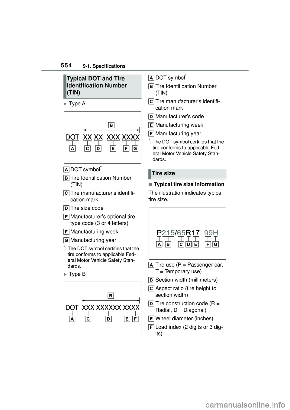
5549-1. Specifications
Ty p e ADOT symbol
*
Tire Identification Number
(TIN)
Tire manufacturer’s identifi-
cation mark
Tire size code
Manufacturer’s optional tire
type code (3 or 4 letters)
Manufacturing week
Manufacturing year
*: The DOT symbol certifies that the tire conforms to applicable Fed-
eral Motor Vehicle Safety Stan-
dards.
Ty p e B DOT symbol
*
Tire Identification Number
(TIN)
Tire manufacturer’s identifi-
cation mark
Manufacturer’s code
Manufacturing week
Manufacturing year
*:The DOT symbol ce
rtifies that the
tire conforms to applicable Fed-
eral Motor Vehicle Safety Stan-
dards.
■Typical tire size information
The illustration indicates typical
tire size.
Tire use (P = Passenger car,
T = Temporary use)
Section width (millimeters)
Aspect ratio (tire height to
section width)
Tire construction code (R =
Radial, D = Diagonal)
Wheel diameter (inches)
Load index (2 digits or 3 dig-
its)
Typical DOT and Tire
Identification Number
(TIN)
Tire size