change wheel TOYOTA COROLLA CROSS HYBRID 2023 User Guide
[x] Cancel search | Manufacturer: TOYOTA, Model Year: 2023, Model line: COROLLA CROSS HYBRID, Model: TOYOTA COROLLA CROSS HYBRID 2023Pages: 516, PDF Size: 15.96 MB
Page 226 of 516
2264-5. Using the driving support systems
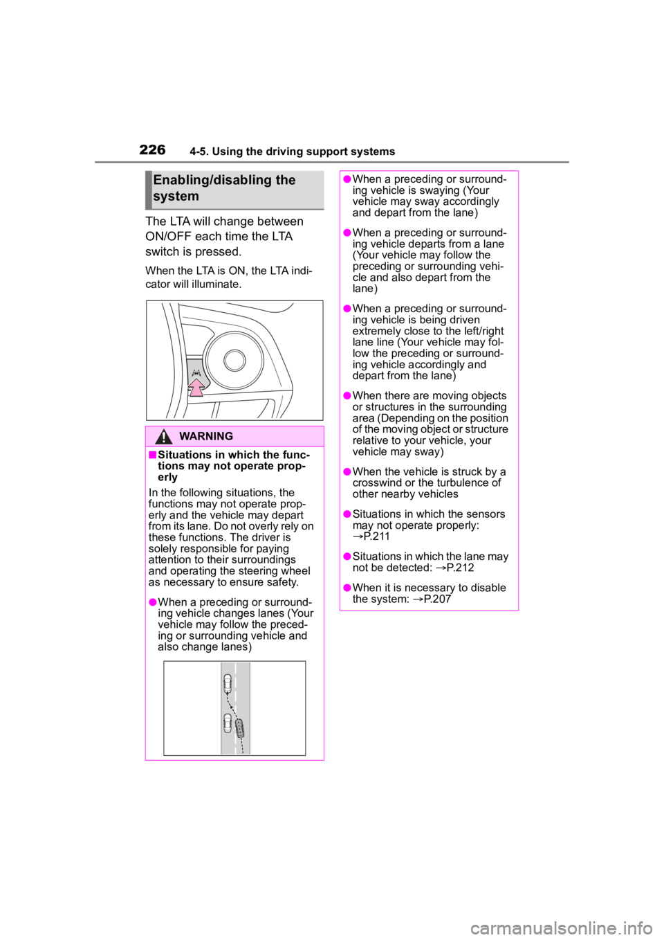
The LTA will change between
ON/OFF each time the LTA
switch is pressed.
When the LTA is ON, the LTA indi-
cator will illuminate.
Enabling/disabling the
system
WARNING
■Situations in which the func-
tions may not operate prop-
erly
In the following situations, the
functions may not operate prop-
erly and the vehicle may depart
from its lane. Do not overly rely on
these functions. The driver is
solely responsible for paying
attention to their surroundings
and operating the steering wheel
as necessary to ensure safety.
●When a preceding or surround-
ing vehicle changes lanes (Your
vehicle may follow the preced-
ing or surrounding vehicle and
also change lanes)
●When a preceding or surround-
ing vehicle is swaying (Your
vehicle may sway accordingly
and depart from the lane)
●When a preceding or surround-
ing vehicle departs from a lane
(Your vehicle may follow the
preceding or surrounding vehi-
cle and also depart from the
lane)
●When a preceding or surround-
ing vehicle is being driven
extremely close to the left/right
lane line (Your vehicle may fol-
low the preceding or surround-
ing vehicle accordingly and
depart from the lane)
●When there are moving objects
or structures in the surrounding
area (Depending on the position
of the moving object or structure
relative to your vehicle, your
vehicle may sway)
●When the vehicle is struck by a
crosswind or the turbulence of
other nearby vehicles
●Situations in which the sensors
may not operate properly:
P. 2 1 1
●Situations in which the lane may
not be detected: P.212
●When it is necessary to disable
the system: P.207
Page 230 of 516

2304-5. Using the driving support systems
This function is operable when all of
the following conditions are met:
• The vehicle speed is approxi-
mately 30 mph (50 km/h) or more.
Operation may be possible when
the vehicle speed is approximately
25 mph (40 km/h) or more if vehi-
cles, motorcycles, bicycles, or
pedestrians are detected near the
lane.
• The system reco gnizes a lane or
course
*. (When recognized on
only one side, the system will
operate only for the recognized
side.)
• The lane width is approximately 9.8 ft. (3 m) or more.
• The turn signal l ever is not being
operated. (Vehicles with BSM:
Except when a vehicle is detected
in the direction that the turn signal
lever is operated.)
• The vehicle is not being driven around a sharp curve.
• The vehicle is not accelerating or decelerating more than a certain
amount.
• The steering wheel is not being turned sufficiently to perform a
lane change.
*: Boundary between the asphalt
and grass, soil, etc., or structures,
such as a curb, guardrail, etc.
■Temporary cancellation of func-
tions
When the operating conditions are
no longer met, a function may be
temporarily canceled. However,
when the operation conditions are
met again, operation of the function
will automatically be restored.
( P.229)
■Operation of the lane departure
alert function/lane departure
prevention function
●Depending on the vehicle speed,
road conditions, lane departure
angle, etc., operation of the lane
departure prevention function may not be felt or the function may not
operate.
●Depending on the conditions, the
warning buzzer may operate even
if vibration is selected through a
customize setting.
●If a course* is not clear or straight,
the lane departure alert function or
lane departure prevention function
may not operate.
●The lane departure alert function
or lane departure prevention func-
tion may not operate if the system
judges that the vehicle is inten-
tionally being ste ered to avoid a
pedestrian or parked vehicle.
●Vehicles with BSM: It may not be
possible for the sys tem to judge if
there is danger of a collision with a
vehicle in an adjacent lane.
●The steering assist operation of
the lane departure prevention
function can be overridden by the
steering wheel operation of the
driver.
*: Boundary between the asphalt
and grass, soil, etc., or structures,
such as a curb, guardrail, etc.
■Hands off steering wheel warn-
ing operation
In the following si tuations, a mes-
sage urging the driver to operate the
steering wheel and an icon will be
displayed and a buzzer will sound to
warn the driver. When using the sys-
tem, make sure to grip the steering
wheel firmly, rega rdless of whether
the warning is operating or not.
●When the system determines that
the driver is not securely holding
Page 231 of 516
2314-5. Using the driving support systems
4
Driving
the steering wheel, or the steering
wheel is not being operated when
the steering assist operation of the
lane departure prevention function
is operating
The length of time that the warning
buzzer operates will become longer
as the frequency o f the steering
assist operating increases. If the
system judges that the steering
wheel has been operated, the warn-
ing buzzer will stop.
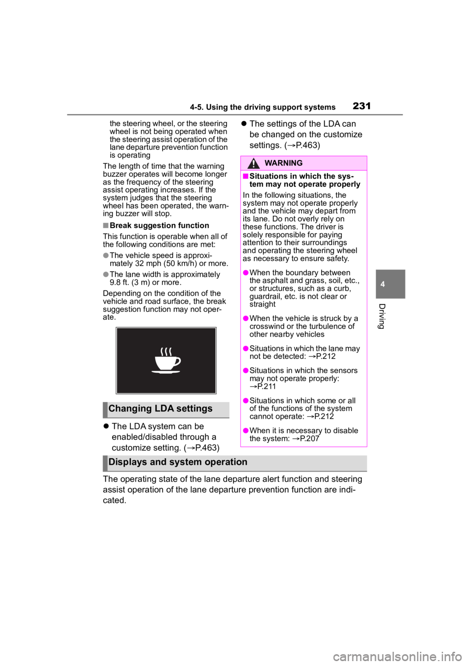
■Break suggestion function
This function is operable when all of
the following conditions are met:
●The vehicle speed is approxi-
mately 32 mph (50 km/h) or more.
●The lane width is approximately
9.8 ft. (3 m) or more.
Depending on the condition of the
vehicle and road surface, the break
suggestion functi on may not oper-
ate.
The LDA system can be
enabled/disabled through a
customize setting. ( P.463)
The settings of the LDA can
be changed on the customize
settings. ( P.463)
The operating state of the lane departure alert function and steering
assist operation of the lane departure prevention function are indi-
cated.
Changing LDA settings
WARNING
■Situations in which the sys-
tem may not ope rate properly
In the following situations, the
system may not operate properly
and the vehicle may depart from
its lane. Do not overly rely on
these functions. The driver is
solely responsible for paying
attention to their surroundings
and operating the steering wheel
as necessary to ensure safety.
●When the boundary between
the asphalt and grass, soil, etc.,
or structures, such as a curb,
guardrail, etc. is not clear or
straight
●When the vehicle is struck by a
crosswind or the turbulence of
other nearby vehicles
●Situations in which the lane may
not be detected: P.212
●Situations in which the sensors
may not operate properly:
P. 2 1 1
●Situations in which some or all
of the functions of the system
cannot operate: P.212
●When it is necessary to disable
the system: P.207
Displays and system operation
Page 242 of 516
2424-5. Using the driving support systems
and the system cannot provide
sufficient deceleration, such as
if a vehicle cuts in front of the
vehicle, a warning display will
flash and a buzzer will sound to
alert the driver. Depress the
brake pedal to ensure appropri-
ate vehicle-to-vehicle distance.
■Warnings may not occur
when
In the following situations, the
warning may not operate even
though the vehicle-to-vehicle
distance is short.
When the preceding vehicle is
traveling at the same speed
or faster than your vehicle
When the preceding vehicle is
traveling at an extremely low
speed
Immediately after the vehicle
speed has been set
When the accelerator pedal is
depressed
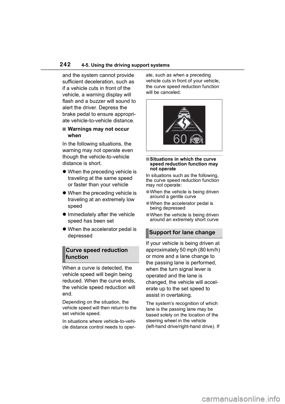
When a curve is detected, the
vehicle speed will begin being
reduced. When the curve ends,
the vehicle speed reduction will
end.
Depending on the situation, the
vehicle speed will then return to the
set vehicle speed.
In situations where vehicle-to-vehi-
cle distance control needs to oper- ate, such as when a preceding
vehicle cuts in front of your vehicle,
the curve speed reduction function
will be canceled.
■Situations in which the curve
speed reduction function may
not operate
In situations such as the following,
the curve speed reduction function
may not operate:
●When the vehicle is being driven
around a gentle curve
●When the accele rator pedal is
being depressed
●When the vehicle is being driven
around an extremely short curve
If your vehicle is being driven at
approximately 50 mph (80 km/h)
or more and a lane change to
the passing lane is performed,
when the turn signal lever is
operated and the lane is
changed, the vehicle will accel-
erate up to the set speed to
assist in overtaking.
The system’s recognition of which
lane is the passing lane may be
based solely on the location of the
steering wheel in the vehicle
(left-hand drive/right-hand drive). If
Curve speed reduction
function
Support for lane change
Page 250 of 516
2504-5. Using the driving support systems
Operation of this system is sep-
arated into 4 control states.
Emergency Driving
Stop System
The emergency driving stop
system is a system which
automatically decelerates
and stops the vehicle within
its lane if the driver
becomes unable to continue
driving the vehicle, such as
if they have suffered a medi-
cal emergency, etc.
During LTA (Lane Tracing
Assist) control, if the sys-
tem does not detect driving
operations, such as if the
driver is not holding the
steering wheel, and deter-
mines the driver is not
responsive, the vehicle will
be decelerated and stopped
within its current lane to
help avoid a collision or
reduce the impact of a colli-
sion.
WARNING
■For safe use
●Driving safely is solely the
responsibility of the driver. Pay
careful attention to the sur-
rounding conditions in order to
ensure safe driving. The emer-
gency driving stop system is
designed to provide support in
an emergency where it is diffi-
cult for the driver to continue
driving, such as if they have had
a medical emergency. It is not
designed to support driving
while drowsy or in poor physical
health, or inattentive driving.
●Although the emergency driv-
ing stop system is designed to
decelerate the vehicle within its
lane to help avoid or help
reduce the impact of a collision
if the system determines that it
is difficult for the driver to con-
tinue driving, its effectiveness
may change according to vari-
ous conditions. Therefore, it
may not always be able to
achieve the same level of per-
formance. Also, if the operating
conditions are not met, this
function will not operate.
●After the emergency driving
stop system operates, if driving
becomes possible again, imme-
diately begin driving again or, if
necessary, park the vehicle on
the shoulder of the road and set
a warning reflecto r and flare to
warn other drivers of your
stopped vehicle.
●After this system operates, pas-
sengers should attend to the
driver as necessary and take
appropriate hazard prevention
measures, such as moving to a
place where safety can be
ensured, such as the shoulder
of the road or behind a guard-
rail.
●This system detects the condi-
tion of the driver through the
operation of the steering wheel.
This system may operate if the
driver is aware but intentionally
and continuously does not oper-
ate the vehicle. Also, the system
may not operate if it cannot
determine that the driver is not
responsive, such as if they are
leaning on the steering wheel.
Summary of the system
Page 288 of 516
2884-5. Using the driving support systems
WARNING
●When driving over bumps in the
road
●When driving over roads with
potholes or uneven surfaces
■TRAC/VSC may not operate
effectively when
Directional control and power may
not be achievable while driving on
slippery road surfaces, even if the
TRAC/VSC system is operating.
Drive the vehicle carefully in con-
ditions where stability and power
may be lost.
■Active Cornering Assist does
not operate effectively when
●Do not overly rely on Active
Cornering Assist. Active Corner-
ing Assist may not operate
effectively when accelerating
down slopes or driving on slip-
pery road surfaces.
●When Active Cornering Assist
frequently operates, Active Cor-
nering Assist may temporarily
stop operating to ensure proper
operation of the brakes, TRAC
and VSC.
■Hill-start assist control does
not operate effectively when
●Do not overly rely on hill-start
assist control. Hill-start assist
control may not operate effec-
tively on steep inclines and
roads covered with ice.
●Unlike the parking brake,
hill-start assist control is not
intended to hold the vehicle sta-
tionary for an extended period
of time. Do not attempt to use
hill-start assist control to hold
the vehicle on an incline, as
doing so may lead to an acci-
dent.
■When the TRAC/ABS/VSC is
activated
The slip indicator light flashes.
Always drive carefully. Reckless
driving may cause an accident.
Exercise particula r care when the
indicator light flashes.
■When the TRAC/VSC systems
are turned off
Be especially careful and drive at
a speed appropriate to the road
conditions. As these are the sys-
tems to help ensure vehicle stabil-
ity and driving force, do not turn
the TRAC/VSC systems off
unless necessary.
■Replacing tires
Make sure that all tires are of the
specified size, brand, tread pat-
tern and total load capacity. In
addition, make sure that the tires
are inflated to the recommended
tire inflation p ressure level.
The ABS, TRAC and VSC sys-
tems will not functi on correctly if
different tires are installed on the
vehicle.
Contact your Toyota dealer for fur-
ther information when replacing
tires or wheels.
■Handling of tires and the sus-
pension
Using tires with any kind of prob-
lem or modifying the suspension
will affect the driving assist sys-
tems, and may cause a system to
malfunction.
■Secondary Collision Brake
Do not rely solely upon the Sec-
ondary Collision Brake. This sys-
tem is designed to help reduce
the possibility of further damage
due to a secondary collision, how-
ever, that effect changes accord-
ing to various conditions. Overly
relying on the system may result
in death or serious injury.
Page 294 of 516
2944-6. Driving tips
When driving your vehicle
off-road, please observe the fol-
lowing precautions to ensure
your driving enjoyment and to
help prevent the closure of
areas to off-road vehicles:
Drive your vehicle only in
areas where off-road vehicles
are permitted to travel.
Respect private property. Get
owner’s permission before
entering private property.
Do not enter areas that are
closed. Honor gates, barriers
and signs that restrict travel.
Stay on established roads.
When conditions are wet,
driving techniques should be
changed or travel delayed to
prevent damage to roads.
■Additional information for
off-road driving
For owners in U.S. mainland,
Hawaii and Puerto Rico:
To obtain additional information per-
taining to driving your vehicle
off-road, consult the following orga-
nizations.
●State and Local Parks and Recre-
ation Departments
●State Motor Vehicle Bureau
●Recreational Vehicle Clubs
●U.S. Forest Service and Bureau of
Land Management
Off-road drivingWARNING
■Off-road driving precautions
Always observe t he following pre-
cautions to minim ize the risk of
death, serious injury or damage to
your vehicle:
●Drive carefully when off the
road. Do not take unnecessary
risks by driving in dangerous
places.
●Do not grip the steering wheel
spokes when driving off-road. A
bad bump could jerk the wheel
and injure your hands. Keep
both hands and especially your
thumbs on the ou tside of the
rim.
●Always check your brakes for
effectiveness immediately after
driving in sand, mud, water or
snow.
●After driving through tall grass,
mud, rock, sand, rivers, etc.,
check that there is no grass,
bush, paper, rags, stone, sand,
etc. adhering or trapped on the
underbody. Clear off any such
matter from the underbody. If
the vehicle is used with these
materials trapped or adhering to
the underbody, a breakdown or
fire could occur.
●When driving off-road or in rug-
ged terrain, do not drive at
excessive speeds, jump, make
sharp turns, strike objects, etc.
This may cause loss of control
or vehicle rollover causing
death or serious injury. You are
also risking expensive damage
to your vehicle’s suspension
and chassis.
Page 362 of 516

3626-3. Do-it-yourself maintenance
4Press or to select
“Vehicle Settings” and then
press and hold .
5 Press or to select
“TPWS setting” and then
press .
6 Press or to select
“Pressure unit setting”.
7 Press or to select the
desired unit and then press
.
■Routine tire inflation pressure
checks
The tire pressure warning system
does not replace routine tire inflation
pressure checks. Make sure to
check tire inflation pressure as part
of your routine of daily vehicle
checks.
■Tire inflation pressure
●It may take a few minutes to dis-
play the tire inflation pressure
after the power switch is turned to
ON. It may also take a few min-
utes to display the tire inflation
pressure after inflation pressure
has been adjusted.
●Tire inflation pressure changes
with temperature.
The displayed values may also be
different from th e values mea-
sured using a tire pressure gauge.
■Situations in which the tire
pressure warning system may
not operate properly
●In the following cases, the tire
pressure warning system may not
operate properly.
• If non-genuine Toyota wheels are
used.
• A tire has been replaced with a tire that is not an OE (Original
Equipment) tire.
• A tire has been replaced with a
tire that is not of the specified size.
• Tire chains, etc. are equipped.
• An auxiliary-support ed run-flat tire
is equipped.
• If a window tint that affects the radio wave signals is installed.
• If there is a lot of snow or ice on the vehicle, particularly around the
wheels or wheel housings.
• If the tire inflation pressure is extremely higher than the speci-
fied level.
• If wheel withou t tire pressure
warning valves and transmitters
are used.
• If the ID code on the tire pressure warning valves and transmitters is
not registered in the tire pressure
warning computer.
●Performance may be affected in
the following situations.
• Near a TV tower, electric power plant, gas station, radio station,
large display, airpo rt or other facil-
ity that generates strong radio
waves or electrical noise
• When carrying a portable radio, cellular phone, cordless phone or
other wireless communication
device
●If tire position information is not
correctly displayed due to the
radio wave conditions, the display
may be corrected by driving and
changing the radio wave condi-
tions.
●When the vehicle is parked, the
time taken for the warning to start
or go off could be extended.
●When tire inflation pressure
declines rapidly for example when
a tire has burst, the warning may
not function.
■Warning performance of the tire
pressure warning system
The warning of the tire pressure
warning system w ill change in
accordance with the conditions
Page 367 of 516
3676-3. Do-it-yourself maintenance
6
Maintenance and care
Press or to select “Tyre
Set Switching” and then press .
6 4.2-inch display meter:
Press or to select
“Register New Valve / ID” and
then press .
7-inch display meter:
Press or to select “Reg-
ister New Valve / ID” and then
press .
7 4.2-inch display meter:
Press or to select
“Tire Set 1” or “Tire Set 2”.
Then press .
7-inch display meter:
Press or to select “Tire
Set 1” or “Tire Set 2”. Then
press .
The change wheel set mode is acti-
vated and registration is started.
Then a message w ill be displayed
on the multi-information display.
When registration is being per-
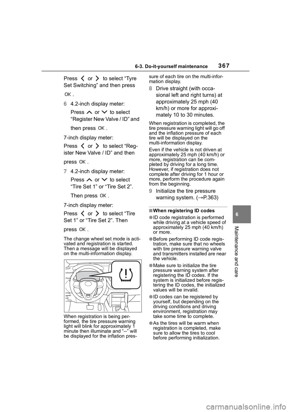
formed, the tire pressure warning
light will blink for approximately 1
minute then illumi nate and “--” will
be displayed for the inflation pres- sure of each tire o
n the multi-infor-
mation display.
8 Drive straight (with occa-
sional left and right turns) at
approximately 25 mph (40
km/h) or more for approxi-
mately 10 to 30 minutes.
When registration is completed, the
tire pressure warni ng light will go off
and the inflation pressure of each
tire will be disp layed on the
multi-information display.
Even if the vehicle is not driven at
approximately 25 mph (40 km/h) or
more, registration can be com-
pleted by driving for a long time.
However, if registration does not
complete after driving for 1 hour or
more, perform the p rocedure again
from the beginning.
9 Initialize the tire pressure
warning system. ( P.363)
■When registering ID codes
●ID code registrati on is performed
while driving at a vehicle speed of
approximately 25 mph (40 km/h)
or more.
●Before performing ID code regis-
tration, make sure that no wheels
with tire pressure warning valve
and transmitters installed are near
the vehicle.
●Make sure to initi alize the tire
pressure warning system after
registering the ID codes. If the
system is initialized before regis-
tering the ID codes , the initialized
values will be invalid.
●ID codes can be registered by
yourself, but depending on the
driving conditions and driving
environment, registration may
take some time to complete.
●As the tires will be warm when
registration is completed, make
sure to allow the tires to cool
before performin g initialization.
Page 369 of 516
3696-3. Do-it-yourself maintenance
6
Maintenance and care
change of wheel set only if a
second wheel set has been
registered. If no second wheel
set has been registered, no
change will be made when
selecting this function in the
menu.
Only a change between both
registered wheel set is possi-
ble, mixing between these
wheel sets is not supported.
■How to change between
wheel sets
1 Have the vehicle fitted with
the preferred wheel set.
2 4.2-inch display meter:
Press or of the meter
control switch to select .
7-inch display meter:
Press or of the meter
control switch to select .
3 4.2-inch display meter:
Press or to select
“Vehicle Settings” and then
press and hold .
7-inch display meter:
Press or to select “Vehi-
cle Settings” and then press and
hold .
4 4.2-inch display meter:
Press or to select
“TPWS setting” and then
press .
7-inch display meter: Press or to select
“TPWS setting” and then press
.
5 4.2-inch display meter:
Press or to select
“Tyre Set Switching” and then
press .
7-inch display meter:
Press or to select “Tyre
Set Switching” and then press .
6 4.2-inch display meter:
Press or to select
“Register New Valve / ID” and
then press .
7-inch display meter:
Press or to select “Reg-
ister New Valve / ID” and then
press .
7 4.2-inch display meter:
Press or to select
“Tire Set 1” or “Tire Set 2”.
Then press .
7-inch display meter:
Press or to select “Tire
Set 1” or “Tire Set 2”. Then
press .
Afterward, the tire pressure warning
light turns on afte r flashing for 1