ECU TOYOTA COROLLA HATCHBACK 2023 Repair Manual
[x] Cancel search | Manufacturer: TOYOTA, Model Year: 2023, Model line: COROLLA HATCHBACK, Model: TOYOTA COROLLA HATCHBACK 2023Pages: 436, PDF Size: 8.72 MB
Page 348 of 436
3487-2. Steps to take in an emergency
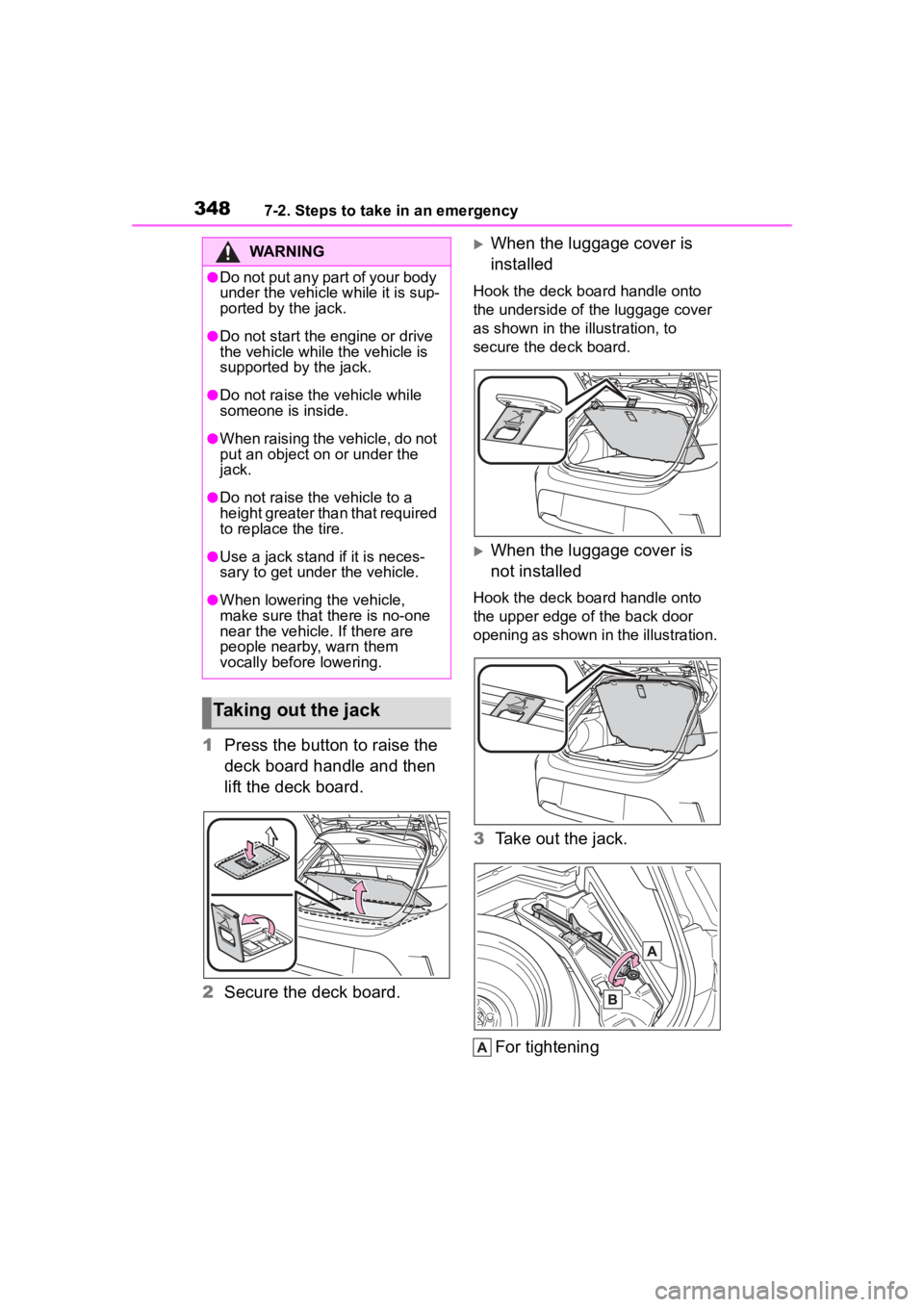
1Press the button to raise the
deck board handle and then
lift the deck board.
2 Secure the deck board.
When the luggage cover is
installed
Hook the deck board handle onto
the underside of the luggage cover
as shown in the illustration, to
secure the deck board.
When the luggage cover is
not installed
Hook the deck board handle onto
the upper edge of the back door
opening as shown in the illustration.
3Take out the jack.
For tightening
WARNING
●Do not put any part of your body
under the vehicle while it is sup-
ported by the jack.
●Do not start the engine or drive
the vehicle while the vehicle is
supported by the jack.
●Do not raise the vehicle while
someone is inside.
●When raising the vehicle, do not
put an object on or under the
jack.
●Do not raise the vehicle to a
height greater than that required
to replace the tire.
●Use a jack stand if it is neces-
sary to get under the vehicle.
●When lowering the vehicle,
make sure that there is no-one
near the vehicle. If there are
people nearby, warn them
vocally before lowering.
Taking out the jack
Page 349 of 436
3497-2. Steps to take in an emergency
7
When trouble arises
For loosening
1 Secure the deck board.
( P.348)
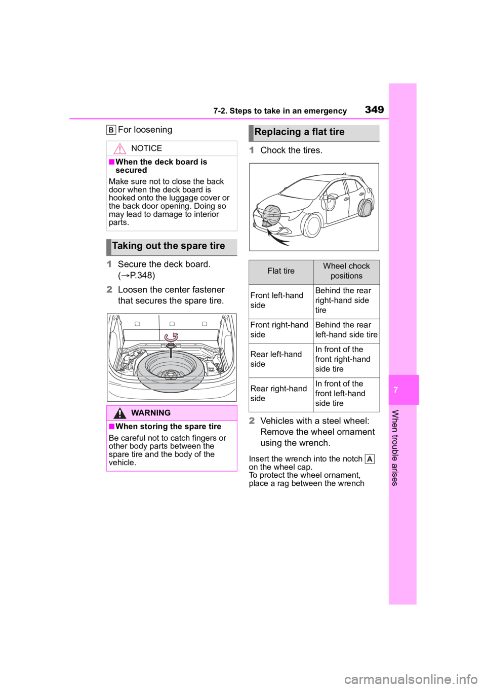
2 Loosen the center fastener
that secures the spare tire. 1
Chock the tires.
2 Vehicles with a steel wheel:
Remove the wheel ornament
using the wrench.
Insert the wrench i nto the notch
on the wheel cap.
To protect the wh eel ornament,
place a rag between the wrench
NOTICE
■When the deck board is
secured
Make sure not to close the back
door when the deck board is
hooked onto the luggage cover or
the back door opening. Doing so
may lead to damage to interior
parts.
Taking out the spare tire
WARNING
■When storing the spare tire
Be careful not to catch fingers or
other body parts between the
spare tire and the body of the
vehicle.
Replacing a flat tire
Flat tireWheel chock positions
Front left-hand
sideBehind the rear
right-hand side
tire
Front right-hand
sideBehind the rear
left-hand side tire
Rear left-hand
sideIn front of the
front right-hand
side tire
Rear right-hand
sideIn front of the
front left-hand
side tire
Page 353 of 436
3537-2. Steps to take in an emergency
7
When trouble arises
WARNING
■When using the compact
spare tire
●Remember that the compact
spare tire provided is specifi-
cally designed for use with your
vehicle. Do not use your com-
pact spare tire on another vehi-
cle.
●Do not use more than one com-
pact spare tires simultaneously.
●Replace the compact spare tire
with a standard tire as soon as
possible.
●Avoid sudden acceleration,
abrupt steering, sudden brak-
ing and shifting operations that
cause sudden engine braking.
■When the compact spare tire
is attached
The vehicle speed may not be
correctly detecte d, and the follow-
ing systems may not operate cor-
rectly:
• ABS & Brake assist
• VSC
• TRAC
• Automatic High Beam
• Dynamic radar cruise control
• EPS
• PCS (Pre-Collision System)
• LDA (Lane Departure Alert)
• LTA (Lane Tracing Assist)
• BSM (if equipped)
• RCTA (if equipped)
• SEA (if equipped)
• Tire pressure warning system
• Navigation system (if equipped)
■Speed limit when using the
compact spare tire
Do not drive at speeds in excess
of 50 mph (80 km /h) when a com-
pact spare tire is installed on the
vehicle.
The compact spare tire is not
designed for driving at high
speeds. Failure to observe this
precaution may lead to an acci-
dent causing death or serious
injury.
■After using the tools and jack
Before driving, ma ke sure all the
tools and jack are securely in
place in their storage location to
reduce the possibility of personal
injury during a collision or sudden
braking.
NOTICE
■Be careful when driving over
bumps with the compact
spare tire installed on the
vehicle
The vehicle becomes lower when
driving with the compact spare tire
compared to when driving with
standard tires. Be careful when
driving over uneven road sur-
faces.
Page 360 of 436

3607-2. Steps to take in an emergency
recharge the battery of your
vehicle.
5 Open and close any of the
doors of your vehicle with the
engine switch OFF.
6 Maintain the engine speed of
the second vehicle and start
the engine of your vehicle by
turning the engine switch to
ON.
7 Once the vehicle’s engine
has started, remove the
jumper cables in the exact
reverse order from which
they were connected.
Once the engine starts, have the
vehicle inspected at your Toyota
dealer as soon as possible.
■Starting the engine when the
battery is discharged
The engine cannot be started by
push-starting.
■To prevent battery discharge
●Turn off the headlights and the
audio system while the engine is
off.
●Turn off any unnecessary electri-
cal components when the vehicle
is running at a low speed for an
extended period, such as in heavy
traffic.
■When the battery is removed or
discharged
●Information stor ed in the ECU is
cleared. When the battery is
depleted, have the vehicle
inspected at you r Toyota dealer.
●Some systems may require initial-
ization. ( P.395)
■When removing the battery ter-
minals
When the battery terminals are
removed, the information stored in
the ECU is cleared. Before remov-
ing the battery term inals, contact
your Toyota dealer.
■Charging the battery
The electricity stored in the battery
will discharge grad ually even when
the vehicle is not in use, due to nat-
ural discharge and the draining
effects of certain electrical appli-
ances. If the vehicle is left for a long
time, the battery may discharge,
and the engine may be unable to
start. (The battery recharges auto-
matically during driving.)
■When recharging or replacing
the battery
●In some cases, it may not be pos-
sible to unlock the doors using the
smart key system when the bat-
tery is discharged. Use the wire-
less remote control or the
mechanical key to lock or unlock
the doors.
●The engine may not start on the
first attempt after the battery has
recharged but will start normally
after the second attempt. This is
not a malfunction.
●The engine switch mode is memo-
rized by the vehicle. When the
battery is reconnected, the system
will return to the mode it was in
before the bat tery was dis-
charged. Before disconnecting the
battery, turn the engine switch off.
If you are unsure what mode the
engine switch wa s in before the
battery discharged, be especially
careful when reconnecting the
battery.
■When replacing the battery
●Use a battery that conforms to
European regulations.
●Use a battery that the case size is
same as the previous one (LN1),
20 hour rate capacity (20HR) is
Page 361 of 436
3617-2. Steps to take in an emergency
7
When trouble arises
equivalent (45Ah) or greater, and
performance rating (CCA) is
equivalent (307A) or greater.
• If the sizes differ, the battery can- not be properly secured.
• If the 20 hour rate capacity is low,
even if the time period where the
vehicle is not used is a short time,
the battery may discharge and the
engine may not be able to start.
●For details, consu lt your Toyota
dealer.
WARNING
■When removing the battery
terminals
Always remove the negative (-)
terminal first. If the positive (+) ter-
minal contacts any metal in the
surrounding area when the posi-
tive (+) terminal is removed, a
spark may occur, l eading to a fire
in addition to electrical shocks
and death or serious injury.
■Avoiding battery fires or
explosions
Observe the following precautions
to prevent accidentally igniting the
flammable gas that may be emit-
ted from the battery:
●Make sure each jumper cable is
connected to the correct termi-
nal and that it is not unintention-
ally in contact with any other
than the intended terminal.
●Do not allow the other end of
the jumper cable connected to
the “+” terminal to come into
contact with any other parts or
metal surfaces in the area, such
as brackets or unpainted metal.
●Do not allow the + and - clamps
of the jumper cables to come
into contact with each other.
●Do not smoke, use matches,
cigarette lighters or allow open
flame near the battery.
■Battery precautions
The battery contains poisonous
and corrosive acidic electrolyte,
while related parts contain lead
and lead compounds. Observe
the following precautions when
handling the battery:
●When working with the battery,
always wear safety glasses and
take care not to allow any bat-
tery fluids (acid) to come into
contact with skin, clothing or the
vehicle body.
●Do not lean over the battery.
●In the event that battery fluid
comes into contact with the skin
or eyes, immediately wash the
affected area with water and
seek medical attention. Place a
wet sponge or cloth over the
affected area until medical
attention can be received.
●Always wash your hands after
handling the battery support,
terminals, and other bat-
tery-related parts.
●Do not allow children near the
battery.
NOTICE
■When handling jumper cables
When connecting the jumper
cables, ensure that they do not
become entangled in the cooling
fan or engine drive belt.
Page 384 of 436
3848-1. Specifications
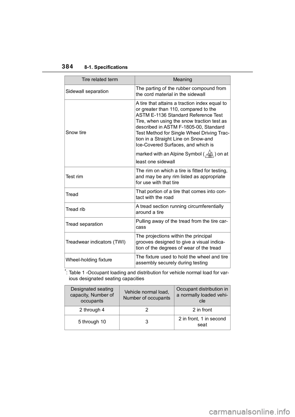
*: Table 1 -Occupant loading and distribution for vehicle normal load for var-
ious designated seating capacities
Sidewall separationThe parting of the rubber compound from
the cord materia l in the sidewall
Snow tire
A tire that attains a traction index equal to
or greater than 110, compared to the
ASTM E-1136 Standard Reference Test
Tire, when using the snow traction test as
described in ASTM F-1805-00, Standard
Test Method for Single Wheel Driving Trac-
tion in a Straight Line on Snow-and
Ice-Covered Surfaces, and which is
marked with an Alpine Symbol ( ) on at
least one sidewall
Te s t r i m
The rim on which a tire is fitted for testing,
and may be any rim lis ted as appropriate
for use with that tire
TreadThat portion of a tire that comes into con-
tact with the road
Tread ribA tread section running circumferentially
around a tire
Tread separationPulling away of the tread from the tire car-
cass
Treadwear indicators (TWI)
The projections wit hin the principal
grooves designed to g ive a visual indica-
tion of the degrees of wear of the tread
Wheel-holding fixtureThe fixture used to hol d the wheel and tire
assembly securely during testing
Tire related termMeaning
Designated seating
capacity, Number of occupantsVehicle normal load,
Number of occupantsOccupant distribution in a normally loaded vehi- cle
2 through 422 in front
5 through 1032 in front, 1 in second seat
Page 389 of 436
3898-2. Customization
8
Vehicle specifications
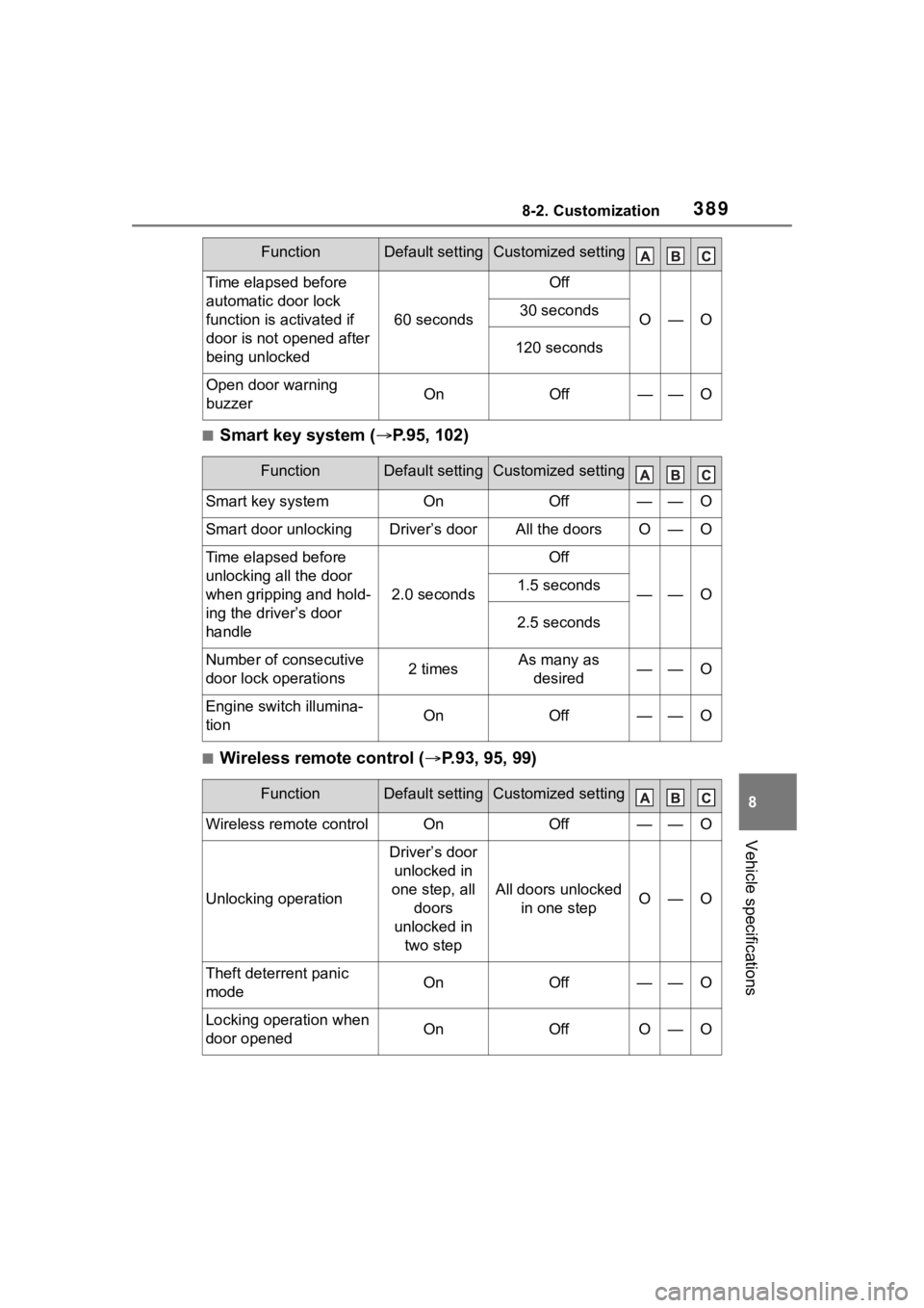
■Smart key system (P.95, 102)
■Wireless remote control ( P.93, 95, 99)
Time elapsed before
automatic door lock
function is activated if
door is not opened after
being unlocked
60 seconds
Off
O—O30 seconds
120 seconds
Open door warning
buzzerOnOff——O
FunctionDefault settingCustomized setting
Smart key systemOnOff——O
Smart door unlockingDriver’s doorAll the doorsO—O
Time elapsed before
unlocking all the door
when gripping and hold-
ing the driver’s door
handle
2.0 seconds
Off
——O1.5 seconds
2.5 seconds
Number of consecutive
door lock operations2 timesAs many as
desired——O
Engine switch illumina-
tionOnOff——O
FunctionDefault settingCustomized setting
Wireless remote controlOnOff——O
Unlocking operation
Driver’s door unlocked in
one step, all doors
unlocked in two step
All doors unlocked in one stepO—O
Theft deterrent panic
modeOnOff——O
Locking operation when
door openedOnOffO—O
FunctionDefault settingCustomized setting
Page 399 of 436
3999-1. For owners
9
For owners
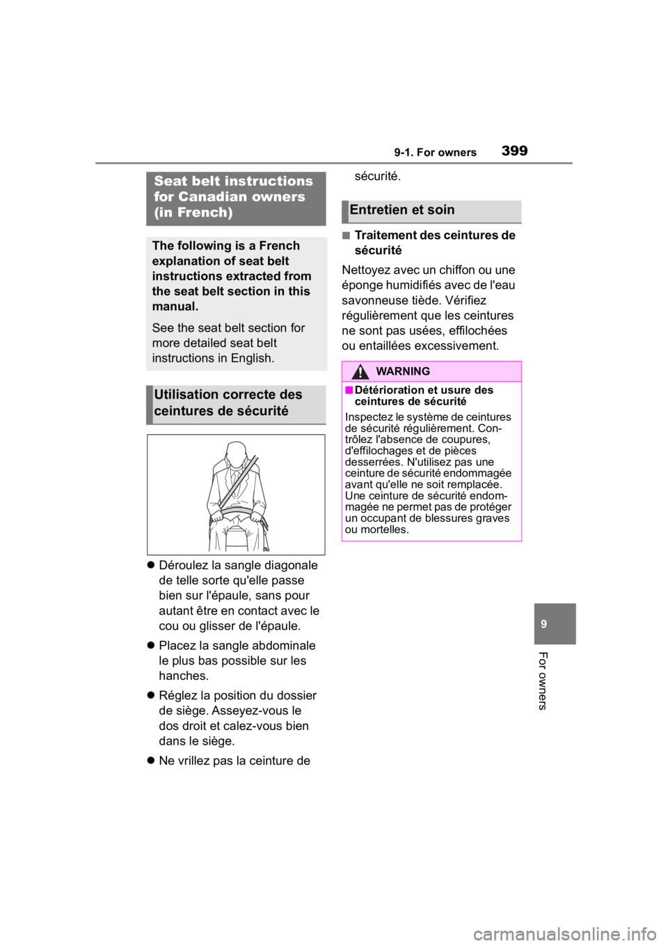
Déroulez la sangle diagonale
de telle sorte qu'elle passe
bien sur l'épaule, sans pour
autant être en contact avec le
cou ou glisser de l'épaule.
Placez la sangle abdominale
le plus bas possible sur les
hanches.
Réglez la position du dossier
de siège. Asseyez-vous le
dos droit et calez-vous bien
dans le siège.
Ne vrillez pas la ceinture de sécurité.
■Traitement des ceintures de
sécurité
Nettoyez avec un chiffon ou une
éponge humidifiés avec de l'eau
savonneuse tiède. Vérifiez
régulièrement que les ceintures
ne sont pas usées, effilochées
ou entaillées excessivement.
Seat belt instructions
for Canadian owners
(in French)
The following is a French
explanation of seat belt
instructions extracted from
the seat belt section in this
manual.
See the seat belt section for
more detailed seat belt
instructions in English.
Utilisation correcte des
ceintures de sécurité
Entretien et soin
WARNING
■Détérioration et usure des
ceintures de sécurité
Inspectez le système de ceintures
de sécurité régulièrement. Con-
trôlez l'absence de coupures,
d'effilochages et de pièces
desserrées. N'ut ilisez pas une
ceinture de sécurité endommagée
avant qu'elle ne soit remplacée.
Une ceinture de sécurité endom-
magée ne permet pas de protéger
un occupant de blessures graves
ou mortelles.
Page 401 of 436
4019-1. For owners
9
For owners
Coussins gonflables latéraux et rideaux SRS
Coussins gonflables latéraux avant SRS
Participent à la protection du torse des occupants de siège ava nt
Coussins gonflables latéraux arrière SRS
Participent à la protection du torse des occupants des sièges latéraux
arrière
Coussins gonflables rideaux SRS
• Participent principalement à la protection de la tête des occu pants des
sièges latéraux
• Peut contribuer à empêc her les occupants d’être éjectés du véhicule en
cas de tonneau
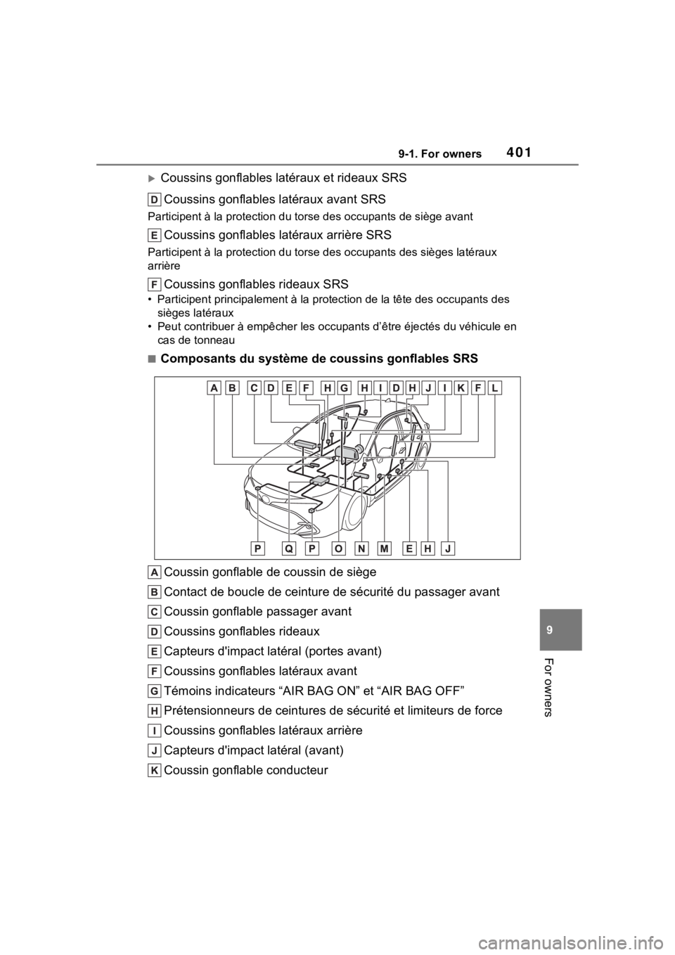
■Composants du système de coussins gonflables SRS
Coussin gonflable de coussin de siège
Contact de boucle de ceinture de sécurité du passager avant
Coussin gonflable passager avant
Coussins gonflables rideaux
Capteurs d'impact latéral (portes avant)
Coussins gonflables latéraux avant
Témoins indicateurs “AIR BAG ON” et “AIR BAG OFF”
Prétensionneurs de ceintures de sécurité et limiteurs de force
Coussins gonflables latéraux arrière
Capteurs d'impact latéral (avant)
Coussin gonflable conducteur
Page 402 of 436
4029-1. For owners
Contact de boucle de ceinture de sécurité conducteur
Capteur de position du siège conducteur
Coussin gonflable de genoux du conducteur
Témoin d'avertissement SRS
Capteurs d'impact avant
Ensemble de capteurs de coussins gonflables
Votre véhicule est équipé de COUSSINS GONFLABLES INTELLI-
GENTS conçus selon les normes de sécurité américaines applica-
bles aux véhicules à moteur (FMVSS208). L'ensemble de capteurs
de coussins gonflables (ECU) régule le déploiement des coussins
gonflables sur la base des informa tions qu'il reçoit des capteurs,
etc., indiqués ci-dessus dans le schéma illustrant les composants du
système. Parmi ces informations figurent la gravité du choc et l'occu-
pation du véhicule par les passagers. Le déploiement rapide des
coussins gonflables est obtenu au moyen d'une réaction chimique
dans les dispositifs pyrotechniques, qui produit un gaz inoffen sif per-
mettant d'amortir le mouvement des occupants.
WARNING
■Précautions relatives aux
coussins gonflables SRS
Respectez les précautions suiva-
ntes concernant les coussins gon-
flables SRS.
Le non-respect de ces précau-
tions peut occasionner des bless-
ures graves, voire mortelles.
●Le conducteur et tous les pas-
sagers du véhicule doivent por-
ter correctement leur ceinture
de sécurité.
Les coussins gonflables SRS
sont des disposit ifs supplémen-
taires à utiliser avec les cein-
tures de sécurité.