light TOYOTA COROLLA HATCHBACK 2023 Manual Online
[x] Cancel search | Manufacturer: TOYOTA, Model Year: 2023, Model line: COROLLA HATCHBACK, Model: TOYOTA COROLLA HATCHBACK 2023Pages: 436, PDF Size: 8.72 MB
Page 182 of 436

1824-5. Using the driving support systems
The LDA system warns the
driver if the vehicle may deviate
from the current lane or course
*,
and also can slightly operate the
steering wheel to help avoid
deviation from the lane or
course
*.
The front camera is used to
detect lane lines or a course
*.
*: Boundary between the asphalt and grass, soil, etc., or structures,
such as a curb, guardrail, etc.
■Lane departure alert func-
tion
When the system determines
that the vehicle might depart
from its lane or course
*, a warn-
ing is displayed on a display,
and either a warning buzzer will
sound or the steering wheel will
vibrate to alert the driver.
Check the area around your vehicle
and carefully operate the steering
wheel to move the vehicle back to
the center of the lane or course
*.
Vehicles with BSM: If the system
determines that the vehicle may
collide with a vehicle in an adjacent
lane, the lane de parture alert will
operate even if the turn signals are
operating.
*: Boundary between the asphalt and grass, soil, etc., or structures, such as a curb,
guardrail, etc.
■Lane departure prevention
function
If the system determines that
the vehicle is likely to depart
from its lane or course
*, it pro-
vides assistance through steer-
ing wheel operations to help
avoid deviation from the lane or
course.
If the system determines that the
steering wheel has not been oper-
ated for a certain amount of time or
the steering wheel is not being
firmly gripped, a warning message
may be displayed and a warning
buzzer may sound to alert the
driver.
Vehicles with BSM: If the system
determines that the vehicle may
collide with a vehicl e in an adjacent
lane, the lane departure prevention
function will operate even if the turn
signals are operating.
LDA (Lane Depar ture
Alert)
Basic functions
Page 190 of 436
1904-5. Using the driving support systems
WARNING
●When a detectable object is
approaching your vehicle
●When your vehicle or a detect-
able object is wandering
●When the movement of a
detectable object changes
(change in direction, sudden
acceleration or deceleration,
etc.)
●When suddenly approaching a
detectable object
●When a preceding vehicle or
motorcycle is not directly in front
of your vehicle
●When there is a structure above
a detectable object
●When part of a detectable
object is hidden by another
object (large luggage, umbrella,
guardrail, etc.)
●When multiple detectable
objects are overlapping
●When a bright light, such as the
sun or headlights of another
vehicle, is reflecting off of the
detectable object
●When the detectable object is
white and looks extremely bright
●When the color or brightness of
the detectable object causes it
to blend in with its surroundings
●When a detectable object cuts
in front of or emerges from
beside a vehicle
●When approaching a vehicle
ahead which is perpendicular or
at an angle to the vehicle, or is
facing the vehicle
●If a parked vehicle is perpendic-
ular or at an angle to the vehicle
●When a bicycle is a child sized
bicycle, is carrying a large load,
is carrying an extra passenger,
or has an unusual shape (bicy-
cles equipped with a child seat,
tandem bicycles, etc.)
●When a pedestrian or bicyclist is
shorter than app roximately 3.2
ft. (1 m) or talle r than approxi-
mately 6.5 ft. (2 m)
●When the silhouette of a pedes-
trian or bicyclist is unclear (such
as when they are wearing a
raincoat, long skirt, etc.)
●When a pedestrian or bicyclist is
bending forward or squatting
●When a pedestrian or bicyclist is
moving at high speed
●When a pedestrian is pushing a
stroller, wheelchair, bicycle or
other vehicle
●When a detectable object
blends in with the surrounding
area, such as when it is dim (at
dawn or dusk) or dark (at night,
in a tunnel, etc.)
●When the lane width is 13.1 ft.
(4 m) or more
●When the lane width is 8.2 ft.
(2.5 m) or less
●When the vehicle has not been
driven for a certain amount of
time after the engine was
started
●While turning left or right or a
few seconds after turning left or
right
●While changing lanes or a few
seconds after changing lanes
●When entering a curve, driving
around a curve and a few sec-
onds after driving around a
curve
Page 195 of 436

1954-5. Using the driving support systems
4
Driving
Constant speed cruising:
When there are no vehicles ahead
The vehicle drives at the speed set by the driver.
If the set vehicle speed is exceeded while driving down a hill, the set vehicle
speed display will blin k and a buzzer will sound.
Deceleration and follow-up cruising
When a preceding vehicle driving slower than the set vehicle
speed is detected
When a vehicle is detected driving ahead of your vehicle, the v ehicle auto-
matically decelerates and if a greater reduction in vehicle spe ed is neces-
sary, the brakes are applied (the stop lights will come on at t his time). The
vehicle is controlled to maintai n the vehicle-to-vehicle distance set by the
driver, in accordance with changes in the speed of the precedin g vehicle. If
vehicle deceleration is not sufficient and the vehicle approaches the vehicle
ahead, the approach wa rning will sound.
Acceleration
When there are no longer any preceding vehicles driving slower
than the set vehicle speed
The vehicle accelerates until th e set vehicle speed is reached and then
resumes constant speed cruising.
Starting off:
If a preceding vehicle stops, the vehicle will also stop (contr olled
stop). After the preceding vehicle starts off, pressing the “RES”
switch or depressing the accelerator pedal will resume follow-u p
cruising (start off operation). If a start off operation is not per-
Basic functions
Page 205 of 436
2054-5. Using the driving support systems
4
Driving
Through control state “warning
phase 1” and “warning phase 2”,
the system determines if the
driver is aware and responsive
while outputting a warning and
controlling the vehicle speed. If
the system determines the
driver is not responsive, it will
operate in control state “deceler-
ation stop phase” and “stop hold
phase” and decelerate and stop
the vehicle. It will then operate
continuously in “stop hold
phase”.
■Operating conditions
This system opera tes when all of
the following cond itions are met:
●When the LTA is on
●When the vehicle speed is
approximately 30 mph (50 km/h)
or more
■Operation cancelation condi-
tions
In the following si tuations, system
operation will be canceled:
●When LTA control has been can-
celed (the LTA switch has been
pressed, etc.)
●When the dynamic radar cruise
control has been canceled
●When driver operations are
detected (the steering wheel is
held, the brake pedal, accelerator
pedal, parking brake, hazard light
switch, or turn sig nal lever is oper-
ated)
●When the driving assist switch is
pressed while in the stop and hold
phase
●When the engine switch has been
turned from ON to off
●Situations in whic h some or all of
the functions of the system cannot operate:
P. 1 6 6
■LTA control when operation is
canceled
When emergency driving stop sys-
tem operation is canceled, LTA con-
trol may also be canceled.
If driving operations are not
detected after the hands off
steering wheel warning oper-
ates, a buzzer will sound inter-
mittently and a message will be
displayed to warn the driver, and
the system will judge if the driver
is responsive or not. If driving
operations, such as holding the
steering wheel, are not per-
formed within a certain amount
of time, the system will enter
warning phase 2.
After entering warning phase 2,
a buzzer will sound in short
intervals and a message will be
displayed to warn the driver, and
the vehicle will slowly deceler-
ate. If driving operations, such
as holding the steering wheel,
are not performed within a cer-
tain amount of time, the system
will determine that the driver is
not responsive and enter the
deceleration stop phase.
The audio system will be muted
until the driver becomes respon-
sive.
When the vehicle is decelerating,
Warning phase 1
Warning phase 2
Page 206 of 436
2064-5. Using the driving support systems
the brake lights may illuminate,
depending on the road conditions,
etc.
After entering the deceleration
stop phase, a buzzer will sound
continuously and a message will
be displayed to warn the driver,
and the vehicle will slowly decel-
erate and stop. After the vehicle
stops, the system will enter the
stop and hold phase.
After the vehicle is stopped, the
parking brake will be applied
automatically. After entering the
stop and hold phase, the buzzer
will continue sounding continu-
ously and the emergency flash-
ers (hazard lights) will flash to
warn other drivers of the emer-
gency.
*: If equipped
When the front camera
Deceleration stop phase
Stop hold phase
RSA (Road Sign
Assist)*
The RSA system detects
specific road signs using
the front camera and/or nav-
igation system (when speed
limit information is avail-
able) and warns the driver
via displays and buzzers.
WARNING
■For safe use
●Driving safely is solely the
responsibility of the driver. Pay
careful attent ion to the sur-
rounding conditions in order to
ensure safe driving.
●Do not rely so lely upon the
RSA. The RSA assists the
driver by providing road sign
information, but it is not a
replacement for the driver’s own
vision and awareness. Driving
safely is solely the responsibility
of the driver. Pay careful atten-
tion to the surrounding condi-
tions in order to ensure safe
driving.
■Situations in which the RSA
should not be used
●When it is necessary to disable
the system: P.161
■Situations in which the sys-
tem may not ope rate properly
●Situations in which the sensors
may not operate properly:
P.165
Display Function
Page 209 of 436
2094-5. Using the driving support systems
4
Driving
*: If equipped
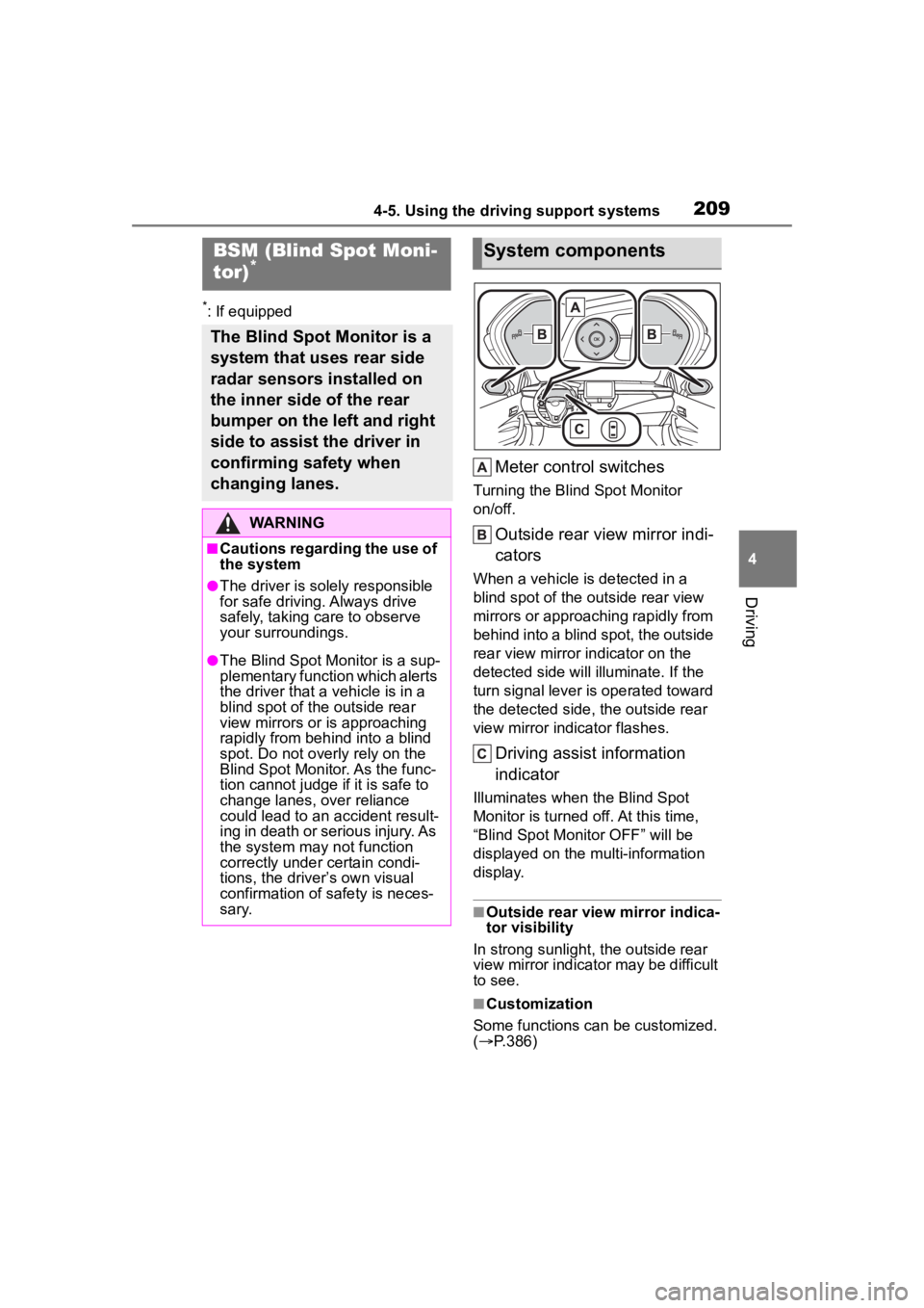
Meter control switches
Turning the Blind Spot Monitor
on/off.
Outside rear view mirror indi-
cators
When a vehicle is detected in a
blind spot of the outside rear view
mirrors or approaching rapidly from
behind into a blind spot, the outside
rear view mirror indicator on the
detected side will illuminate. If the
turn signal lever is operated toward
the detected side, the outside rear
view mirror indicator flashes.
Driving assist information
indicator
Illuminates when the Blind Spot
Monitor is turned off. At this time,
“Blind Spot Monitor OFF” will be
displayed on the multi-information
display.
■Outside rear view mirror indica-
tor visibility
In strong sunlight, the outside rear
view mirror indicator may be difficult
to see.
■Customization
Some functions can be customized.
( P.386)
BSM (Blind Spot Moni-
tor)*
The Blind Spot Monitor is a
system that uses rear side
radar sensors installed on
the inner side of the rear
bumper on the left and right
side to assist the driver in
confirming safety when
changing lanes.
WARNING
■Cautions regarding the use of
the system
●The driver is solely responsible
for safe driving. Always drive
safely, taking care to observe
your surroundings.
●The Blind Spot Monitor is a sup-
plementary function which alerts
the driver that a vehicle is in a
blind spot of the outside rear
view mirrors or is approaching
rapidly from behind into a blind
spot. Do not overly rely on the
Blind Spot Monitor. As the func-
tion cannot judge if it is safe to
change lanes, over reliance
could lead to an accident result-
ing in death or serious injury. As
the system may not function
correctly under certain condi-
tions, the driver’s own visual
confirmation of safety is neces-
sary.
System components
Page 210 of 436

2104-5. Using the driving support systems
The Blind Spot Monitor can be
enabled/disabled on
(4.2-inch display) or (7-inch
display) of the multi-information
display. (P.386)
When the Blind Spot Monitor
function is off, the driving assist
information indicator ( P.70)
will illuminate. At this time,
"Blind Spot Monitor OFF" will be
displayed on the multi-informa-
WARNING
■To ensure the system can
operate properly
Blind Spot Monitor sensors are
installed behind the left and right
sides of the rear bumper respec-
tively. Observe the following to
ensure the Blind Spot Monitor can
operate correctly.
●Keep the sensors and the sur-
rounding areas on the rear
bumper clean at all times.
If a sensor or its surrounding area
on the rear bumper is dirty or cov-
ered with snow, the Blind Spot
Monitor may not operate and a
warning message will be dis-
played. In this situation, clear off
the dirt or snow and drive the
vehicle with the operation condi-
tions of the BSM function
( P.212) satisfied for approxi-
mately 10 minutes. If the warning
message does not disappear,
have the vehicle inspected by
your Toyota dealer.
●Do not attach accessories,
stickers (including transparent
stickers), aluminum tape, etc. to
a sensor or its surrounding area
on the rear bumper.
●Do not subject a sensor or its
surrounding area on the rear
bumper to a strong impact.
If a sensor is moved even
slightly off position, the system
may malfunction and vehicles
may not be detected correctly.
In the following si tuations, have
your vehicle inspected by your
Toyota dealer.
• A sensor or its surrounding area is subject to a strong impact.
• If the surrounding area of a sen- sor is scratched or dented, or
part of them h as become dis-
connected.
●Do not disassemble the sensor.
●Do not modify the sensor or sur-
rounding area on the rear
bumper.
●If a sensor or the rear bumper
needs to be removed/installed
or replaced, contact your Toyota
dealer.
●Do not paint the rear bumper
any color other t han an official
Toyota color.
Turning the Blind Spot
Monitor on/off
Page 215 of 436
2154-5. Using the driving support systems
4
Driving
The RCTA can be enabled/dis-
abled on (4.2-inch display)
or (7-inch display) of the
multi-information display.
(P.386)
When the RCTA function is off,
the driving assist information
indicator ( P.70) will illuminate.
At this time, "Rear Cross Traffic Alert OFF" will be displayed on
the multi-information display.■Outside rear vie
w mirror indica-
tor visibility
In strong sunlight, the outside rear
view mirror indicator may be difficult
to see.
■Hearing the RCTA buzzer
The RCTA buzzer may be difficult to
hear over loud noises, such as if the
audio system volume is high.
■Rear side radar sensors
P.210
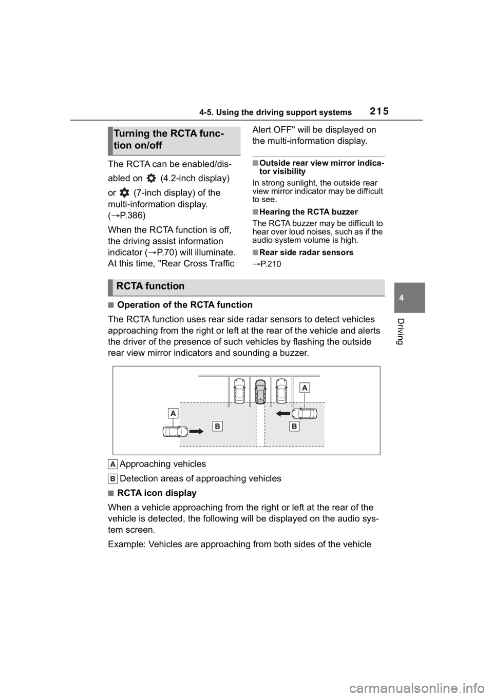
■Operation of the RCTA function
The RCTA function uses rear side radar sensors to detect vehicles
approaching from the right or left at the rear of the vehicle a nd alerts
the driver of the presence of such vehicles by flashing the out side
rear view mirror indicators and sounding a buzzer.
Approaching vehicles
Detection areas of approaching vehicles
■RCTA icon display
When a vehicle approaching from the right or left at the rear o f the
vehicle is detected, the following will be displayed on the audio sys-
tem screen.
Example: Vehicles are approaching from both sides of the vehicl e
Turning the RCTA func-
tion on/off
RCTA function
Page 220 of 436
2204-5. Using the driving support systems
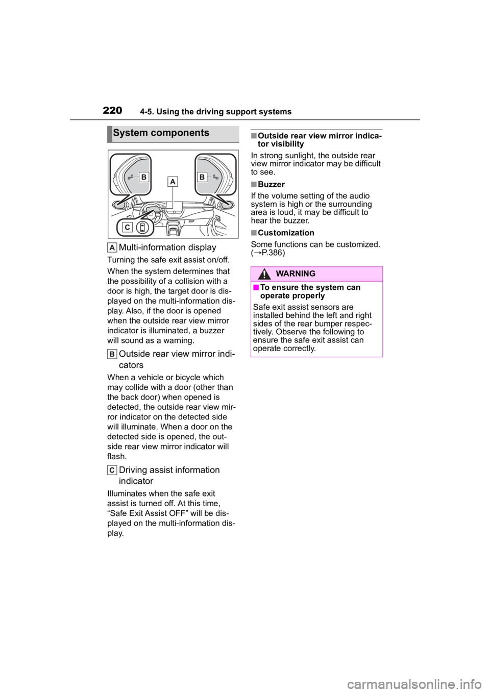
Multi-information display
Turning the safe exit assist on/off.
When the system determines that
the possibility of a collision with a
door is high, the target door is dis-
played on the multi-information dis-
play. Also, if the door is opened
when the outside rear view mirror
indicator is illuminated, a buzzer
will sound as a warning.
Outside rear view mirror indi-
cators
When a vehicle or bicycle which
may collide with a door (other than
the back door) when opened is
detected, the outsid e rear view mir-
ror indicator on t he detected side
will illuminate. When a door on the
detected side is opened, the out-
side rear view mirror indicator will
flash.
Driving assist information
indicator
Illuminates when the safe exit
assist is turned off. At this time,
“Safe Exit Assist OFF” will be dis-
played on the multi-information dis-
play.
■Outside rear vie w mirror indica-
tor visibility
In strong sunlight, the outside rear
view mirror indicator may be difficult
to see.
■Buzzer
If the volume setting of the audio
system is high or the surrounding
area is loud, it may be difficult to
hear the buzzer.
■Customization
Some functions can be customized.
( P.386)
System components
WARNING
■To ensure the system can
operate properly
Safe exit assist sensors are
installed behind the left and right
sides of the rear bumper respec-
tively. Observe the following to
ensure the safe e xit assist can
operate correctly.
Page 221 of 436
2214-5. Using the driving support systems
4
Driving
The safe exit assist can be
enabled/disabled on
(4.2-inch display) or (7-inch
display) of the multi-information
display. (P.386)
When the safe exit assist is off,
the driving assist information
indicator will illuminate. At this
time, “Safe Exit Assist OFF” will
be displayed on the multi-infor-
mation display. Each time the
engine switch is turned to ON,
the safe exit assist is enabled.
WARNING
●Keep the sensors and the sur-
rounding areas on the rear
bumper clean at all times.
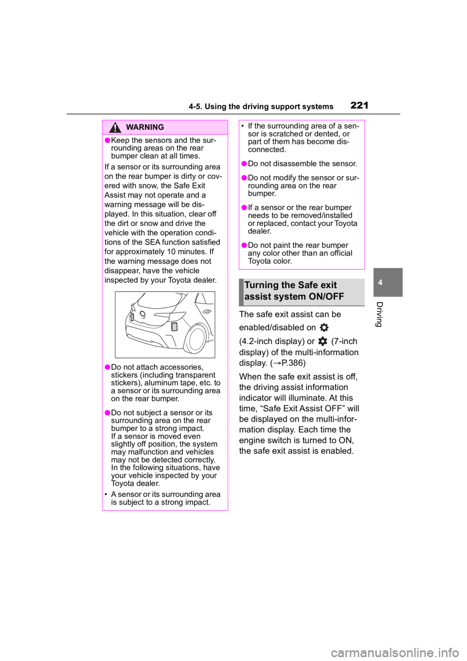
If a sensor or its surrounding area
on the rear bumper is dirty or cov-
ered with snow, the Safe Exit
Assist may not operate and a
warning message will be dis-
played. In this situation, clear off
the dirt or snow and drive the
vehicle with the operation condi-
tions of the SEA function satisfied
for approximately 10 minutes. If
the warning message does not
disappear, have the vehicle
inspected by your Toyota dealer.
●Do not attach accessories,
stickers (including transparent
stickers), aluminum tape, etc. to
a sensor or its surrounding area
on the rear bumper.
●Do not subject a sensor or its
surrounding area on the rear
bumper to a strong impact.
If a sensor is moved even
slightly off position, the system
may malfunction and vehicles
may not be detected correctly.
In the following si tuations, have
your vehicle inspected by your
Toyota dealer.
• A sensor or its surrounding area is subject to a strong impact.
• If the surrounding area of a sen- sor is scratched or dented, or
part of them h as become dis-
connected.
●Do not disassemble the sensor.
●Do not modify the sensor or sur-
rounding area on the rear
bumper.
●If a sensor or the rear bumper
needs to be removed/installed
or replaced, contact your Toyota
dealer.
●Do not paint the rear bumper
any color other t han an official
Toyota color.
Turning the Safe exit
assist system ON/OFF