transmission TOYOTA HIGHLANDER 2001 Service Service Manual
[x] Cancel search | Manufacturer: TOYOTA, Model Year: 2001, Model line: HIGHLANDER, Model: TOYOTA HIGHLANDER 2001Pages: 2572, PDF Size: 34.8 MB
Page 323 of 2572
2005 HIGHLANDER (EWD592U)
104
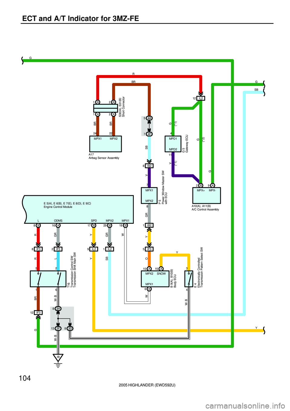
ECT and A/T Indicator for 3MZ-FE
BMPX-
A
1MPX1
W
2IF3R
SNOW MPX1
A 16
10
GR
ODMS9
MPX2
L
GR W- B
L
W- BW- BR
MPX2
V GR Y
E 4
29 BBR
R
8B
6
IB 13 3F6
83H3
4 A17
IF3 82B A IB2 8
IB2 1
IF3 5
15
O
7
8 MPX1
MPX2
A
P 5
MPX+
W
18 B
52
BR G
B
Y
SPD
17 B
IL2 9
Y
G
83D2 B 1
A 1A2
BR
24
MPX1
BR
22
MPX2
G V
4
11MPD1
MPD2
G 5
IL2 12
SB
74F 54AG
SB
Y IL2 1
SB
IF3 12
(
*1) (
*1)
G
(
*2)
G
Y
T16
S30(
A)
, S31(
B)
A10(
A)
, A11(
B)
B 9(
A)
, B10(
B)
E 5(
A)
, E 6(
B)
, E 7(
E)
, E 8(
D)
, E 9(
C)
A/C Control Assembly Airbag Sensor Assembly
Body ECU
Electronically Controlled
Transmission Pattern Select SW
Engine Control Module
Gateway ECU Power Window Master SW
with ECUShort Connector Transmission Control SW
Transmission Shift Main SW
Page 326 of 2572
2005 HIGHLANDER (EWD592U)
107
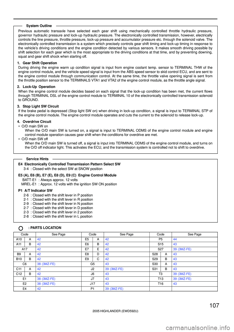
Previous automatic transaxle have selected each gear shift using mechanically controlled throttle hydraulic pressure,
governor hydraulic pressure and lock-up hydraulic pressure. The electronically controlled transmission, however, electrically
controls the line pressure, throttle pressure, lock-up pressure and accumulator pressure etc. through the solenoid valve. The
electronically controlled transmission is a system which precisely controls gear shift timing and lock-up timing in response to
the vehicle's driving conditions and the engine condition detected by various sensors. It makes smooth driving possible by
shift selection for each gear which is the most appropriate to the driving conditions at that time, and by preventing downing,
squat and gear shift shock when starting off.
1. Gear Shift Operation
During driving the engine warm up condition signal is input from engine coolant temp. sensor to TERMINAL THW of the
engine control module, and the vehicle speed signal is input from the ABS speed sensor to skid control ECU, and are sent to
the engine control module through communication control. At the same time, the throttle valve opening signal is sent from
the throttle position sensor to the TERMINALS VTA1 and VTA2 of the engine control module, as the throttle angle signal.
2. Lock-Up Operation
When the engine control module decides based on each signal that the lock-up condition has been met, the current flows
through TERMINAL DSL of the engine control module to TERMINAL 10 of the electronically controlled transmission solenoid
to GROUND.
3. Stop Light SW Circuit
If the brake pedal is depressed (Stop light SW on) when driving in lock-up condition, a signal is input to TERMINAL STP of
the engine control module. The engine control module operates and cuts the current to the solenoid to release lock-up.
4. Overdrive Circuit
*O/D main SW on
When the O/D main SW is turned on, a signal is input to TERMINAL ODMS of the engine control module and engine
control module operation causes gear shift when the conditions for overdrive are met.
*O/D main SW off
When the O/D main SW is turned off, a signal is input into TERMINAL ODMS of the engine control module, and turns on
the O/D off indicator light. This activates the ECU, and the transmission system is controlled not to shift to overdrive.
E4 Electronically Controlled Transmission Pattern Select SW
3-4 : Closed with the select SW at SNOW position
E5 (A), E6 (B), E7 (E), E8 (D), E9 (C) Engine Control Module
BATT-E1 : Always approx. 12 volts
MREL-E1 : Approx. 12 volts with the ignition SW ON position
P1 A/T Indicator SW
2-6 : Closed with the shift lever in P position
2-1 : Closed with the shift lever in R position
2-9 : Closed with the shift lever in N position
2-7 : Closed with the shift lever in D position
2-3 : Closed with the shift lever in 2 position
2-8 : Closed with the shift lever in L position
: PARTS LOCATION
CodeSee PageCodeSee PageCodeSee Page
A10A42E5A42P544
A11B42E6B42S1543
A1742E7E42S2739 (3MZ-FE)
B9A42E8D42S28A43
B10B42E9C42S29B43
C638 (3MZ-FE)G543S30A43
C11A42J239 (3MZ-FE)S31B43
C12B42J643T339 (3MZ-FE)
E138 (3MZ-FE)J743T1339 (3MZ-FE)
E238 (3MZ-FE)J1743T1643
E442P139 (3MZ-FE)
System Outline
Service Hints
Page 392 of 2572
'05 HIGHLANDER_U (L/O 0409)
232
2005 HIGHLANDER from Nov. '04 Prod. (OM48570U)
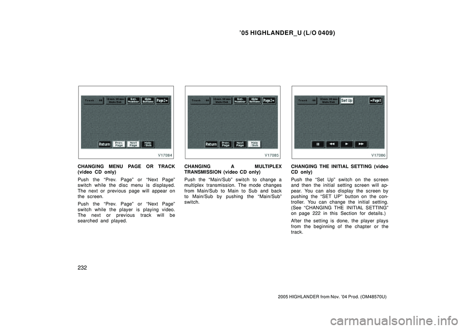
CHANGING MENU PAGE OR TRACK
(video CD only)
Push the Prev. Pageº or Next Pageº
switch while the disc menu is displayed.
The next or previous page will appear on
the screen.
Push the Prev. Pageº or Next Pageº
switch while the player is playing video.
The next or previous track will be
searched and played.CHANGING A MULTIPLEX
TRANSMISSION (video CD only)
Push the Main/Subº switch to change a
multiplex transmission. The mode changes
from Main/Sub to Main to Sub and back
to Main/Sub by pushing the Main/Subº
switch.CHANGING THE INITIAL SETTING (video
CD only)
Push the Set Upº switch on the screen
and then the initial setting screen will ap-
pear. You can also display the screen by
pushing the SET UPº button on the con-
troller. You can change the initial setting.
(See CHANGING THE INITIAL SETTINGº
on page 222 in this Section for details.)
After the setting is done, the player plays
from the beginning of the chapter or the
track.
Page 407 of 2572
2005 HIGHLANDER (EWD592U)
11 0
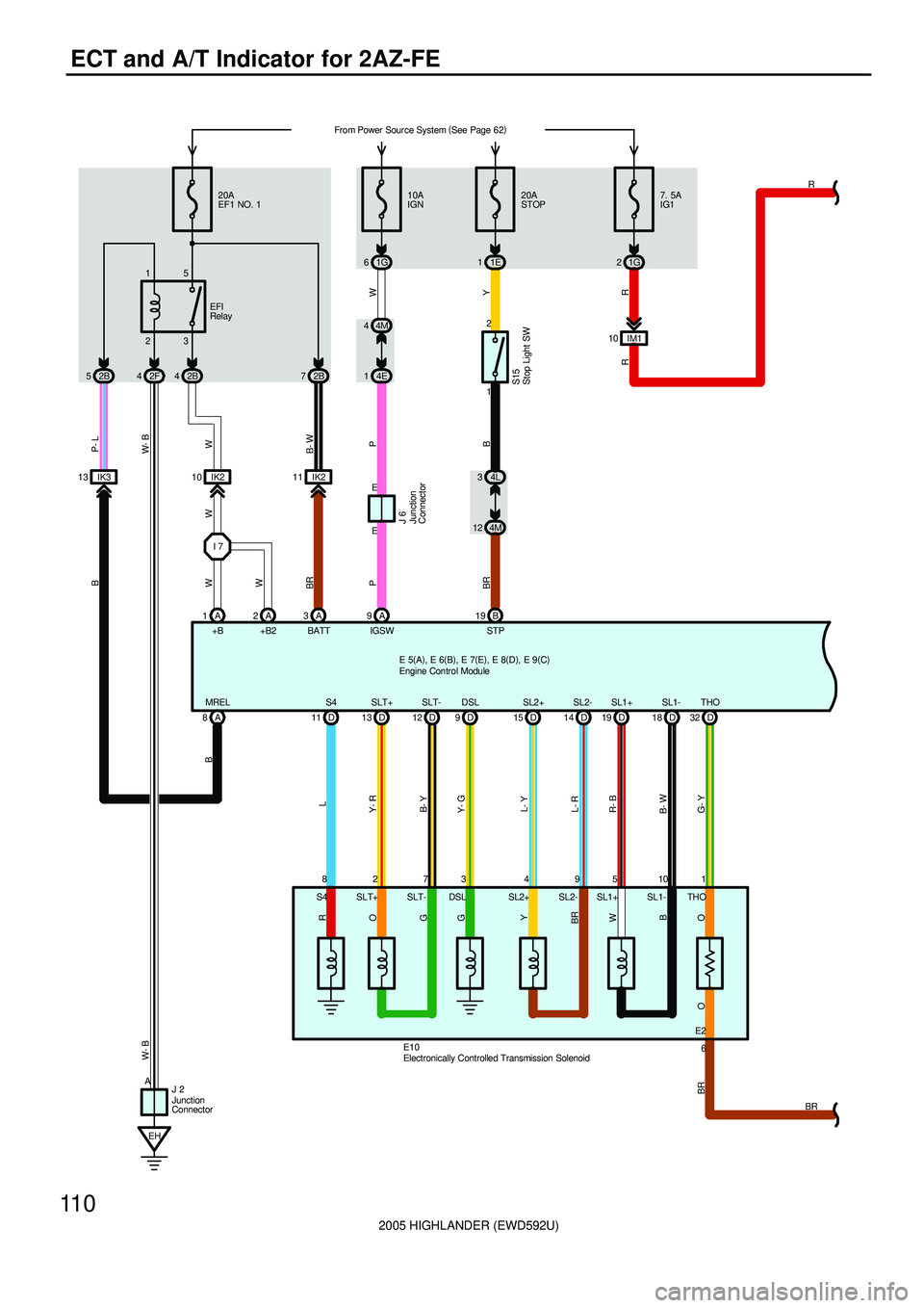
ECT and A/T Indicator for 2AZ-FE
1 9 4 3 7 2 8
G- YW P- L
+B BATT20A
EF1 NO. 1
B- W W- B
L
Y- R
B- Y
Y- G
L- Y
L- R
23 15
2B 4 2F 4 2B 52B7
Y
R W
IK2 10 IK21110A
IGN
1G 620A
STOP
1E 1
4E 1
B BRP
I 74M 4
EH1 2
4M 124L 3
1A A3A9B1921G7. 5A
IG1
A 8
BRW
D 11 D13 D9D15 D32 D 12 D14R
E10SL1- SL1+
18 D 19 D
B- WR- B
510 IGSW STP
A
J 2MREL S4 SLT+ SLT- DSL SL2+ SL2-
W- B
THO
S15
EFI
Relay
IK3 13
B
B
E2 IM1 10
R
E
E
R
O
G
G
Y
BR
O
+B2 2A
WW
P
W
B
O BR
BR 6 THO SL1- SL1+ SL2- SL2+ DSL SLT- SLT+ S4
J 6
From Power Source System (
See Page 62)
E 5(
A)
, E 6(
B)
, E 7(
E)
, E 8(
D)
, E 9(
C)
Engine Control Module
Electronically Controlled Transmission Solenoid
Junction
Connector
Junction
Connector
Stop Light SW
Page 409 of 2572
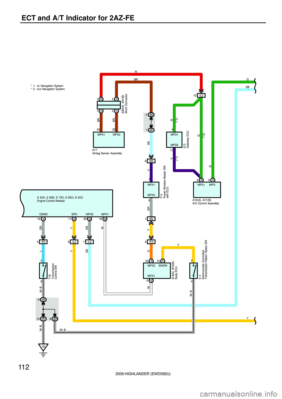
2005 HIGHLANDER (EWD592U)
11 2
ECT and A/T Indicator for 2AZ-FE
BMPX-
A
MPX1
W
2IF3R
SNOW MPX1
A 16
10
GR
ODMS9
MPX2
L
GR W- B
W- BW- B
MPX2
V GR Y
E 4
29 BBR
6
IB 13 3F6
83H3
4 A17
2B A IB2 8
IB2 1
IF3 5
15
O
7
8 MPX1
MPX2
A
P 5
MPX+
W
18 B
2B
Y
SPD
17 B
IL2 9
Y
83D2 B 1
A 1A2
BR
24
MPX1
BR
22
MPX2
G V
4
11MPD1
MPD2
G 5
IL2 12
SB
74F 54AG
Y IL2 1
SB
(
*1) (
*1)
G
(
*2)
G
Y
T16
* 1 : w/ Navigation System
* 2 : w/o Navigation SystemSB
W- B
S30(
A)
, S31(
B)
B 9(
A)
, B10(
B)
E 5(
A)
, E 6(
B)
, E 7(
E)
, E 8(
D)
, E 9(
C)
A10(
A)
, A11(
B)
A/C Control Assembly Air bag Sensor Assembly
Body ECU
Electronically Controlled
Transmission Pattern Select SW
Engine Contr ol Module
Gateway ECU Power Window Master SW
with ECUShort Connector Transmission
Control SW
Page 412 of 2572
2005 HIGHLANDER (EWD592U)
11 5
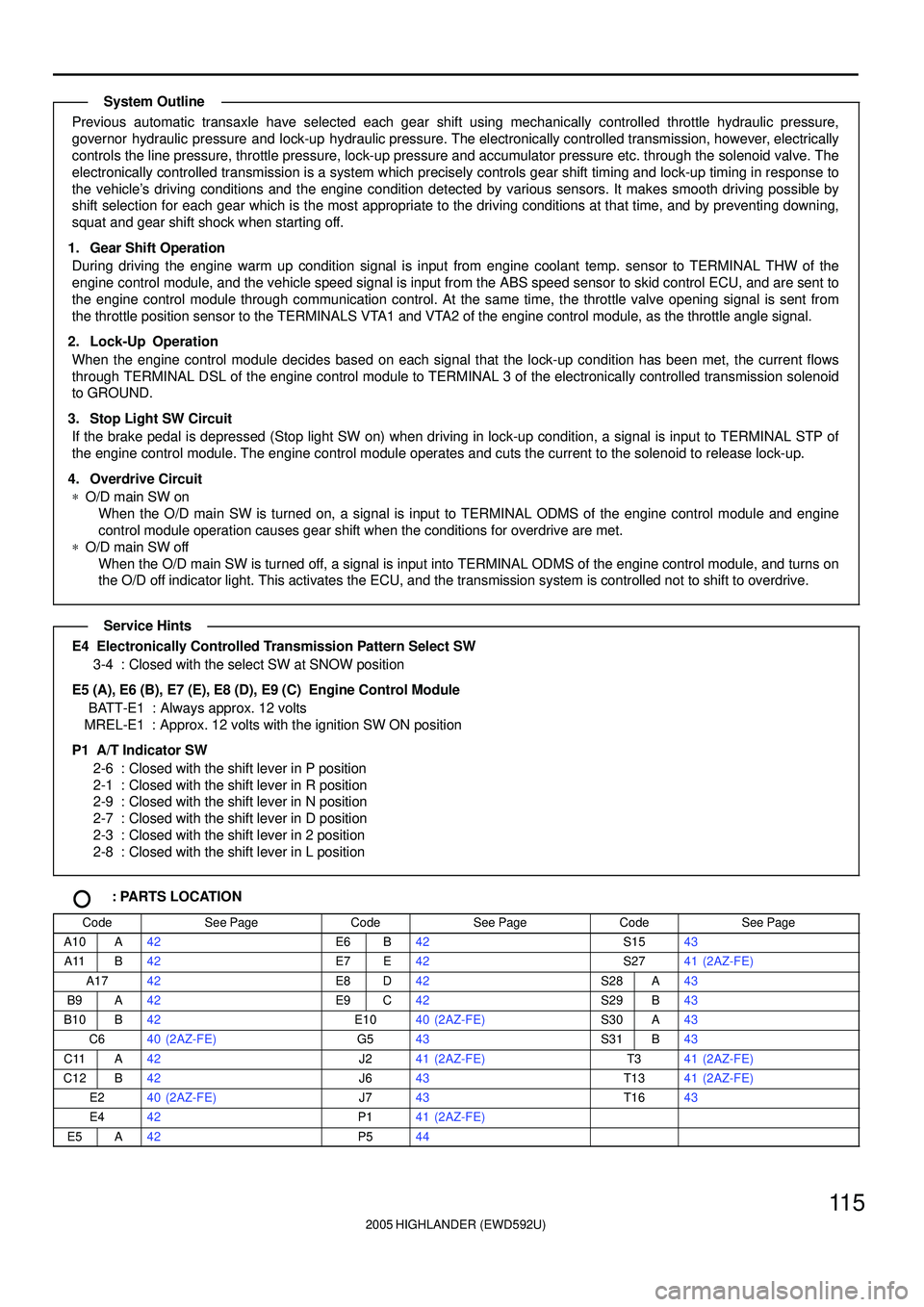
Previous automatic transaxle have selected each gear shift using mechanically controlled throttle hydraulic pressure,
governor hydraulic pressure and lock-up hydraulic pressure. The electronically controlled transmission, however, electrically
controls the line pressure, throttle pressure, lock-up pressure and accumulator pressure etc. through the solenoid valve. The
electronically controlled transmission is a system which precisely controls gear shift timing and lock-up timing in response to
the vehicle's driving conditions and the engine condition detected by various sensors. It makes smooth driving possible by
shift selection for each gear which is the most appropriate to the driving conditions at that time, and by preventing downing,
squat and gear shift shock when starting off.
1. Gear Shift Operation
During driving the engine warm up condition signal is input from engine coolant temp. sensor to TERMINAL THW of the
engine control module, and the vehicle speed signal is input from the ABS speed sensor to skid control ECU, and are sent to
the engine control module through communication control. At the same time, the throttle valve opening signal is sent from
the throttle position sensor to the TERMINALS VTA1 and VTA2 of the engine control module, as the throttle angle signal.
2. Lock-Up Operation
When the engine control module decides based on each signal that the lock-up condition has been met, the current flows
through TERMINAL DSL of the engine control module to TERMINAL 3 of the electronically controlled transmission solenoid
to GROUND.
3. Stop Light SW Circuit
If the brake pedal is depressed (Stop light SW on) when driving in lock-up condition, a signal is input to TERMINAL STP of
the engine control module. The engine control module operates and cuts the current to the solenoid to release lock-up.
4. Overdrive Circuit
*O/D main SW on
When the O/D main SW is turned on, a signal is input to TERMINAL ODMS of the engine control module and engine
control module operation causes gear shift when the conditions for overdrive are met.
*O/D main SW off
When the O/D main SW is turned off, a signal is input into TERMINAL ODMS of the engine control module, and turns on
the O/D off indicator light. This activates the ECU, and the transmission system is controlled not to shift to overdrive.
E4 Electronically Controlled Transmission Pattern Select SW
3-4 : Closed with the select SW at SNOW position
E5 (A), E6 (B), E7 (E), E8 (D), E9 (C) Engine Control Module
BATT-E1 : Always approx. 12 volts
MREL-E1 : Approx. 12 volts with the ignition SW ON position
P1 A/T Indicator SW
2-6 : Closed with the shift lever in P position
2-1 : Closed with the shift lever in R position
2-9 : Closed with the shift lever in N position
2-7 : Closed with the shift lever in D position
2-3 : Closed with the shift lever in 2 position
2-8 : Closed with the shift lever in L position
: PARTS LOCATION
CodeSee PageCodeSee PageCodeSee Page
A10A42E6B42S1543
A11B42E7E42S2741 (2AZ-FE)
A1742E8D42S28A43
B9A42E9C42S29B43
B10B42E1040 (2AZ-FE)S30A43
C640 (2AZ-FE)G543S31B43
C11A42J241 (2AZ-FE)T341 (2AZ-FE)
C12B42J643T1341 (2AZ-FE)
E240 (2AZ-FE)J743T1643
E442P141 (2AZ-FE)
E5A42P544
System Outline
Service Hints
Page 479 of 2572
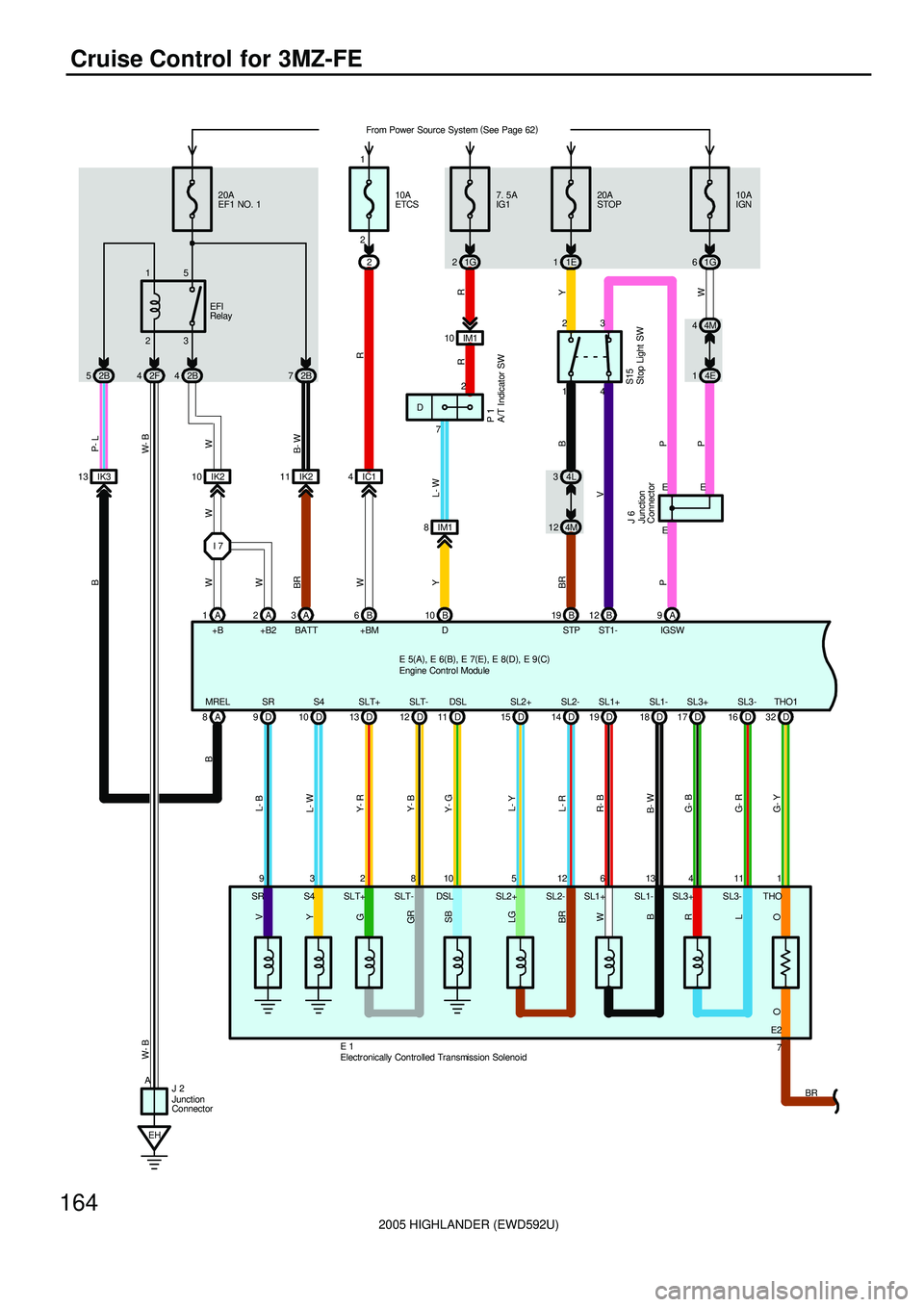
2005 HIGHLANDER (EWD592U)
164
Cruise Control for 3MZ-FE
1 11 4 12 5 10 8 2 3
G- YW P- L
+B BATT20A
EF1 NO. 1
B- W W- B
L- W
Y- R
Y- B
Y- G
L- Y
L- R
G- B
G- R
23 15
2B 4 2F 4 2B 52B7
Y
W
IK2 10 IK21110A
IGN
1G 6 20A
STOP
1E 1
4E 1
B BR
P
I 74M 4
EH1 2
4M 124L 3
1A A3A 9 B 19
A 8
BRW
D 10 D13 D11 D15 D17 D32 D 16 D 12 D14 9
L- B
E 1SL1- SL1+
18 D 19 D
B- WR- B
613IGSW STP
A
J 2MREL S4 SLT+ SLT- DSL SL2+ SL2-
W- B
SL3+ SL3- THO1
D
S15
EFI
Relay
IK3 13
B
B
9E
E
Y
G
GR
SB
LG
BR
R
OL
+B2 2A
WW
P W
B
SR
O
E
P V
B 12
ST1-4 3
R
10A
ETCS
2
W
B 6
+BMIC1 42 1
L- W
R
721G7. 5A
IG1
B 10
D 8IM1IM1 10
R Y
2
J 6P 1 V
THO SL3- SL3+ SL1- SL1+ SL2- SL2+ DSL SLT- SLT+ S4 SR
E2
7
BR D From Power Source System (
See Page 62)
E 5(
A)
, E 6(
B)
, E 7(
E)
, E 8(
D)
, E 9(
C)
Electr onically Controlled Transmission SolenoidEngine Control Module
Junction
Connector
Junction
ConnectorA/T Indicator SW
Stop Light SW
Page 487 of 2572
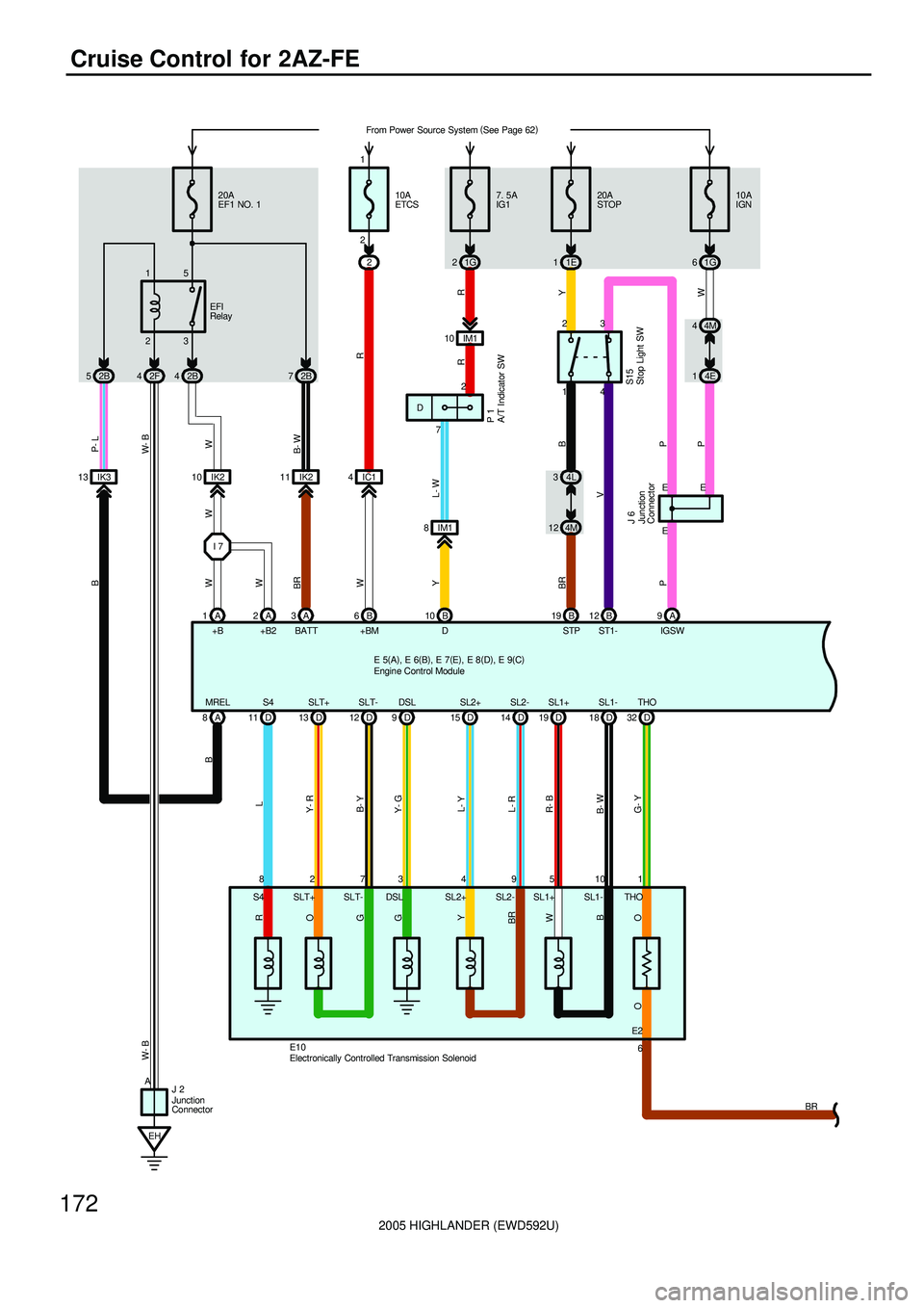
2005 HIGHLANDER (EWD592U)
172
Cruise Control for 2AZ-FE
1 9 4 3 7 2 8
G- YW P- L
+B BATT20A
EF1 NO. 1
B- W W- B
L
Y- R
B- Y
Y- G
L- Y
L- R
23 15
2B 4 2F 4 2B 52B7
Y
W
IK2 10 IK21110A
IGN
1G 6 20A
STOP
1E 1
4E 1
B BR
P
I 74M 4
EH1 2
4M 124L 3
1A A3A 9 B 19
A 8
BRW
D 11 D13 D9D15 D32 D 12 D14
E10SL1- SL1+
18 D 19 D
B- WR- B
510IGSW STP
A
J 2MREL S4 SLT+ SLT- DSL SL2+ SL2-
W- B
THO
S15
EFI
Relay
IK3 13
B
B
E
E
R
O
G
G
Y
BR
O
+B2 2A
WW
P W
B
O
E
P V
B 12
ST1-4 3
R
10A
ETCS
2
W
B 6
+BMIC1 42 1
L- W
R
21G7. 5A
IG1
B 10
D 8IM1IM1 10
R Y
2
J 6P 1
BR THO SL1- SL1+ SL2- SL2+ DSL SLT- SLT+ S4
6 E2 7 D From Power Source System (
See Page 62)
E 5(
A)
, E 6(
B)
, E 7(
E)
, E 8(
D)
, E 9(
C)
Engine Control Module
Electronically Controlled Transmission Solenoid
Junction
Connector
Junction
ConnectorA/T Indicator SW
Stop Light SW
Page 499 of 2572
2005 HIGHLANDER (EWD592U)
184
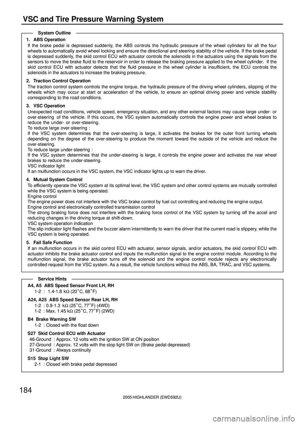
VSC and Tire Pressure Warning System
1. ABS Operation
If the brake pedal is depressed suddenly, the ABS controls the hydraulic pressure of the wheel cylinders for all the four
wheels to automatically avoid wheel locking and ensure the directional and steering stability of the vehicle. If the brake pedal
is depressed suddenly, the skid control ECU with actuator controls the solenoids in the actuators using the signals from the
sensors to move the brake fluid to the reservoir in order to release the braking pressure applied to the wheel cylinder. If the
skid control ECU with actuator detects that the fluid pressure in the wheel cylinder is insufficient, the ECU controls the
solenoids in the actuators to increase the braking pressure.
2. Traction Control Operation
The traction control system controls the engine torque, the hydraulic pressure of the driving wheel cylinders, slipping of the
wheels which may occur at start or acceleration of the vehicle, to ensure an optimal driving power and vehicle stability
corresponding to the road conditions.
3. VSC Operation
Unexpected road conditions, vehicle speed, emergency situation, and any other external factors may cause large under- or
over-steering of the vehicle. If this occurs, the VSC system automatically controls the engine power and wheel brakes to
reduce the under- or over-steering.
To reduce large over-steering :
If the VSC system determines that the over-steering is large, it activates the brakes for the outer front turning wheels
depending on the degree of the over-steering to produce the moment toward the outside of the vehicle and reduce the
over-steering.
To reduce large under-steering :
If the VSC system determines that the under-steering is large, it controls the engine power and activates the rear wheel
brakes to reduce the under-steering.
VSC indicator light
If an mulfunction occurs in the VSC system, the VSC indicator lights up to warn the driver.
4. Mutual System Control
To efficiently operate the VSC system at its optimal level, the VSC system and other control systems are mutually controlled
while the VSC system is being operated.
Engine control
The engine power does not interfere with the VSC brake control by fuel cut controlling and reducing the engine output.
Engine control and electronically controlled transmission control
The strong braking force does not interfere with the braking force control of the VSC system by turning off the accel and
reducing changes in the driving torque at shift-down.
VSC system operation indication
The slip indicator light flashes and the buzzer alarm intermittently to warn the driver that the current road is slippery, while the
VSC system is being operated.
5. Fail Safe Function
If an mulfunction occurs in the skid control ECU with actuator, sensor signals, and/or actuators, the skid control ECU with
actuator inhibits the brake actuator control and inputs the mulfunction signal to the engine control module. According to the
mulfunction signal, the brake actuator turns off the solenoid and the engine control module rejects any electronically
controlled request from the VSC system. As a result, the vehicle functions without the ABS, BA, TRAC, and VSC systems.
A4, A5 ABS Speed Sensor Front LH, RH
1-2 : 1.4-1.8 kW (20°C, 68°F)
A24, A25 ABS Speed Sensor Rear LH, RH
1-2 : 0.9-1.3 kW (25°C, 77°F) (4WD)
1-2 : Max. 1.45 kW (25°C, 77°F) (2WD)
B4 Brake Warning SW
1-2 : Closed with the float down
S27 Skid Control ECU with Actuator
46-Ground : Approx. 12 volts with the ignition SW at ON position
27-Ground : Approx. 12 volts with the stop light SW on (Brake pedal depressed)
31-Ground : Always continuity
S15 Stop Light SW
2-1 : Closed with brake pedal depressed
System Outline
Service Hints
Page 575 of 2572
1 Reset the oil replacement reminder (“MAINT REQD”) light after replacing engine oil, if vehicle is equipped with this light.2 Perform these service items only if you drive primarily under the conditions indicated.3 Required under the terms of the Emission Control Warranty.4 Inspec tthickness measurement and disc runout.5 Ex cept front differential of Corolla Matrix 4WD with manual transmission.6 See page 37 for details.7 Applies t o Coroll a M atrix 4WD and Sienna 4WD.8 Applies to Corolla Matrix 4WD, MR2 Spyder and Sienna 4WD.
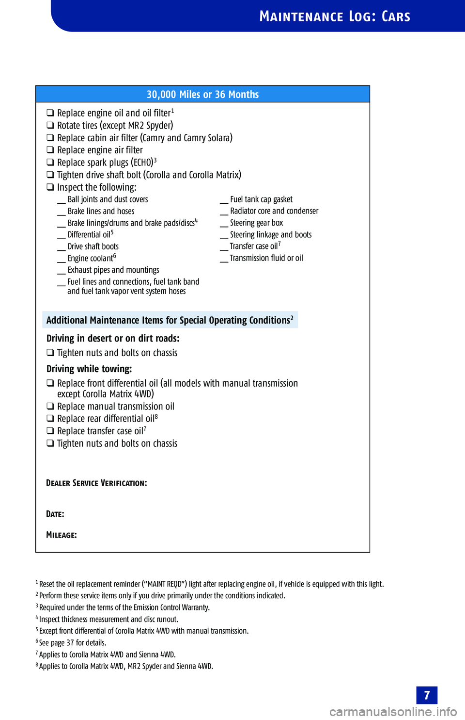
Maintenance Log: Cars
30,000 Miles or 36 Months
qReplace engine oil and oil filter1
qRotate tires (except MR2 Spyder)
qReplace cabin air filter (Camry and Camry Solara)
qReplace engine air filter
qReplace spark plugs (ECHO)3
qTighten drive shaft bolt (Corolla and Corolla Matrix)
qInspect the following:__ Ball joints and dust covers
__ Brake lines and hoses
__ Brake linings/drums and brake pads/discs
4
__ Differential oil5
__ Drive shaft boots
__ Engine coolant6
__ Exhaust pipes and mountings
__ Fuel lines and connections, fuel tank band
and fuel tank vapor vent system hoses
Additional Maintenance Items for Special Operating Conditions2
Driving in desert or on dirt roads:
qTighten nuts and bolts on chassis
Driving while towing:
qR epl ac e f ront diff erential oil (all models with manual transmission
e x ce pt Cor oll a M atrix 4WD)
qReplace manual transmission oil
qRepl ac e r ear differential oil8
qRepl ac e t ran sfer case oil7
qTighten nuts and bolts on chassis
Dealer Service Verification:
Date:
M ileage:
7
__ Fuel tank cap gasket
__ Radiator core and condenser
__ Steering gear box
__ Steering linkage and boots
__ Transfer case oil
7
__ Transmission fluid or oil