fuse box location TOYOTA HIGHLANDER 2001 Service Repair Manual
[x] Cancel search | Manufacturer: TOYOTA, Model Year: 2001, Model line: HIGHLANDER, Model: TOYOTA HIGHLANDER 2001Pages: 2572, PDF Size: 34.8 MB
Page 536 of 2572

2005 HIGHLANDER (EWD592U)
221
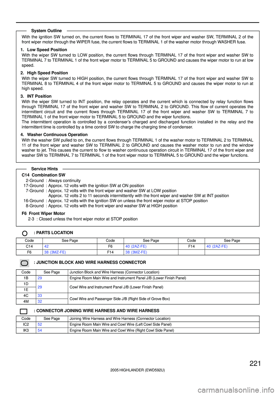
With the ignition SW turned on, the current flows to TERMINAL 17 of the front wiper and washer SW, TERMINAL 2 of the
front wiper motor through the WIPER fuse, the current flows to TERMINAL 1 of the washer motor through WASHER fuse.
1. Low Speed Position
With the wiper SW turned to LOW position, the current flows through TERMINAL 17 of the front wiper and washer SW to
TERMINAL 7 to TERMINAL 1 of the front wiper motor to TERMINAL 5 to GROUND and causes the wiper motor to run at low
speed.
2. High Speed Position
With the wiper SW turned to HIGH position, the current flows through TERMINAL 17 of the front wiper and washer SW to
TERMINAL 8 to TERMINAL 4 of the front wiper motor to TERMINAL 5 to GROUND and causes the wiper motor to run at
high speed.
3. INT Position
With the wiper SW turned to INT position, the relay operates and the current which is connected by relay function flows
through TERMINAL 17 of the front wiper and washer SW to TERMINAL 2 to GROUND. This flow of current operates the
intermittent circuit and the current flows through TERMINAL 17 of the front wiper and washer SW to TERMINAL 7 to
TERMINAL 1 of the front wiper motor to TERMINAL 5 to GROUND and the wiper functions.
The intermittent operation is controlled by a condenser's charged and discharged function installed in the relay and the
intermittent time is controlled by a time control SW to charge the charging time of condenser.
4. Washer Continuous Operation
With the washer SW pulled to on, the current flows through TERMINAL 1 of the washer motor to TERMINAL 2 to TERMINAL
11 of the front wiper and washer SW to TERMINAL 2 to GROUND and causes the washer motor to run and the window
washer to jet. This causes the current to flow to washer continuous operation circuit in TERMINAL 17 of the front wiper and
washer SW to TERMINAL 7 to TERMINAL 1 of the front wiper motor to TERMINAL 5 to GROUND and the wiper functions.
C14 Combination SW
2-Ground : Always continuity
17-Ground : Approx. 12 volts with the ignition SW at ON position
7-Ground : Approx. 12 volts with the front wiper and washer SW at LOW position
Approx. 12 volts 2 to 11 seconds intermittently with the front wiper and washer SW at INT position
16-Ground : Approx. 12 volts with the ignition SW on unless the front wiper motor at STOP position
8-Ground : Approx. 12 volts with the front wiper and washer SW at HIGH position
F6 Front Wiper Motor
2-3 : Closed unless the front wiper motor at STOP position
: PARTS LOCATION
CodeSee PageCodeSee PageCodeSee Page
C1442F640 (2AZ-FE)F1440 (2AZ-FE)
F638 (3MZ-FE)F1438 (3MZ-FE)
������ ���: JUNCTION BLOCK AND WIRE HARNESS CONNECTOR
CodeSee PageJunction Block and Wire Harness (Connector Location)
1B29Engine Room Main Wire and Instrument Panel J/B (Lower Finish Panel)
1D29Cowl Wire and Instrument Panel J/B (Lower Finish Panel)1E29Cowl Wire and Instrument Panel J/B (Lower Finish Panel)
4C33Cowl Wire and Passenger Side J/B (Right Side of Grove Box)4M32Cowl Wire and Passenger Side J/B (Right Side of Grove Box)
: CONNECTOR JOINING WIRE HARNESS AND WIRE HARNESS
CodeSee PageJoining Wire Harness and Wire Harness (Connector Location)
IC252Engine Room Main Wire and Cowl Wire (Left Cowl Side Panel)
IK354Engine Room Main Wire and Cowl Wire (Right Cowl Side Panel)
System Outline
Service Hints
Page 548 of 2572

2005 HIGHLANDER (EWD592U)
233
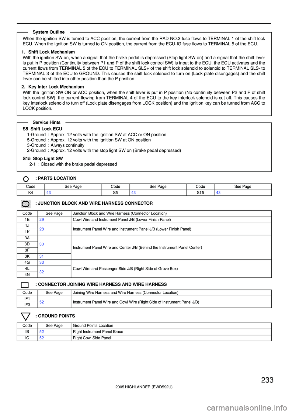
When the ignition SW is turned to ACC position, the current from the RAD NO.2 fuse flows to TERMINAL 1 of the shift lock
ECU. When the ignition SW is turned to ON position, the current from the ECU-IG fuse flows to TERMINAL 5 of the ECU.
1. Shift Lock Mechanism
With the ignition SW on, when a signal that the brake pedal is depressed (Stop light SW on) and a signal that the shift lever
is put in P position (Continuity between P1 and P of the shift lock control SW) is input to the ECU, the ECU activates and the
current flows from TERMINAL 5 of the ECU to TERMINAL SLS+ of the shift lock solenoid to solenoid to TERMINAL SLS- to
TERMINAL 3 of the ECU to GROUND. This causes the shift lock solenoid to turn on (Lock plate disengages) and the shift
lever can be shifted into other position than the P position
2. Key Inter Lock Mechanism
With the ignition SW ON or ACC position, when the shift lever is put in P position (No continuity between P2 and P of shift
lock control SW), the current flowing from TERMINAL 4 of the ECU to the key interlock solenoid is cut off. This causes the
key interlock solenoid to turn off (Lock plate disengages from LOCK position) and the ignition key can be turned from ACC to
LOCK position.
S5 Shift Lock ECU
1-Ground : Approx. 12 volts with the ignition SW at ACC or ON position
5-Ground : Approx. 12 volts with the ignition SW at ON position
3-Ground : Always continuity
2-Ground : Approx. 12 volts with the stop light SW on (Brake pedal depressed)
S15 Stop Light SW
2-1 : Closed with the brake pedal depressed
: PARTS LOCATION
CodeSee PageCodeSee PageCodeSee Page
K443S543S1543
������ ���: JUNCTION BLOCK AND WIRE HARNESS CONNECTOR
CodeSee PageJunction Block and Wire Harness (Connector Location)
1E29Cowl Wire and Instrument Panel J/B (Lower Finish Panel)
1J28Instrument Panel Wire and Instrument Panel J/B (Lower Finish Panel)1K28Instrument Panel Wire and Instrument Panel J/B (Lower Finish Panel)
3A
3D30Instrument Panel Wire and Center J/B (Behind the Instrument Panel Center)3FInstrument Panel Wire and Center J/B (Behind the Instrument Panel Center)
3K31
4G33
4L32Cowl Wire and Passenger Side J/B (Right Side of Grove Box)
4N32g(g )
: CONNECTOR JOINING WIRE HARNESS AND WIRE HARNESS
CodeSee PageJoining Wire Harness and Wire Harness (Connector Location)
IF152Instrument Panel Wire and Cowl Wire (Right Side of Instrument Panel J/B)IF352Instrument Panel Wire and Cowl Wire (Right Side of Instrument Panel J/B)
: GROUND POINTS
CodeSee PageGround Points Location
IB52Right Instrument Panel Brace
IC52Right Cowl Side Panel
System Outline
Service Hints
Page 700 of 2572

'05 HIGHLANDER_U (L/O 0409)
398
2005 HIGHLANDER from Nov. '04 Prod. (OM48570U)
Good Blown
Ty p e A
Good Blown
Ty p e B
Good Blown
Ty p e C
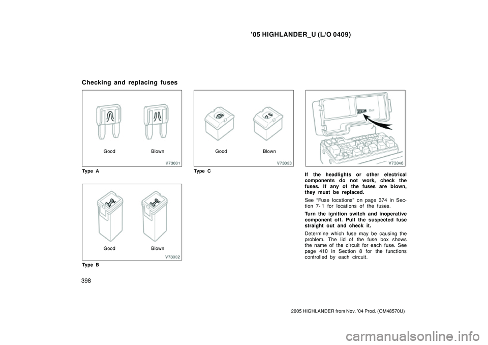
If the headlights or other electrical
components do not work, check the
fuses. If any of the fuses are blown,
they must be replaced.
See Fuse locationsº on page 374 in Sec-
tion 7- 1 for locations of the fuses.
Turn the ignition switch and inoperative
component off. Pull the suspected fuse
straight out and check it.
Determine which fuse may be causing the
problem. The lid of the fuse box shows
the name of the circuit for each fuse. See
page 410 in Section 8 for the functions
controlled by each circuit.
Checking and replacing fuses
Page 701 of 2572

'05 HIGHLANDER_U (L/O 0409)
399
2005 HIGHLANDER from Nov. '04 Prod. (OM48570U)
Type A fuses can be pulled out by using
the pull- out tool. The location of the pull-
out tool is shown in the illustration.
If you are not sure whether the fuse has
blown, try replacing the suspected fuse
with one that you know is good.
If the fuse has blown, push a new fuse
into the clip.
Only install a fuse with the amperage rat-
ing designated on the fuse box lid.
If you do not have a spare fuse, in an
emergency you can pull out the FR DEFº
or CIGº fuse, which may be dispensable
for normal driving, and use it if its amper-
age rating is the same.
If you cannot use one of the same amper-
age, use one that is lower, but as close
to the rating as possible. If the amperage
is lower than that specified, the fuse
might blow out again but this does not
indicate anything wrong. Be sure to get
the correct fuse as soon as possible and
return the substitute to its original clip.
It is a good idea to purchase a set of
spare fuses and keep them in your ve-
hicle for emergencies.If the new fuse immediately blows out,
there is a problem with the electrical sys-
tem. Have your Toyota dealer correct it as
soon as possible.
You should normalize the moon roof if it
does not operate automatically or the jam
protection function does not operate cor-
rectly after replacing blown fuses. To
normalize the moon roof, see Electric
moon roofº on page 36 in Section 1- 2.
CAUTION
Never use a fuse with a higher am-
perage rating, or any other object, in
place of a fuse. This may cause ex-
tensive damage and possibly a fire.
If any washer does not work or the low
windshield washer fluid level warning
light comes on, the washer tank may be
empty. Add washer fluid.
You may use plain water as washer fluid.
However, in cold areas where tempera-
tures range below the freezing point, use
washer fluid containing antifreeze. This
product is available at your Toyota dealer
and most auto parts stores. Follow the
manufacturer 's directions for how much to
mix with water.
Adding washer fluid