width TOYOTA HIGHLANDER 2018 Owners Manual (in English)
[x] Cancel search | Manufacturer: TOYOTA, Model Year: 2018, Model line: HIGHLANDER, Model: TOYOTA HIGHLANDER 2018Pages: 732, PDF Size: 14.5 MB
Page 198 of 732
1984-1. Before driving
HIGHLANDER_U (OM0E031U)
WARNING
■Capacity and distribution
●Do not exceed the maximum axle weight rating or the total vehicle
weight rating.
●Even if the total load of occupant’s weight and the cargo load is less
than the total load capacity, d o not apply the load unevenly. I mproper
loading may cause deterioration of steering or braking control which
may cause death or serious injury.
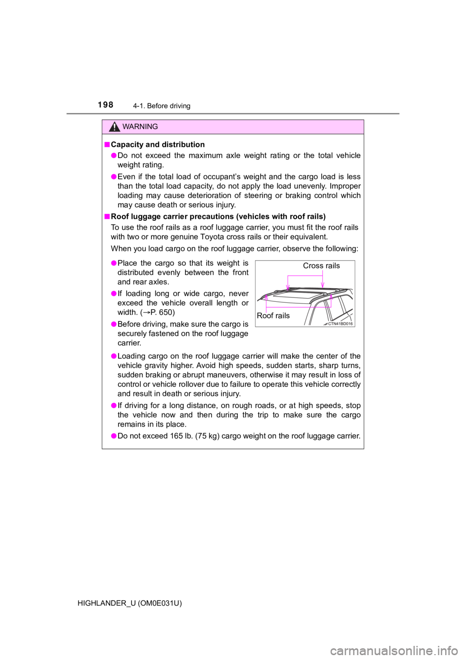
■Roof luggage carrier precautions (vehicles with roof rails)
To use the roof rails as a roof luggage carrier, you must fit t he roof rails
with two or more genuine Toyota cross rails or their equivalent.
When you load cargo on the roof luggage carrier, observe the fo llowing:
●Loading cargo on the roof luggage carrier will make the center of the
vehicle gravity higher. Avoid hi gh speeds, sudden starts, sharp turns,
sudden braking or abrupt maneuvers, otherwise it may result in loss of
control or vehicle rollover due to failure to operate this vehi cle correctly
and result in death or serious injury.
●If driving for a long distance, on rough roads, or at high spee ds, stop
the vehicle now and then during the trip to make sure the cargo
remains in its place.
●Do not exceed 165 lb. (75 kg) cargo weight on the roof luggage carrier.
●Place the cargo so that its weight is
distributed evenly between the front
and rear axles.
●If loading long or wide cargo, never
exceed the vehicle overall length or
width. (P. 650)
●Before driving, make sure the cargo is
securely fastened on the roof luggage
carrier.
Cross rails
Roof rails
Page 281 of 732
2814-5. Using the driving support systems
4
Driving
HIGHLANDER_U (OM0E031U)
■Operation conditions of each function
●Lane departure alert function
This function operates when all of the following conditions are met.
• LDA is turned on.
• Vehicle speed is approximately 32 mph (50 km/h) or more.
• System recognizes white (yellow) lines.
• Width of traffic lane is approximately 9.8 ft. (3 m) or more.
• Turn signal lever is not operated.
• Vehicle is driven on a straight road or around a gentle curve with a radius
of more than approximately 492 ft. (150 m).
• No system malfunctions are detected. ( P. 581)
● Steering control function
This function operates when all of the following conditions are met in addi-
tion to the operation conditions for the lane departure alert function.
• Setting for “Steering Assist” on of the multi-information display is set to “On”. ( P. 99)
• Vehicle is not accelerated or decelerated by a fixed amount or more.
• Steering wheel is not operated with a steering force level suitable for changing lanes.
• ABS, VSC, TRAC and PCS (Pre-Collision System) are not operatin g.
• TRAC or VSC is not turned off.
● Vehicle sway warning function
This function operates when all of the following conditions are met.
• Setting for “Sway Warning” on of the multi-information display is set to “On”.( P. 99)
• Vehicle speed is approximately 32 mph (50 km/h) or more.
• Width of traffic lane is approximately 9.8 ft. (3 m) or more.
• No system malfunctions are detected. ( P. 581)
Page 308 of 732
3084-5. Using the driving support systems
HIGHLANDER_U (OM0E031U)■
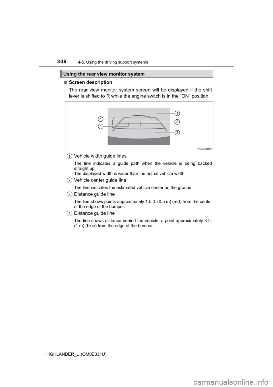
Screen description
The rear view monito
r system screen will be displayed if the sh ift
lever is shifted to R while the engine switch is in the “ON” po sition.
Vehicle width guide lines
The line indicates a guide path when the vehicle is being backe d
straight up.
The displayed width is wider than the actual vehicle width.
Vehicle center guide line
The line indicates the estimated vehicle center on the ground.
Distance guide line
The line shows points approximately 1.5 ft. (0.5 m) (red) from the center
of the edge of the bumper.
Distance guide line
The line shows distance behind the vehicle, a point approximate ly 3 ft.
(1 m) (blue) from the edge of the bumper.
Using the rear view monitor system
1
2
3
4
Page 310 of 732
3104-5. Using the driving support systems
HIGHLANDER_U (OM0E031U)■
Differences between the scr
een and the actual road
The distance guide lines and the vehicle width guide lines may not
actually be parallel with the div iding lines of the parking space, even
when they appear to be so. Be sure to check visually.
The distances between the vehicle width guide lines and the lef t
and right dividing lines of the parking space may not be equal, even
when they appear to be so. Be sure to check visually.
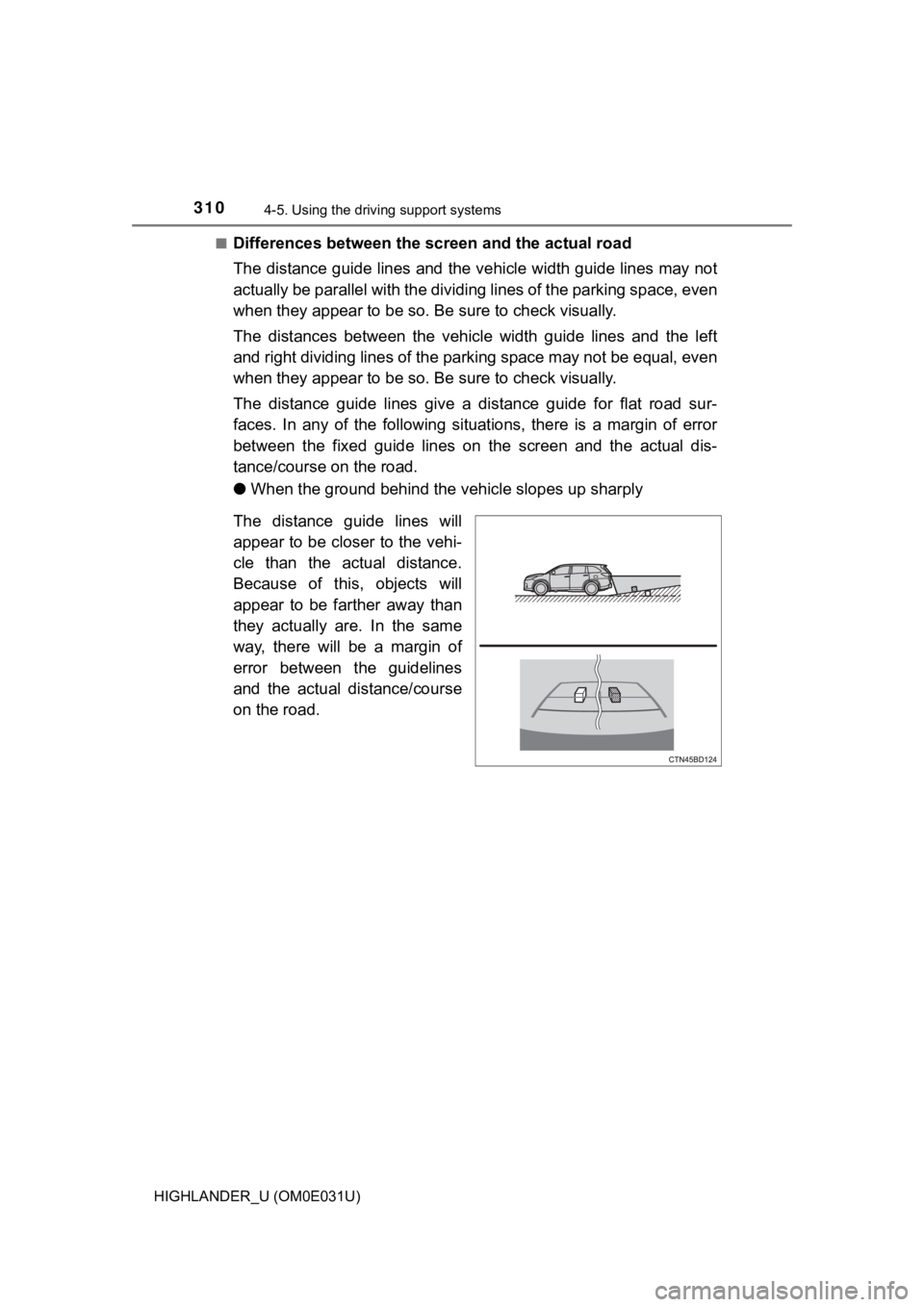
The distance guide lines give a distance guide for flat road sur-
faces. In any of the following situations, there is a margin of error
between the fixed guide lines on the screen and the actual dis-
tance/course on the road.
● When the ground behind the vehicle slopes up sharply
The distance guide lines will
appear to be closer to the vehi-
cle than the actual distance.
Because of this, objects will
appear to be farther away than
they actually are. In the same
way, there will be a margin of
error between the guidelines
and the actual distance/course
on the road.
Page 312 of 732
3124-5. Using the driving support systems
HIGHLANDER_U (OM0E031U)
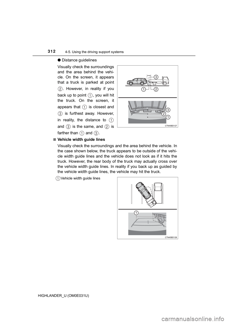
●Distance guidelines
Visually check the surroundings
and the area behind the vehi-
cle. On the screen, it appears
that a truck is parked at point . However, in reality if you
back up to point , you will hit
the truck. On the screen, it
appears that is closest and is furthest away. However,
in reality, the distance to
and is the same, and is
farther than and .
■Vehicle width guide lines
Visually check the surroundings and the area behind the vehicle. In
the case shown below, the truck appears to be outside of the ve hi-
cle width guide lines and the vehicle does not look as if it hi ts the
truck. However, the rear body of the truck may actually cross over
the vehicle width guide lines. In reality if you back up as gui ded by
the vehicle width guide lines, the vehicle may hit the truck.
Vehicle width guide lines
2
1
1
3
1
32
13
1
Page 341 of 732
3414-6. Driving tips
4
Driving
HIGHLANDER_U (OM0E031U)
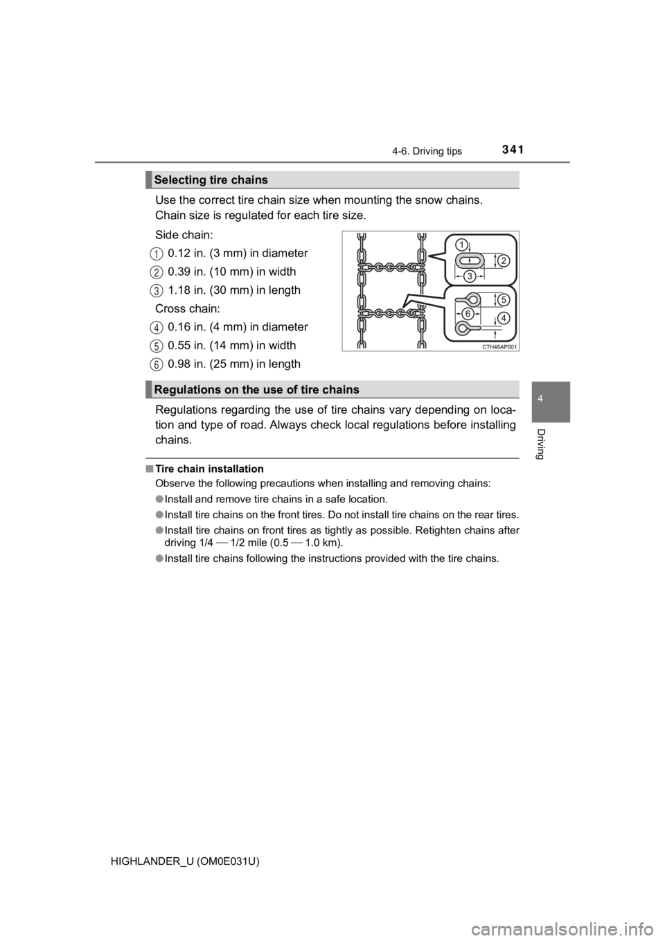
Use the correct tire chain size when mounting the snow chains.
Chain size is regulate d for each tire size.
Side chain: 0.12 in. (3 mm) in diameter
0.39 in. (10 mm) in width
1.18 in. (30 mm) in length
Cross chain: 0.16 in. (4 mm) in diameter
0.55 in. (14 mm) in width
0.98 in. (25 mm) in length
Regulations regarding the use of tire chains vary depending on loca-
tion and type of road. Always chec k local regulations before installing
chains.
■ Tire chain installation
Observe the following precautions when installing and removing chains:
● Install and remove tire chains in a safe location.
● Install tire chains on the front tires. Do not install tire chains on the rear tires.
● Install tire chains on front tires as tightly as possible. Reti ghten chains after
driving 1/4 1/2 mile (0.5 1.0 km).
● Install tire chains following the instructions provided with th e tire chains.
Selecting tire chains
1
2
3
4
5
6
Regulations on the use of tire chains
Page 650 of 732
650
HIGHLANDER_U (OM0E031U)
9-1. Specifications
*1: Unladen vehicles
*2: The model code is indicated on the Certification Label. (P. 651)
*3: With a seating capacity of 7 occupants
*4: With a seating capacity of 8 occupants
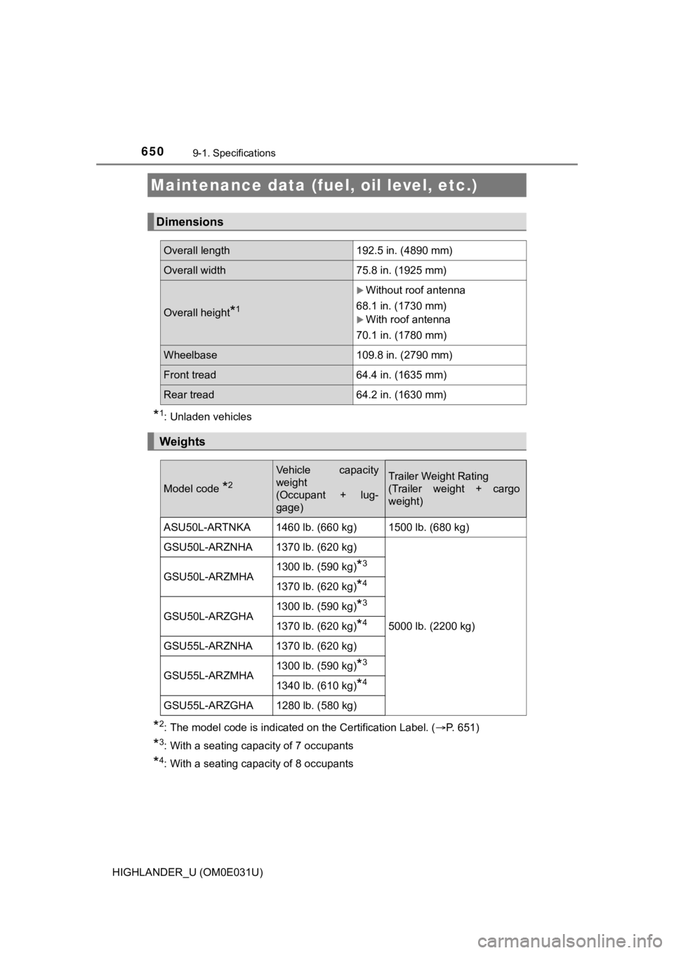
Maintenance data (fuel, oil level, etc.)
Dimensions
Overall length192.5 in. (4890 mm)
Overall width 75.8 in. (1925 mm)
Overall height*1
Without roof antenna
68.1 in. (1730 mm)
With roof antenna
70.1 in. (1780 mm)
Wheelbase 109.8 in. (2790 mm)
Front tread64.4 in. (1635 mm)
Rear tread 64.2 in. (1630 mm)
Weights
Model code *2
Vehicle capacity
weight
(Occupant + lug-
gage)Trailer Weight Rating
(Trailer weight + cargo
weight)
ASU50L-ARTNKA 1460 lb. (660 kg) 1500 lb. (680 kg)
GSU50L-ARZNHA 1370 lb. (620 kg)
5000 lb. (2200 kg)
GSU50L-ARZMHA
1300 lb. (590 kg)
*3
1370 lb. (620 kg)*4
GSU50L-ARZGHA
1300 lb. (590 kg)*3
1370 lb. (620 kg)*4
GSU55L-ARZNHA 1370 lb. (620 kg)
GSU55L-ARZMHA1300 lb. (590 kg)
*3
1340 lb. (610 kg)*4
GSU55L-ARZGHA 1280 lb. (580 kg)
Page 670 of 732
6709-1. Specifications
HIGHLANDER_U (OM0E031U)■
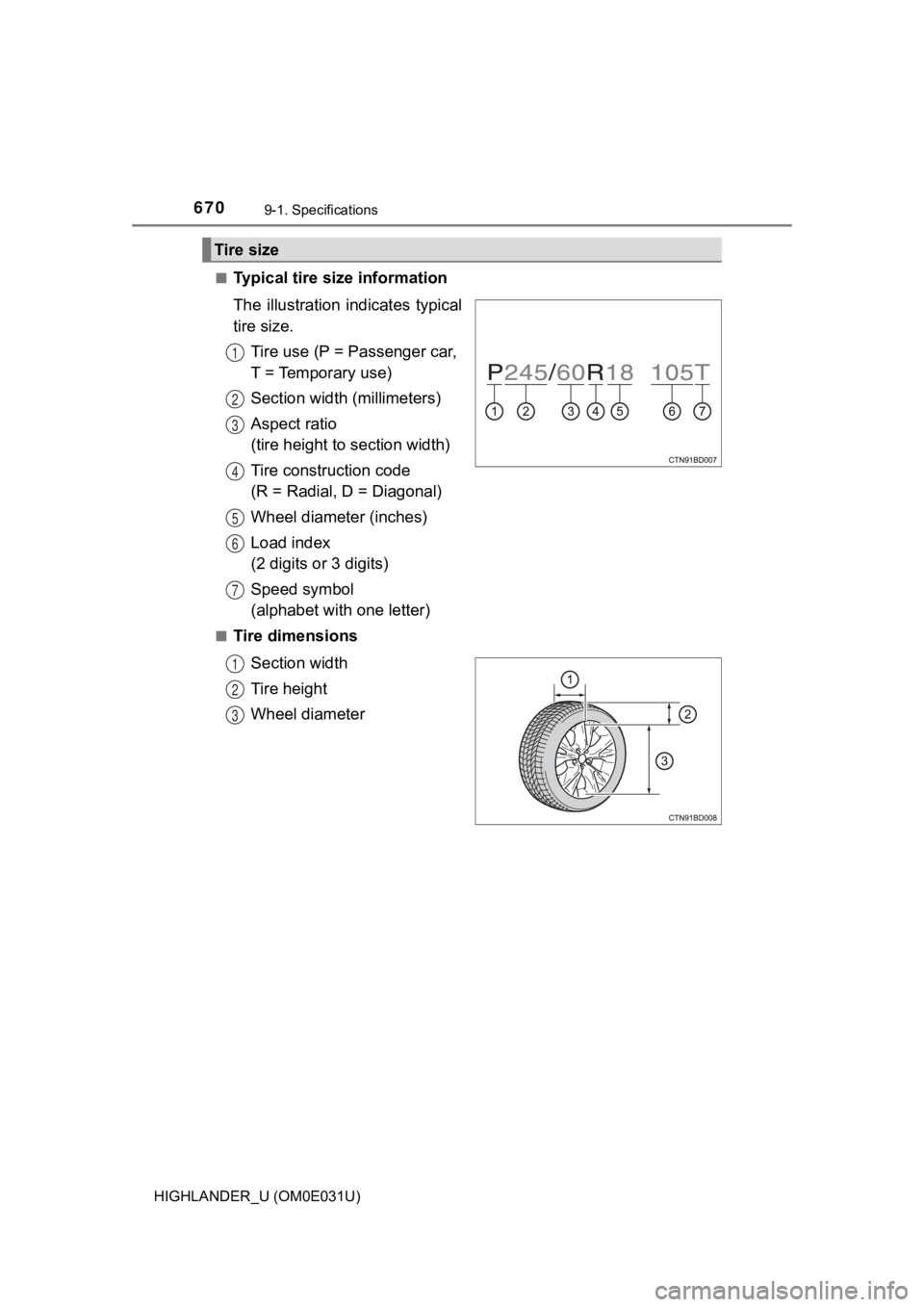
Typical tire size information
The illustration i
ndicates typical
tire size.
Tire use (P = Passenger car,
T = Temporary use)
Section widt h (millimeters)
Aspect ratio
(tire height to section width)
Tire construction code
(R = Radial, D = Diagonal)
Wheel diameter (inches)
Load index
(2 digits or 3 digits)
Speed symbol
(alphabet with one letter)
■Tire dimensions
Section width
Tire height
Wheel diameter
Tire size
1
2
3
4
5
6
7
1
2
3
Page 672 of 732
6729-1. Specifications
HIGHLANDER_U (OM0E031U)
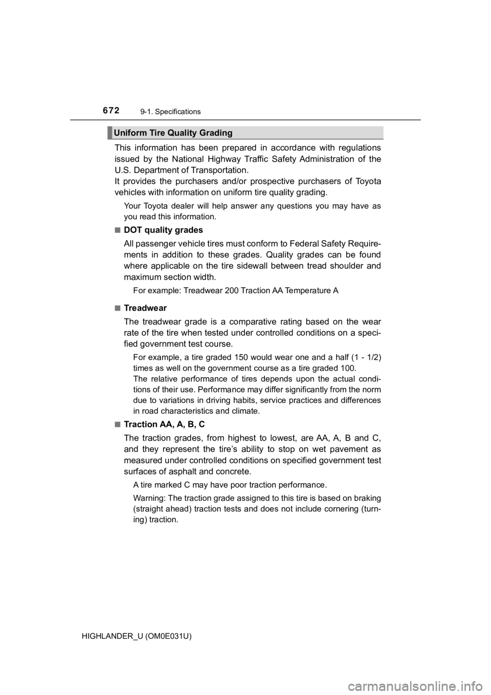
This information has been prepared in accordance with regulations
issued by the National Highway Tr affic Safety Administration of the
U.S. Department of Transportation.
It provides the purchasers and/or prospective purchasers of Toyota
vehicles with info rmation on uniform ti re quality grading.
Your Toyota dealer will help answer any questions you may have as
you read this information.
■DOT quality grades
All passenger vehicle tires must conform to Federal Safety Requ ire-
ments in addition to these grades. Quality grades can be found
where applicable on the tire sidewall between tread shoulder an d
maximum section width.
For example: Treadwear 200 Traction AA Temperature A
■Treadwear
The treadwear grade is a comparative rating based on the wear
rate of the tire when tested under controlled conditions on a s peci-
fied government t est course.
For example, a tire graded 150 would wear one and a half (1 - 1 /2)
times as well on the governmen t course as a tire graded 100.
The relative performance of tires depends upon the actual condi -
tions of their use. Performance ma y differ significantly from the norm
due to variations in driving habits, service practices and diff erences
in road characteristics and climate.
■Traction AA, A, B, C
The traction grades, from highest to lowest, are AA, A, B and C ,
and they represent the tire’s ability to stop on wet pavement a s
measured under controlled conditions on specified government te st
surfaces of asphalt and concrete.
A tire marked C may have p oor traction performance.
Warning: The traction grade assigned to this tire is based on b raking
(straight ahead) traction tests and does not include cornering (turn-
ing) traction.
Uniform Tire Quality Grading
Page 675 of 732
6759-1. Specifications
9
Vehicle specifications
HIGHLANDER_U (OM0E031U)
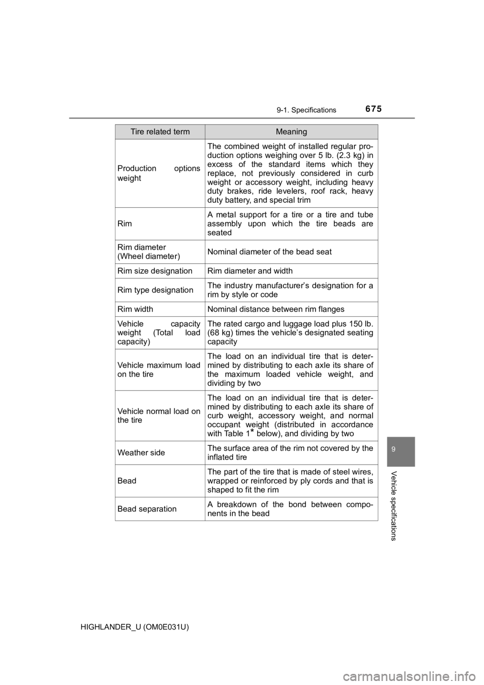
Production options
weight
The combined weight of installed regular pro-
duction options weighing over 5 lb. (2.3 kg) in
excess of the standard items which they
replace, not previously considered in curb
weight or accessory weight, including heavy
duty brakes, ride levelers, roof rack, heavy
duty battery, and special trim
Rim
A metal support for a tire or a tire and tube
assembly upon which the tire beads are
seated
Rim diameter
(Wheel diameter)Nominal diameter of the bead seat
Rim size designationRim diameter and width
Rim type designationThe industry manufacturer’s designation for a
rim by style or code
Rim widthNominal distance between rim flanges
Vehicle capacity
weight (Total load
capacity)The rated cargo and l uggage load plus 150 lb.
(68 kg) times the vehicle’s designated seating
capacity
Vehicle maximum load
on the tire
The load on an individual tire that is deter-
mined by distributing to each axle its share of
the maximum loaded vehicle weight, and
dividing by two
Vehicle normal load on
the tire
The load on an individual tire that is deter-
mined by distributing to each axle its share of
curb weight, accessory weight, and normal
occupant weight (distributed in accordance
with Table 1
* below), and dividing by two
Weather sideThe surface area of the rim not covered by the
inflated tire
Bead
The part of the tire that is made of steel wires,
wrapped or reinforced by ply cords and that is
shaped to fit the rim
Bead separationA breakdown of the bond between compo-
nents in the bead
Tire related termMeaning