rear view mirror TOYOTA HIGHLANDER 2018 (in English) User Guide
[x] Cancel search | Manufacturer: TOYOTA, Model Year: 2018, Model line: HIGHLANDER, Model: TOYOTA HIGHLANDER 2018Pages: 732, PDF Size: 14.5 MB
Page 168 of 732
1683-4. Adjusting the steering wheel and mirrors
HIGHLANDER_U (OM0E031U)
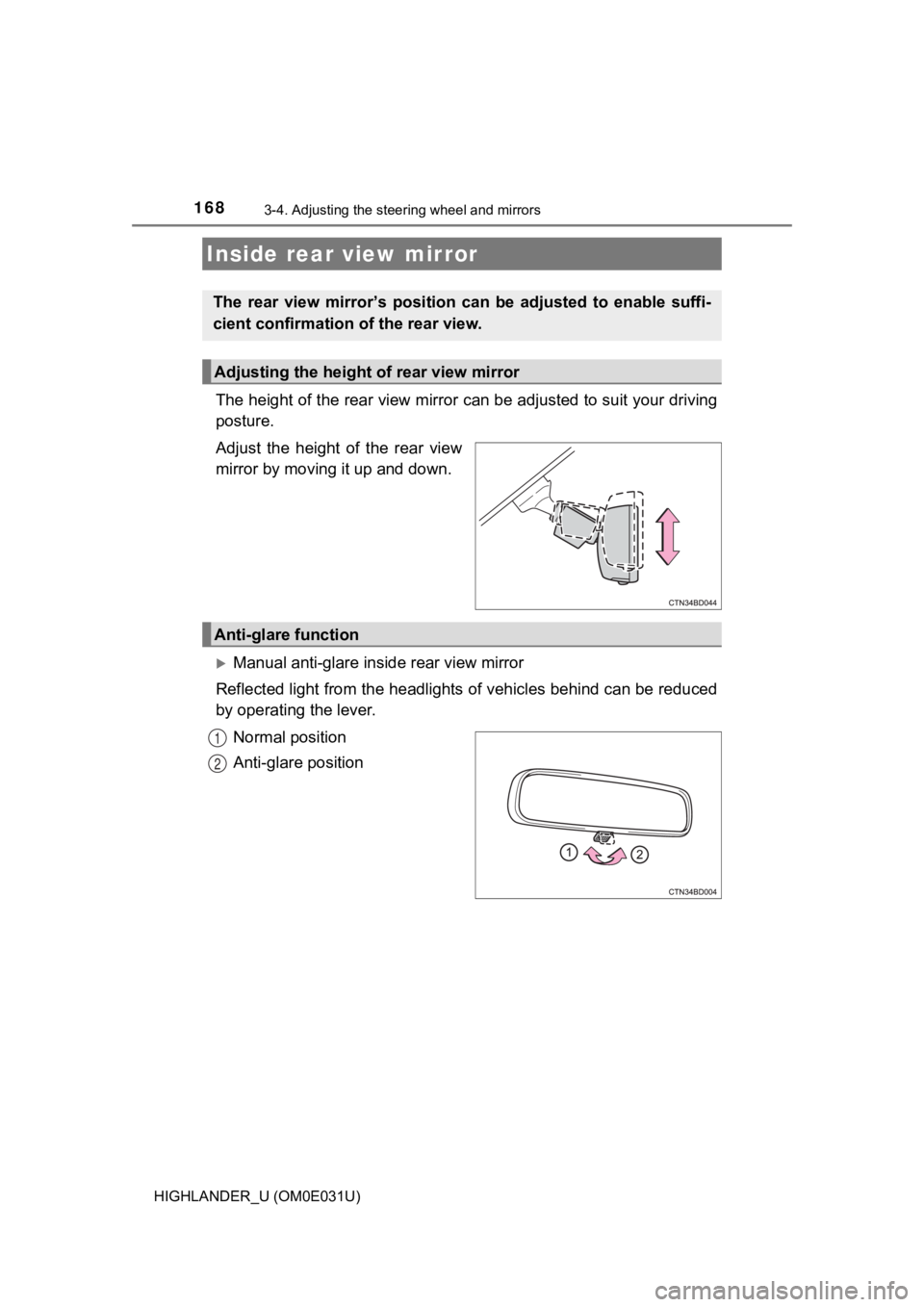
The height of the rear view mirror can be adjusted to suit your driving
posture.
Adjust the height of the rear view
mirror by moving it up and down.
Manual anti-glare inside rear view mirror
Reflected light from the headlights of vehicles behind can be r educed
by operating the lever.
Normal position
Anti-glare position
Inside rear view mirror
The rear view mirror’s position ca n be adjusted to enable suffi-
cient confirmation of the rear view.
Adjusting the height of rear view mirror
Anti-glare function
1
2
Page 169 of 732
1693-4. Adjusting the steering wheel and mirrors
3
Operation of each component
HIGHLANDER_U (OM0E031U)
Auto anti-glare inside rear view mirror
Responding to the level of brightness of the headlights of vehi cles
behind, the reflected light is automatically reduced.
Changing automatic anti- glare function mode
ON/OFF
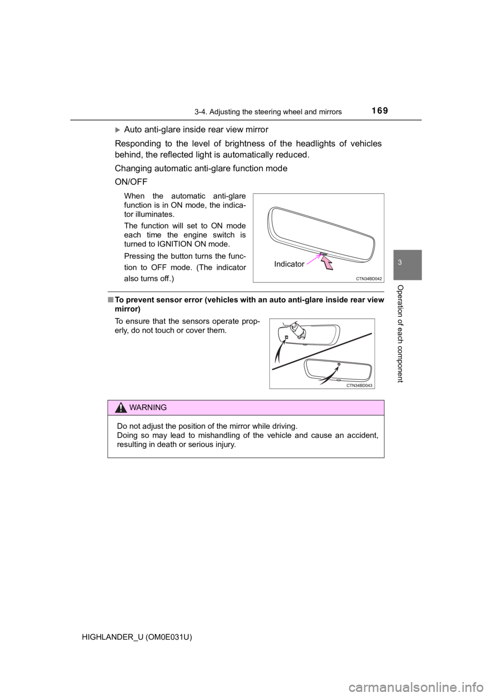
When the automatic anti-glare
function is in ON mode, the indica-
tor illuminates.
The function will set to ON mode
each time the engine switch is
turned to IGNITION ON mode.
Pressing the button turns the func-
tion to OFF mode. (The indicator
also turns off.)
■ To prevent sensor error (vehicles with an auto anti-glare insid e rear view
mirror)
Indicator
To ensure that the sensors operate prop-
erly, do not touch or cover them.
WARNING
Do not adjust the position of the mirror while driving.
Doing so may lead to mishandling of the vehicle and cause an ac cident,
resulting in death or serious injury.
Page 170 of 732
1703-4. Adjusting the steering wheel and mirrors
HIGHLANDER_U (OM0E031U)
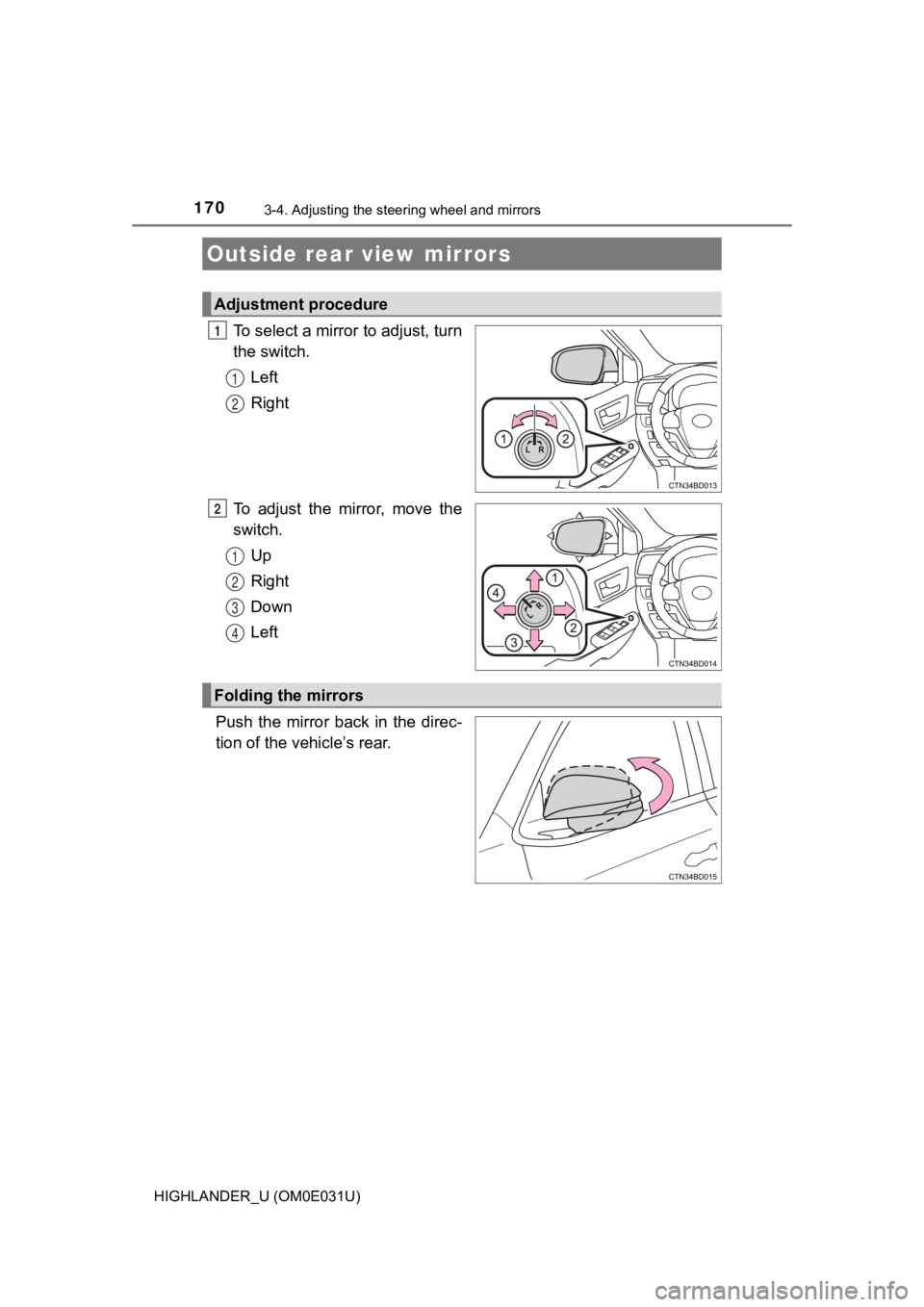
To select a mirror to adjust, turn
the switch.
Left
Right
To adjust the mirror, move the
switch. Up
Right
Down
Left
Push the mirror back in the direc-
tion of the vehicle’s rear.
Outside rear view mirrors
Adjustment procedure
1
1
2
2
1
2
3
4
Folding the mirrors
Page 171 of 732
1713-4. Adjusting the steering wheel and mirrors
3
Operation of each component
HIGHLANDER_U (OM0E031U)
■Mirror angle can be adjusted when
Vehicles without a smart key system
The engine switch is in the “ACC” or “ON” position.
Vehicles with a smart key system
The engine switch is in ACCESSORY or IGNITION ON mode.
■ When the mirrors are fogged up
The outside rear view mirrors can be cleared using the mirror d efoggers. Turn
on the rear window defogger to turn on the outside rear view mi rror defog-
gers. ( P. 438, 444)
■ Automatic adjustment of th e mirror angle (if equipped)
A desired mirror face angle can be entered to memory and recall ed automati-
cally by the driving position memory. ( P. 158)
WARNING
■Important points while driving
Observe the following precautions while driving.
Failure to do so may result in loss of control of the vehicle and cause an
accident, resulting in death or serious injury.
● Do not adjust the mirrors while driving.
● Do not drive with the mirrors folded.
● Both the driver and passenger side mirrors must be extended and properly
adjusted before driving.
■ When the mirror defoggers are operating
Do not touch the rear view mirror surfaces, as they can become very hot
and burn you.
Page 189 of 732
1894-1. Before driving
4
Driving
HIGHLANDER_U (OM0E031U)
WARNING
Observe the following precautions.
Failure to do so may result in death or serious injury.
■When driving the vehicle
● Use engine braking (downshift) to maintain a safe speed when driving
down a steep hill.
Using the brakes continuously may cause the brakes to overheat and lose
effectiveness. ( P. 227)
● Do not adjust the positions of the steering wheel, the seat, or the inside or
outside rear view mirrors while driving.
Doing so may result in a loss of vehicle control.
● Always check that all passengers’ arms, heads or other parts of their body
are not outside the vehicle.
● Do not drive in excess of the speed limit. Even if the legal sp eed limit per-
mits it, do not drive over 85 mph (140 km/h) unless your vehicl e has high-
speed capability tires. Driving over 85 mph (140 km/h) may resu lt in tire
failure, loss of control and possible injury. Be sure to consult a tire dealer
to determine whether the tires on your vehicle are high-speed c apability
tires or not before driving at such speeds.
■ When driving on slippery road surfaces
● Sudden braking, acceleration and steering may cause tire slippa ge and
reduce your ability to control the vehicle.
● Sudden acceleration, engine braking due to shifting, or changes in engine
speed could cause the vehicle to skid.
● After driving through a puddle, lightly depress the brake pedal to make
sure that the brakes are functioning properly. Wet brake pads m ay prevent
the brakes from functioning properly. If the brakes on only one side are wet
and not functioning properly, steering control may be affected.
Page 213 of 732
2134-1. Before driving
4
Driving
HIGHLANDER_U (OM0E031U)
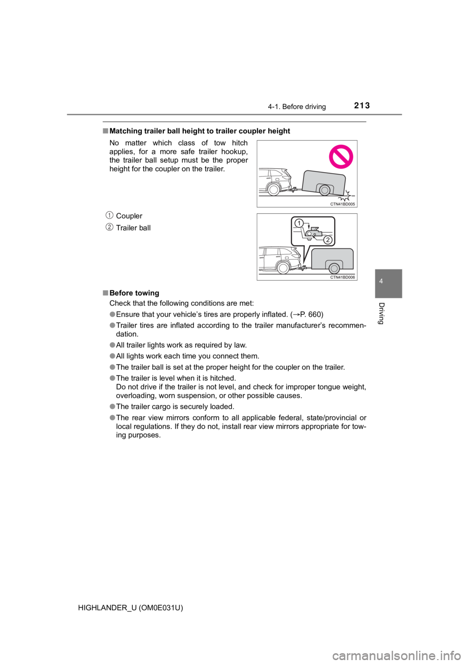
■Matching trailer ball height to trailer coupler height
■ Before towing
Check that the following conditions are met:
●Ensure that your vehicle’s tires are properly inflated. ( P. 660)
● Trailer tires are inflated according to the trailer manufacture r’s recommen-
dation.
● All trailer lights work as required by law.
● All lights work each time you connect them.
● The trailer ball is set at the proper height for the coupler on the trailer.
● The trailer is level when it is hitched.
Do not drive if the trailer is not level, and check for imprope r tongue weight,
overloading, worn suspension, or other possible causes.
● The trailer cargo is securely loaded.
● The rear view mirrors conform to all applicable federal, state/provincial or
local regulations. If they do not, install rear view mirrors ap propriate for tow-
ing purposes.
No matter which class of tow hitch
applies, for a more safe trailer hookup,
the trailer ball setup must be the proper
height for the coupler on the trailer.
Coupler
Trailer ball
1
2
Page 258 of 732
2584-5. Using the driving support systems
HIGHLANDER_U (OM0E031U)
WARNING
●Do not subject the camera sensor to a strong impact.
● Do not change the installation position or direction of the cam era sensor or
remove it.
● Do not disassemble the camera sensor.
● Do not modify any components of the vehicle around the camera s ensor
(inside rear view mirror, etc.) or ceiling.
● Do not attach any accessories that may obstruct the camera sens or to the
hood, front grille or front bumper. Contact your Toyota dealer for details.
● If a surfboard or other long object is to be mounted on the roo f, make sure
that it will not obstruct the camera sensor.
● Do not modify the headlights or other lights.
Page 273 of 732
2734-5. Using the driving support systems
4
Driving
HIGHLANDER_U (OM0E031U)●
Some pedestrians such as the following may not be detected by t he radar
sensor and camera sensor, preventing the system from operating prop-
erly
*2:
• Pedestrians shorter than approximately 3.2 ft. (1 m) or taller than approx-
imately 6.5 ft. (2 m)
• Pedestrians wearing oversized clothing (a rain coat, long skir t, etc.), mak-
ing their silhouette obscure
• Pedestrians who are carrying large baggage, holding an umbrella, etc., hiding part of their body
• Pedestrians who are bending forward or squatting
• Pedestrians who are pushing a stroller, wheelchair, bicycle or other vehi-
cle
• Groups of pedestrians which are close together
• Pedestrians who are wearing white and look extremely bright
• Pedestrians in the dark, such as at night or while in a tunnel
• Pedestrians whose clothing appears to be nearly the same color or
brightness as their surroundings
• Pedestrians near walls, fences, guardrails, or large objects
• Pedestrians who are on a metal object (manhole cover, steel plate, etc.)
on the road
• Pedestrians who are walking fast
• Pedestrians who are changing speed abruptly
• Pedestrians running out from behind a vehicle or a large objec t
• Pedestrians who are extremely close to the side of the vehicle (outside rear view mirror, etc.)
*2: For countries/areas specified as Region B (P. 261), the pedestrian
detection function may not be available.
■ If the PCS warning light flashes or illuminates and a warning m essage is
displayed on the multi-information display
The pre-collision system may be temporarily unavailable or ther e may be a
malfunction in the system.
● In the following situations, the warning light will turn off, t he message will
disappear and the system will become operational when normal op erating
conditions return:
• When the radar sensor or camera sensor or the area around eith er sen-
sor is hot, such as in the sun
• When the radar sensor or camera sensor or the area around eith er sen-
sor is cold, such as in an extremely cold environment
• When a front sensor is dirty or covered with snow, etc.
• When the part of the windshield in front of the camera sensor is fogged
up or covered with condensation or ice
(Defogging the windshield: P. 437, 444)
• If the camera sensor is obstructed, such as when the hood is open or a sticker is attached to the windshield near the camera sensor
Page 315 of 732
3154-5. Using the driving support systems
4
Driving
HIGHLANDER_U (OM0E031U)
WARNING
●In low temperatures, the screen may darken or the image may bec ome
faint. The image could distort when the vehicle is moving, or y ou may
become unable to see the image on the screen. Be sure to check direct
visually and with the mirrors al l around the vehicle before pro ceeding.
● If the tire sizes are changed, the position of the fixed guide lines displayed
on the screen may change.
● The camera uses a special lens. The distances between objects a nd
pedestrians that appear in the image displayed on the screen will differ
from the actual distances. ( P. 310)
NOTICE
■How to use the camera
● The rear view monitor system may not operate properly in the fo llowing
cases.
• If the back of the vehicle is hit, the position and mounting a ngle of the
camera may change.
• As the camera has a water proof construction, do not detach, disassem- ble or modify it. This may cause incorrect operation.
• When cleaning the camera lens, flush the camera with a large quantity
of water and wipe it with a soft and wet cloth. Strongly rubbin g the cam-
era lens may cause the camera lens to be scratched and unable t o
transmit a clear image.
• Do not allow organic solvent, car wax, window cleaner or glass coat to
adhere to the camera. If this happens, wipe it off as soon as possible.
• If the temperature changes rapidly, such as when hot water is poured
on the vehicle in cold weather, the system may not operate norm ally.
• When washing the vehicle, do not apply intensive bursts of wat er to the
camera or camera area. Doing so may result in the camera malfun c-
tioning.
• When the camera is used under fluorescent lights, sodium light or mer-
cury light etc., the lights and the illuminated areas may appea r to flicker.
● Do not expose the camera to strong impact as this could cause a malfunc-
tion. If this happens, have the vehicle inspected by your Toyot a dealer as
soon as possible.
Page 317 of 732
3174-5. Using the driving support systems
4
Driving
HIGHLANDER_U (OM0E031U)
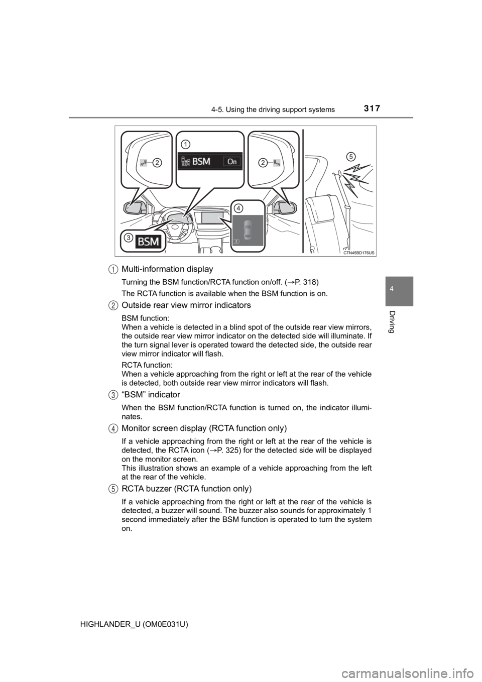
Multi-information display
Turning the BSM function/RCTA function on/off. (P. 318)
The RCTA function is available when the BSM function is on.
Outside rear view mirror indicators
BSM function:
When a vehicle is detected in a blind spot of the outside rear view mirrors,
the outside rear view mirror indicator on the detected side will illuminate. If
the turn signal lever is operated toward the detected side, the outside rear
view mirror indicator will flash.
RCTA function:
When a vehicle approaching from the right or left at the rear o f the vehicle
is detected, both outside rear view mirror indicators will flas h.
“BSM” indicator
When the BSM function/RCTA function is turned on, the indicator illumi-
nates.
Monitor screen display (RCTA function only)
If a vehicle approaching from the right or left at the rear of the vehicle is
detected, the RCTA icon ( P. 325) for the detected side will be displayed
on the monitor screen.
This illustration shows an example of a vehicle approaching fro m the left
at the rear of the vehicle.
RCTA buzzer (RCTA function only)
If a vehicle approaching from the right or left at the rear of the vehicle is
detected, a buzzer will sound. The buzzer also sounds for approximately 1
second immediately after the BSM function is operated to turn t he system
on.
1
2
3
4
5