clock TOYOTA HIGHLANDER 2021 Owners Manual (in English)
[x] Cancel search | Manufacturer: TOYOTA, Model Year: 2021, Model line: HIGHLANDER, Model: TOYOTA HIGHLANDER 2021Pages: 568, PDF Size: 29.17 MB
Page 82 of 568
822-1. Instrument cluster
HIGHLANDER_U
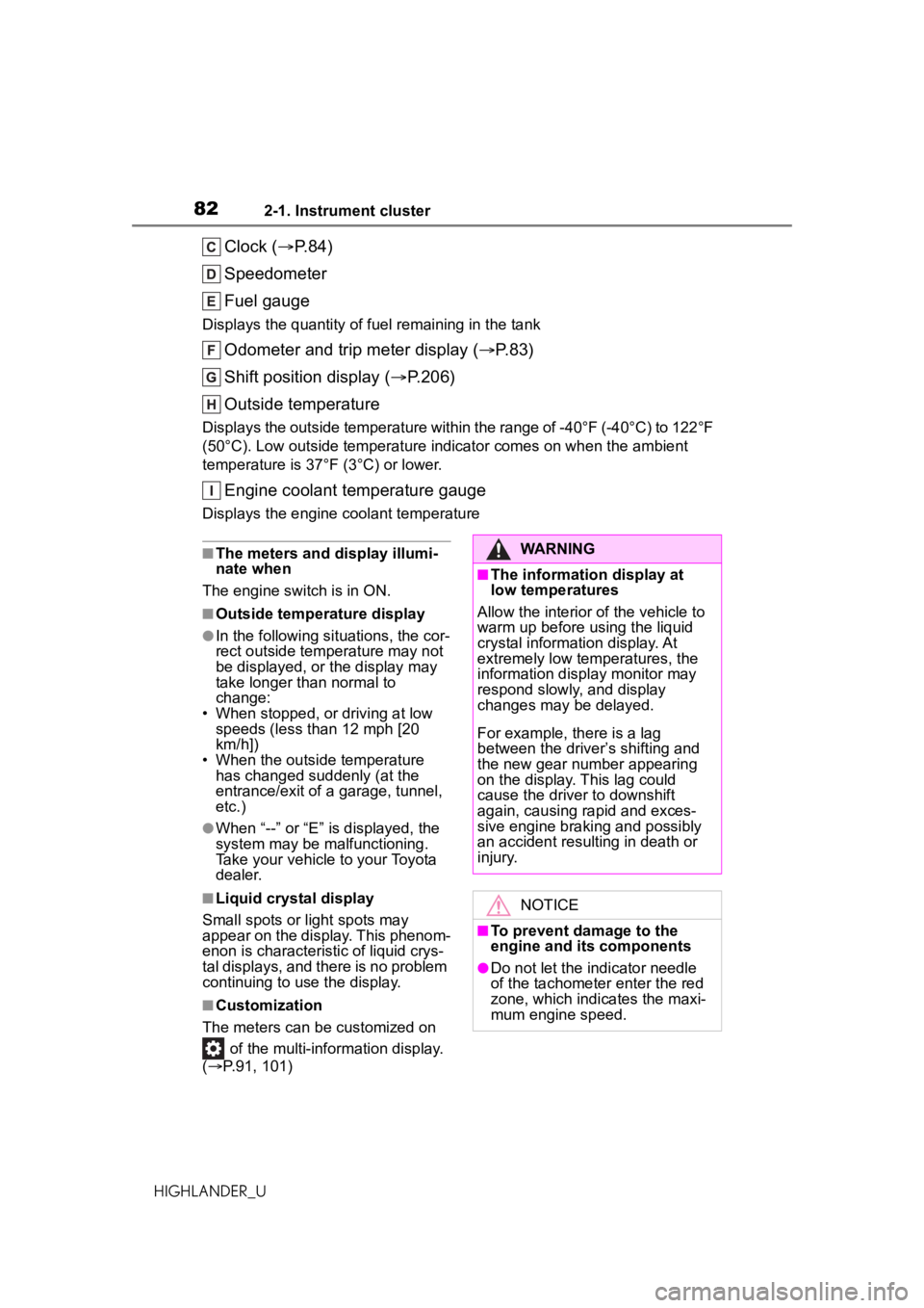
Clock (P.84)
Speedometer
Fuel gauge
Displays the quantity of fu el remaining in the tank
Odometer and trip meter display ( P.83)
Shift position display ( P.206)
Outside temperature
Displays the outside temperature within the range of -40°F (-40°C) to 122°F
(50°C). Low outside temperature indicator comes on when the ambient
temperature is 37°F (3°C) or lower.
Engine coolant temperature gauge
Displays the engine c oolant temperature
■The meters and display illumi-
nate when
The engine switch is in ON.
■Outside temperature display
●In the following si tuations, the cor-
rect outside tempe rature may not
be displayed, or the display may
take longer than normal to
change:
• When stopped, or driving at low
speeds (less than 12 mph [20
km/h])
• When the outside temperature
has changed suddenly (at the
entrance/exit of a garage, tunnel,
etc.)
●When “--” or “E” is displayed, the
system may be malfunctioning.
Take your vehicle to your Toyota
dealer.
■Liquid crystal display
Small spots or light spots may
appear on the display. This phenom-
enon is characteristi c of liquid crys-
tal displays, and there is no problem
continuing to use the display.
■Customization
The meters can be customized on of the multi-information display.
( P.91, 101)
WARNING
■The information display at
low temperatures
Allow the interior of the vehicle to
warm up before using the liquid
crystal information display. At
extremely low temperatures, the
information disp lay monitor may
respond slowly, and display
changes may be delayed.
For example, there is a lag
between the driver’s shifting and
the new gear number appearing
on the display. This lag could
cause the driver to downshift
again, causing rapid and exces-
sive engine braking and possibly
an accident resulting in death or
injury.
NOTICE
■To prevent damage to the
engine and its components
●Do not let the indicator needle
of the tachometer enter the red
zone, which indicates the maxi-
mum engine speed.
Page 84 of 568
842-1. Instrument cluster
HIGHLANDER_UThis image is for example only, and
may differ from the actual vehicle.
1
Darker
2 Brighter
■Brightness of the meters (day
mode and night mode)
The brightness of the meters is
changed between day mode and
night mode.
●Day mode: When the surrounding
area is bright
●Night mode: When the surround-
ing area is dark
The clocks can be adjusted on
the audio system screen.
Refer to “NAVIGATION AND
MULTIMEDIA SYSTEM
OWNER’S MANUAL”.
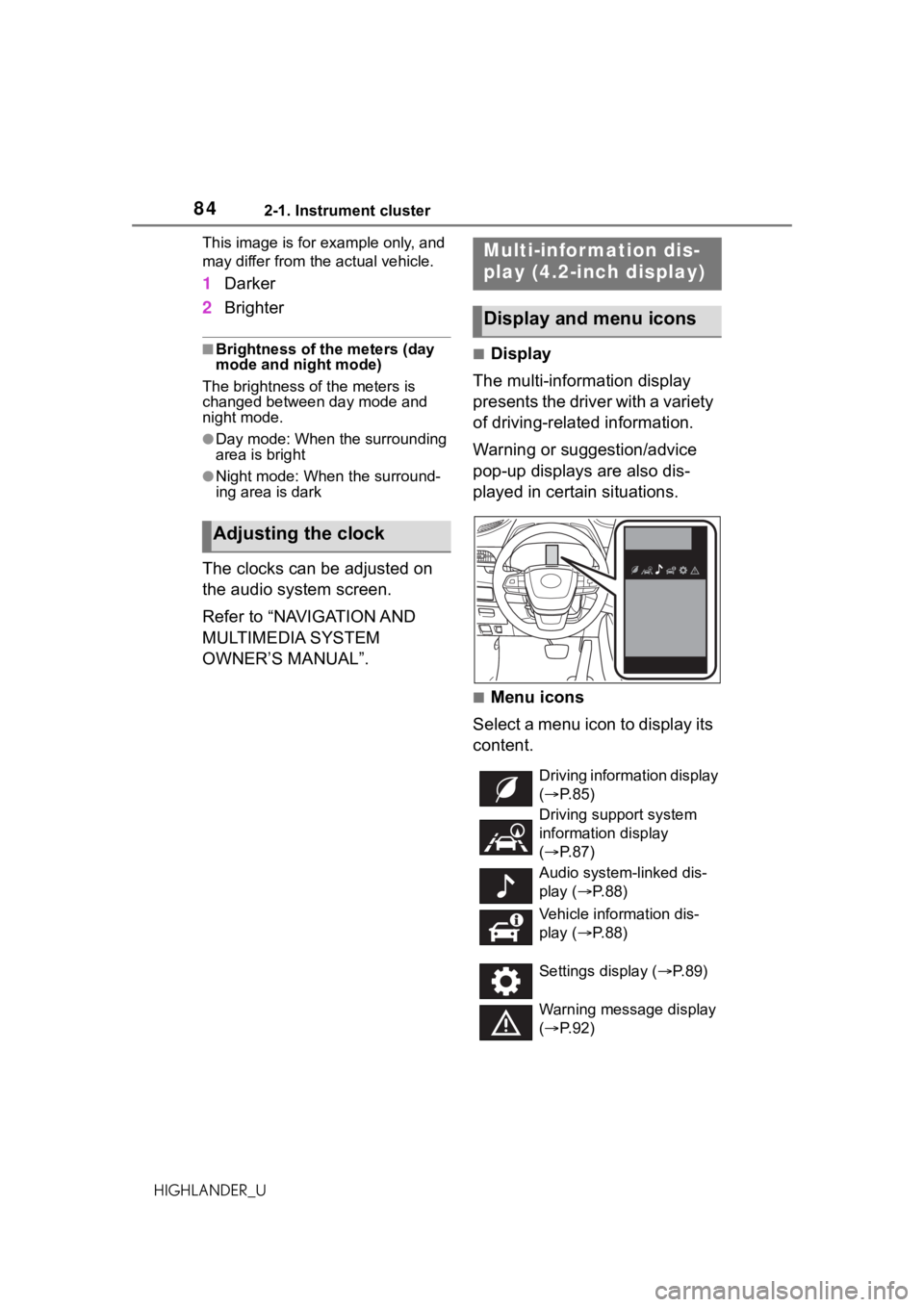
■Display
The multi-information display
presents the driver with a variety
of driving-related information.
Warning or suggestion/advice
pop-up displays are also dis-
played in certain situations.
■Menu icons
Select a menu icon to display its
content.
Adjusting the clock
Multi-infor mation dis-
play (4.2-inch display)
Display and menu icons
Driving information display
( P. 8 5 )
Driving support system
information display
( P. 8 7 )
Audio system-linked dis-
play ( P. 8 8 )
Vehicle information dis-
play ( P. 8 8 )
Settings display ( P.89)
Warning message display
( P. 9 2 )
Page 336 of 568
3365-2. Using the air conditioning system and defogger
HIGHLANDER_U
5-2.Using the air conditioning system and defogger
*: If equipped
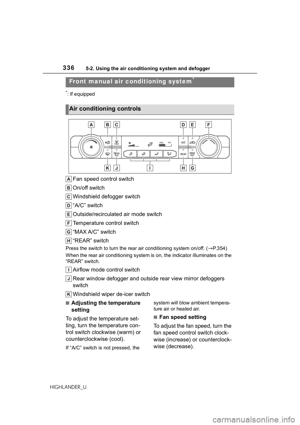
Fan speed control switch
On/off switch
Windshield defogger switch
“A/C” switch
Outside/recirculated air mode switch
Temperature control switch
“MAX A/C” switch
“REAR” switch
Press the switch to turn the rear air conditioning system on/off. (P.354)
When the rear air conditioning system is on, the indicator illuminates on the
“REAR” switch.
Airflow mode control switch
Rear window defogger and outside rear view mirror defoggers
switch
Windshield wiper de-icer switch
■Adjusting the temperature
setting
To adjust the temperature set-
ting, turn the temperature con-
trol switch clockwise (warm) or
counterclockwise (cool).
If “A/C” switch is not pressed, the system will blow ambient tempera-
ture air or heated air.
■Fan speed setting
To adjust the fan speed, turn the
fan speed control switch clock-
wise (increase) or counterclock-
wise (decrease).
Front manual air c onditioning system*
Air conditioning controls
Page 342 of 568
3425-2. Using the air conditioning system and defogger
HIGHLANDER_U
switch
Windshield wiper de-icer switch
■Adjusting the temperature
setting
Turn driver’s side temperature
control switch clockwise to
increases the temperature and
turn the switch counterclockwise
to decreases the temperature.
If “A/C” switch is not pressed, the
system will blow a mbient tempera-
ture air or heated air.
The temperature for the driver,
front passenger and rear seats
can be adjusted separately
when:
“SYNC” control knob is
moved upward or downward.
(The “PASS” and “REAR” dis-
plays disappear)
The passenger’s side tem-
perature control switch is
turned. (The “PASS” display
disappears)
The rear seat temperature
contorl knob is moved upward
or downward. (The “REAR”
display disappears)
To the air conditioning system
switches between individual and
simultaneous modes move “SYNC”
control knob upward or downward.
■Setting the fan speed
To set the fan speed, move the
fan speed control knob upward
or downward.
Upward: Increases the fan speed Downward: Decreases the fan
speed
Pressing the “OFF” switch to turns
off the fan.
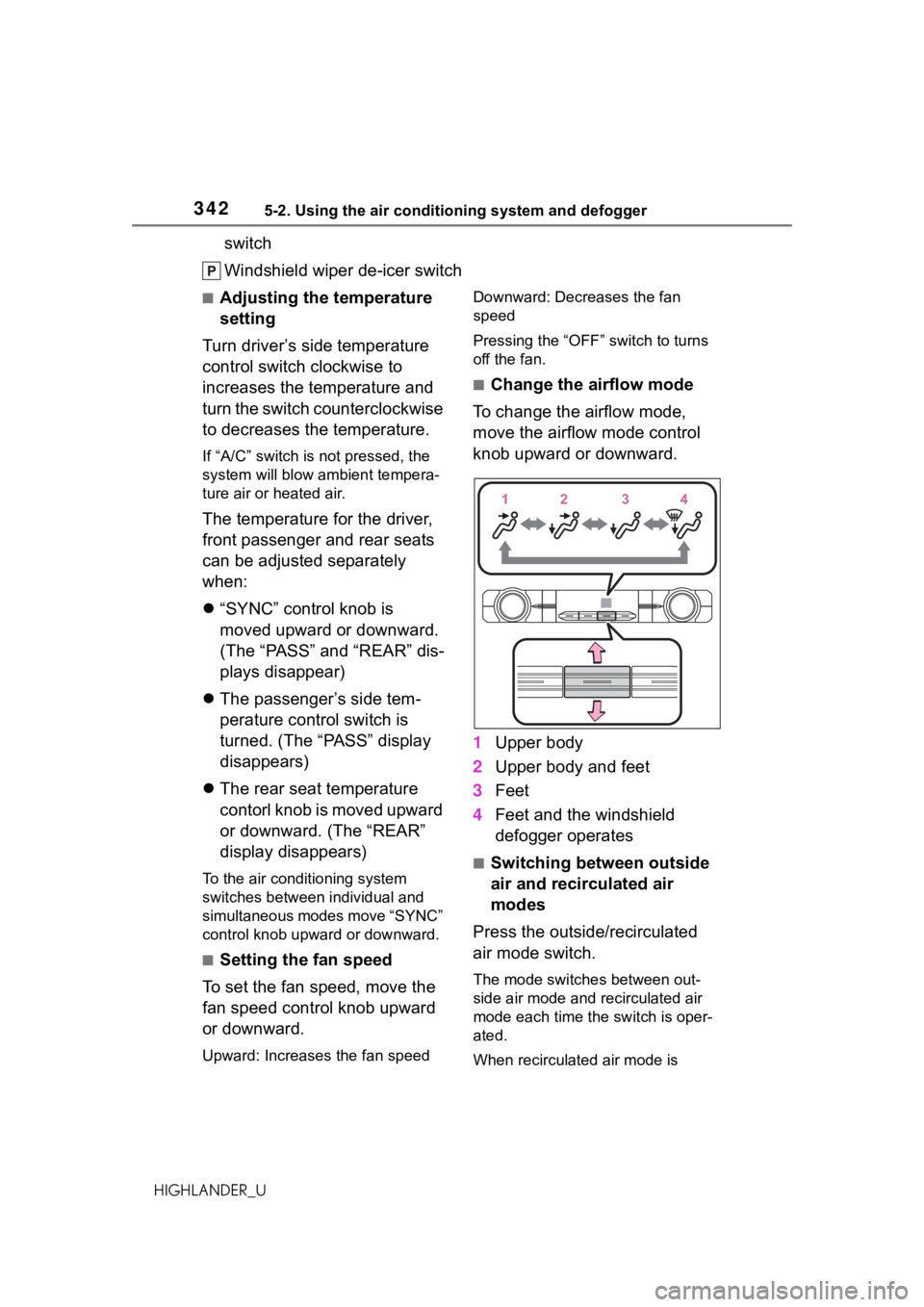
■Change the airflow mode
To change the airflow mode,
move the airflow mode control
knob upward or downward.
1 Upper body
2 Upper body and feet
3 Feet
4 Feet and the windshield
defogger operates
■Switching between outside
air and recirculated air
modes
Press the outside/recirculated
air mode switch.
The mode switches between out-
side air mode and recirculated air
mode each time the switch is oper-
ated.
When recirculated air mode is
Page 413 of 568
4136-3. Do-it-yourself maintenance
6
Maintenance and care
HIGHLANDER_U
more than 5 minutes for the
oil to drain back into the bot-
tom of the engine.
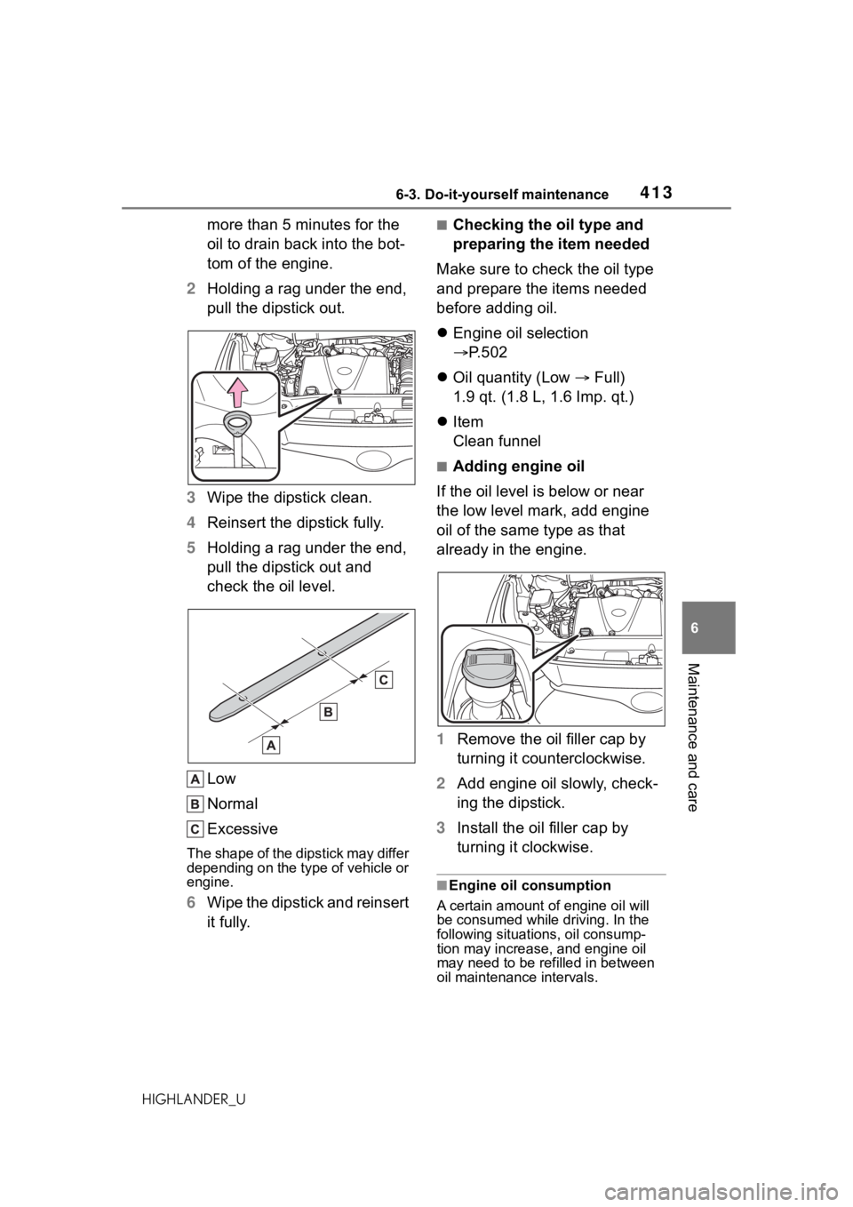
2 Holding a rag under the end,
pull the dipstick out.
3 Wipe the dipstick clean.
4 Reinsert the dipstick fully.
5 Holding a rag under the end,
pull the dipstick out and
check the oil level.
Low
Normal
Excessive
The shape of the dipstick may differ
depending on the type of vehicle or
engine.
6Wipe the dipstick and reinsert
it fully.
■Checking the oil type and
preparing the item needed
Make sure to check the oil type
and prepare the items needed
before adding oil.
Engine oil selection
P.502
Oil quantity (Low Full)
1.9 qt. (1.8 L, 1.6 Imp. qt.)
Item
Clean funnel
■Adding engine oil
If the oil level is below or near
the low level mark, add engine
oil of the same type as that
already in the engine.
1 Remove the oil filler cap by
turning it counterclockwise.
2 Add engine oil slowly, check-
ing the dipstick.
3 Install the oil filler cap by
turning it clockwise.
■Engine oil consumption
A certain amount of engine oil will
be consumed while driving. In the
following situatio ns, oil consump-
tion may increase, and engine oil
may need to be refilled in between
oil maintenance intervals.
Page 442 of 568
4426-3. Do-it-yourself maintenance
HIGHLANDER_U
Back-up lights
License plate lights
■Lights that need to be
replaced by your Toyota
dealer
Headlight low beams
Headlight high beams
Daytime running lights (types
A and C)
Daytime running lights/park-
ing lights (type B)
Front fog lights (if equipped)
Side turn signal lights
Tail lights/stop lights
Rear side marker lights
Tail lights
High mounted stoplight
Outer foot lights (if equipped)
■LED lights
The lights other than the following
lights each consist of a number of
LEDs. If any of the LEDs burn out,
take your vehicle to your Toyota
dealer to have the light replaced.
●Front turn signal lights/parking
lights (types A and C)
●Front turn signal lights (type B)
●Front side marker lights
●Rear turn signal lights
●Back-up lights
●License plate lights
■Condensation build-up on the
inside of the lens
Temporary condensation build-up
on the inside of the light lens does
not indicate a malfunction. Contact
your Toyota dealer for more informa- tion in the following situations:
●Large drops of water have built up
on the inside of the lens.
●Water has built up
inside the light.
■When replacing light bulbs
P.439
■Front turn signal
lights/parking lights (types
A and C) and front turn sig-
nal lights (type B)
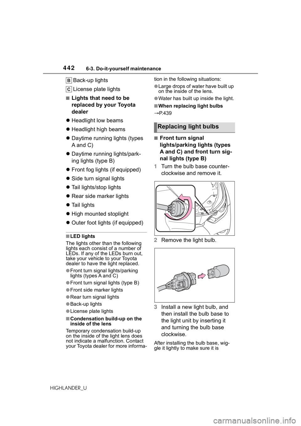
1 Turn the bulb base counter-
clockwise and remove it.
2 Remove the light bulb.
3 Install a new light bulb, and
then install the bulb base to
the light unit by inserting it
and turning the bulb base
clockwise.
After installing the bulb base, wig-
gle it lightly to make sure it is
Replacing light bulbs
Page 443 of 568
4436-3. Do-it-yourself maintenance
6
Maintenance and care
HIGHLANDER_Usecurely installed and turn the lights
and turn signal li
ghts on to visually
check that there is no light leaking
from between the bulb base and
light unit.
■Front side marker lights
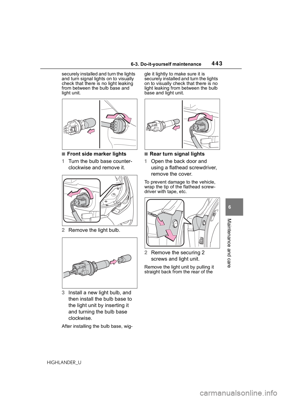
1 Turn the bulb base counter-
clockwise and remove it.
2 Remove the light bulb.
3 Install a new light bulb, and
then install the bulb base to
the light unit by inserting it
and turning the bulb base
clockwise.
After installing th e bulb base, wig- gle it lightly to make sure it is
securely installed a
nd turn the lights
on to visually check that there is no
light leaking from between the bulb
base and light unit.
■Rear turn signal lights
1 Open the back door and
using a flathead screwdriver,
remove the cover.
To prevent damage to the vehicle,
wrap the tip of th e flathead screw-
driver with tape, etc.
2 Remove the securing 2
screws and light unit.
Remove the light u nit by pulling it
straight back from the rear of the
Page 444 of 568
4446-3. Do-it-yourself maintenance
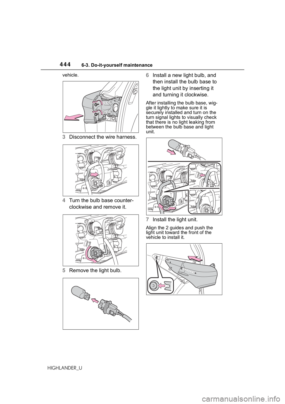
HIGHLANDER_Uvehicle.
3
Disconnect the wire harness.
4 Turn the bulb base counter-
clockwise and remove it.
5 Remove the light bulb. 6
Install a new light bulb, and
then install the bulb base to
the light unit by inserting it
and turning it clockwise.
After installing the bulb base, wig-
gle it lightly to make sure it is
securely installed and turn on the
turn signal lights to visually check
that there is no light leaking from
between the bulb base and light
unit.
7Install the light unit.
Align the 2 guides and push the
light unit toward the front of the
vehicle to install it.
Page 445 of 568
4456-3. Do-it-yourself maintenance
6
Maintenance and care
HIGHLANDER_U
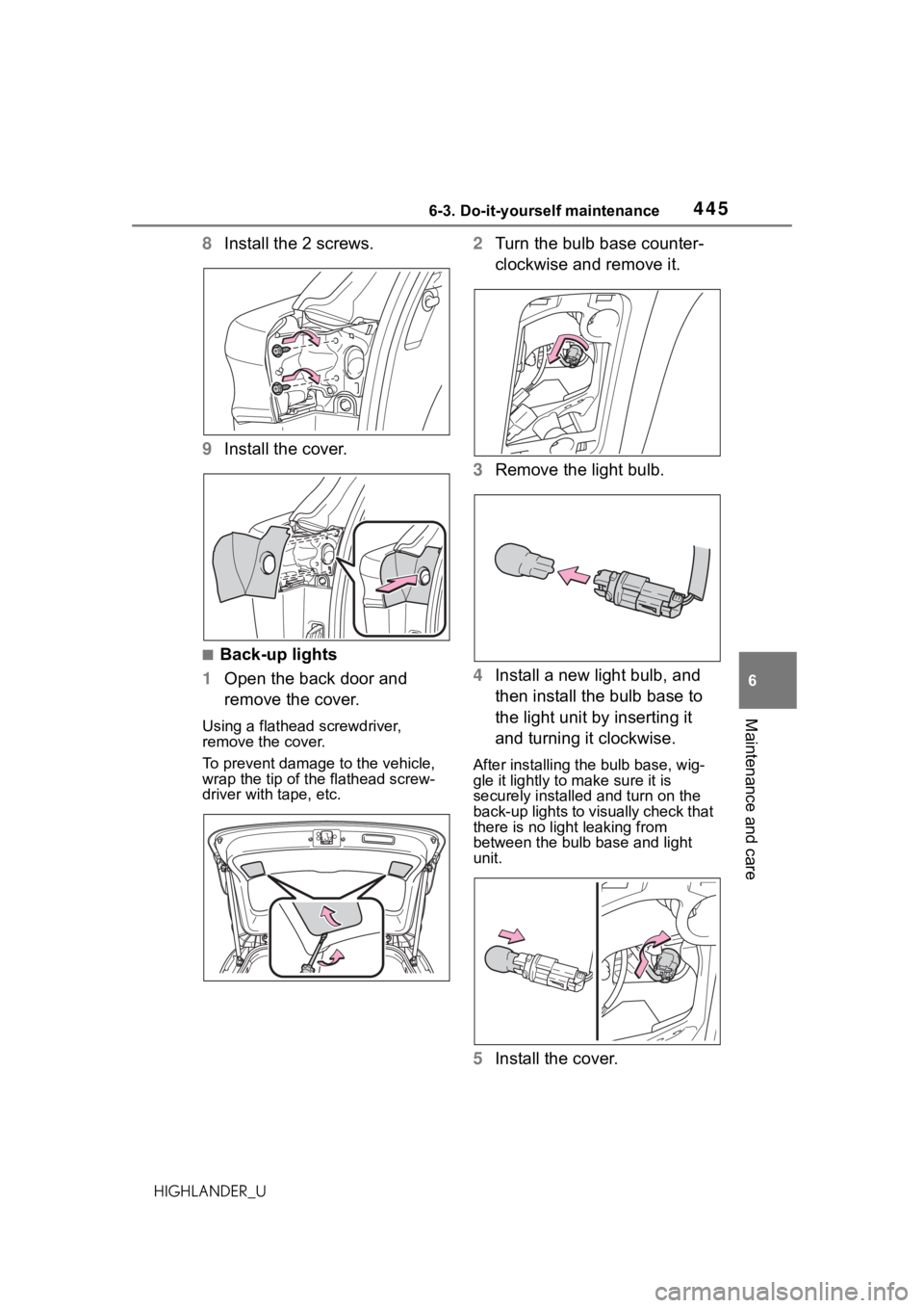
8Install the 2 screws.
9 Install the cover.
■Back-up lights
1 Open the back door and
remove the cover.
Using a flathead screwdriver,
remove the cover.
To prevent damage to the vehicle,
wrap the tip of the flathead screw-
driver with tape, etc.
2Turn the bulb base counter-
clockwise and remove it.
3 Remove the light bulb.
4 Install a new light bulb, and
then install the bulb base to
the light unit by inserting it
and turning it clockwise.
After installing the bulb base, wig-
gle it lightly to make sure it is
securely installed and turn on the
back-up lights to visually check that
there is no light leaking from
between the bulb base and light
unit.
5Install the cover.
Page 476 of 568
4767-2. Steps to take in an emergency
HIGHLANDER_U
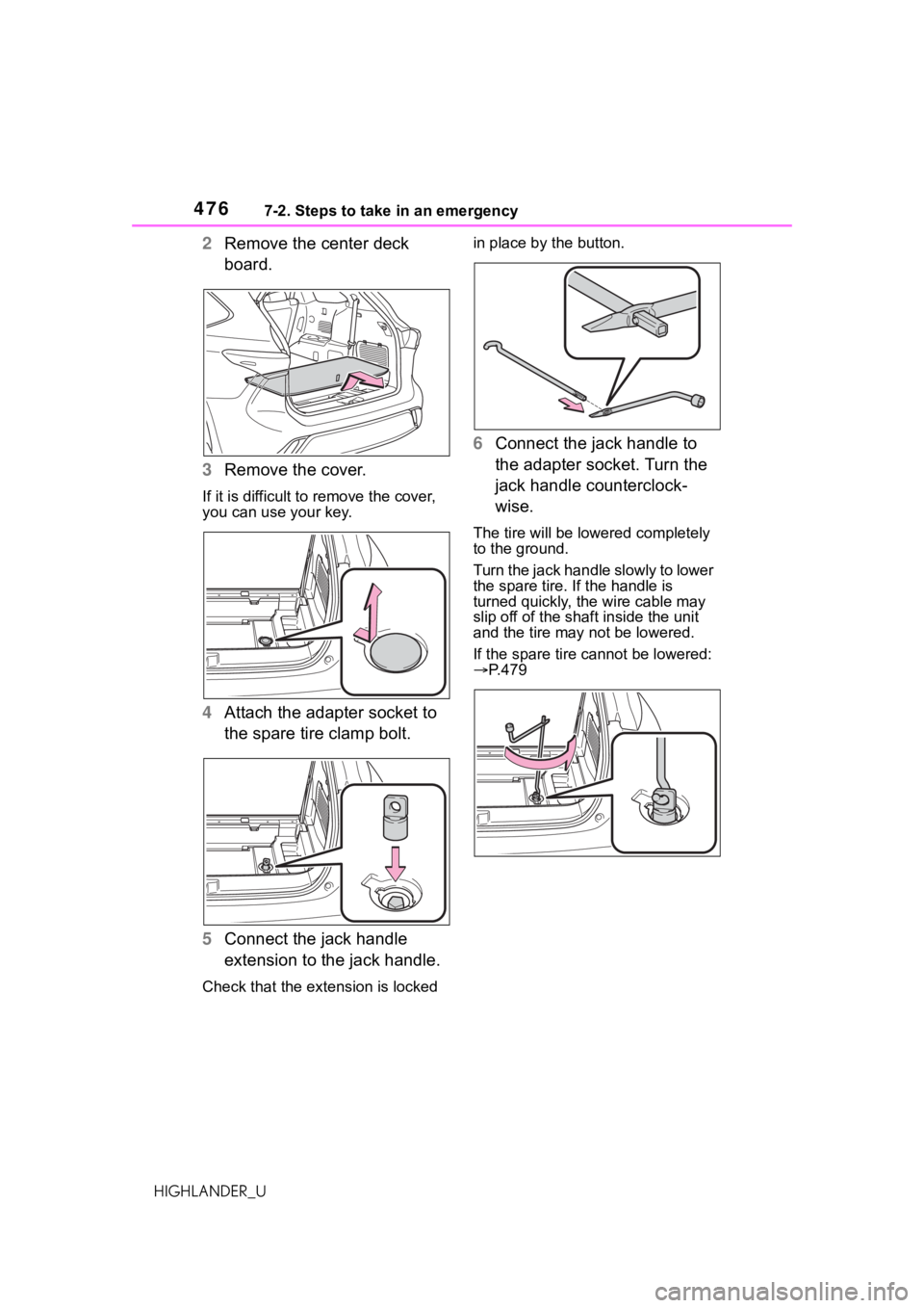
2Remove the center deck
board.
3 Remove the cover.
If it is difficult to remove the cover,
you can use your key.
4Attach the adapter socket to
the spare tire clamp bolt.
5 Connect the jack handle
extension to the jack handle.
Check that the extension is locked in place by the button.
6
Connect the jack handle to
the adapter socket. Turn the
jack handle counterclock-
wise.
The tire will be low ered completely
to the ground.
Turn the jack handle slowly to lower
the spare tire. If the handle is
turned quickly, the wire cable may
slip off of the shaf t inside the unit
and the tire may not be lowered.
If the spare tire cannot be lowered:
P.479