tire pressure TOYOTA HIGHLANDER 2021 (in English) Service Manual
[x] Cancel search | Manufacturer: TOYOTA, Model Year: 2021, Model line: HIGHLANDER, Model: TOYOTA HIGHLANDER 2021Pages: 568, PDF Size: 15.96 MB
Page 474 of 568
4747-2. Steps to take in an emergency
HIGHLANDER_U
When replacing tires on a vehi-
cle with wheel lock nuts, use the
following procedures to remove
and install the wheel lock nuts.
The wheel lock key is stored in
the tray inside the luggage com-partment. Always return the
wheel lock key to its original
position after use, so that it does
not get lost. (
P.473)
■Removal
For ease of removal, the wheel
lock nut should always be the
first one loosened.
1 Place the wheel lock key on
top of the wheel lock nut,
turning until the wheel lock
key and wheel lock nut pat-
terns engage.
2 Place the wheel nut wrench
on the wheel lock key, and
while applying pressure on
the wheel lock key, loosen
the wheel lock nut.
■Installation
For ease of installation, the
wheel lock nut should always be
the last one tightened.
1 By hand, install a wheel lock
nut on each wheel.
2 Place the wheel lock key on
top of the wheel lock nut,
turning until the wheel lock
key and wheel lock nut pat-
terns engage.
3 Place the wheel nut wrench
on the wheel lock key, and
while applying pressure on
the wheel lock key, tighten
the wheel lock nut to the rec-
ommended torque.
WARNING
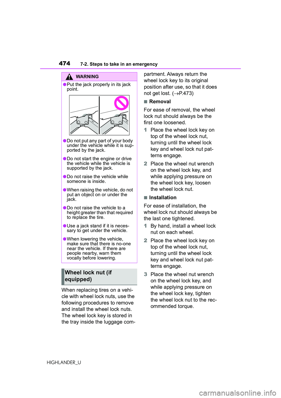
●Put the jack properly in its jack
point.
●Do not put any part of your body
under the vehicle while it is sup-
ported by the jack.
●Do not start the engine or drive
the vehicle while the vehicle is
supported by the jack.
●Do not raise the vehicle while
someone is inside.
●When raising the vehicle, do not
put an object on or under the
jack.
●Do not raise the vehicle to a
height greater than that required
to replace the tire.
●Use a jack stand if it is neces-
sary to get under the vehicle.
●When lowering the vehicle,
make sure that there is no-one
near the vehicle. If there are
people nearby, warn them
vocally before lowering.
Wheel lock nut (if
equipped)
Page 483 of 568
4837-2. Steps to take in an emergency
7
When trouble arises
HIGHLANDER_U
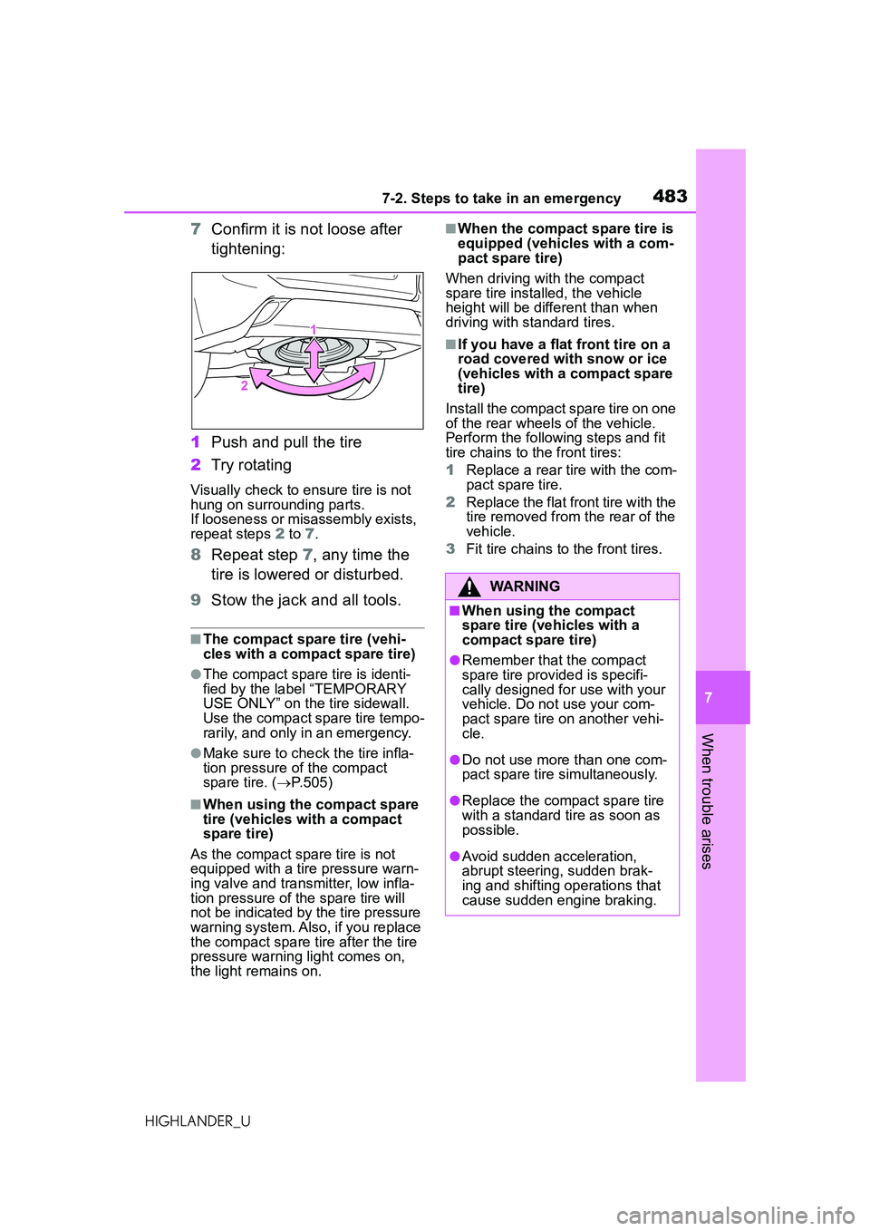
7Confirm it is not loose after
tightening:
1 Push and pull the tire
2 Try rotating
Visually check to ensure tire is not
hung on surrounding parts.
If looseness or misassembly exists,
repeat steps 2 to 7 .
8Repeat step 7, any time the
tire is lowered or disturbed.
9 Stow the jack and all tools.
■The compact spare tire (vehi-
cles with a compact spare tire)
●The compact spare tire is identi-
fied by the label “TEMPORARY
USE ONLY” on the tire sidewall.
Use the compact spare tire tempo-
rarily, and only in an emergency.
●Make sure to che ck the tire infla-
tion pressure of the compact
spare tire. ( P.505)
■When using the compact spare
tire (vehicles with a compact
spare tire)
As the compact spare tire is not
equipped with a tire pressure warn-
ing valve and transmitter, low infla-
tion pressure of the spare tire will
not be indicated by the tire pressure
warning system. Also, if you replace
the compact spare tire after the tire
pressure warning light comes on,
the light remains on.
■When the compact spare tire is
equipped (vehicles with a com-
pact spare tire)
When driving with the compact
spare tire installed, the vehicle
height will be different than when
driving with standard tires.
■If you have a flat front tire on a
road covered with snow or ice
(vehicles with a compact spare
tire)
Install the compact spare tire on one
of the rear wheels of the vehicle.
Perform the following steps and fit
tire chains to the front tires:
1 Replace a rear tire with the com-
pact spare tire.
2 Replace the flat front tire with the
tire removed from the rear of the
vehicle.
3 Fit tire chains to the front tires.
WARNING
■When using the compact
spare tire (vehicles with a
compact spare tire)
●Remember that the compact
spare tire provided is specifi-
cally designed for use with your
vehicle. Do not use your com-
pact spare tire on another vehi-
cle.
●Do not use more than one com-
pact spare tire simultaneously.
●Replace the compact spare tire
with a standard tire as soon as
possible.
●Avoid sudden acceleration,
abrupt steering, sudden brak-
ing and shifting operations that
cause sudden engine braking.
Page 484 of 568
4847-2. Steps to take in an emergency
HIGHLANDER_U
WARNING
■When the compact spare tire
is attached (vehicles with a
compact spare tire)
The vehicle speed may not be
correctly detected, and the follow-
ing systems may not operate cor-
rectly:
• ABS & Brake assist
• VSC
• TRAC
• EPS
• Dynamic radar cruise control with full-speed range
• PCS (Pre-Collision System)
• LTA (Lane Tracing Assist)
• RSA (Road Sign Assist) (if equipped)
• Automatic High Beam
• AFS (Adaptive Front-lighting System) (if equipped)
• Tire pressure warning system
• Intuitive parking assist (if equipped)
• PKSB (Parking Support Brake) (if equipped)
• Toyota parking assist monitor (if equipped)
• Panoramic view monitor (if equipped)
• BSM (Blind Spot Monitor) (if equipped)
• Navigation system (if equipped)
Also, not only can the following
system not be utilized fully, but it
may even negatively affect the
drive-train components:
• AWD system (AWD models)
■Speed limit when using the
compact spare tire (vehicles
with a compact spare tire)
Do not drive at speeds in excess
of 50 mph (80 km/h) when a com-
pact spare tire is installed on the
vehicle.
The compact spare tire is not
designed for driving at high
speeds. Failure to observe this
precaution may lead to an acci-
dent causing death or serious
injury.
■After using the tools and jack
Before driving, make sure all the
tools and jack are securely in
place in their storage location to
reduce the possibility of personal
injury during a collision or sudden
braking.
NOTICE
■Be careful when driving over
bumps with the compact
spare tire installed on the
vehicle (vehicles with a com-
pact spare tire)
The vehicle becomes lower when
driving with the compact spare tire
compared to when driving with
standard tires. Be careful when
driving over uneven road sur-
faces.
■Driving with tire chains and
the compact spare tire (vehi-
cles with a compact spare
tire)
Do not fit tire chains to the com-
pact spare tire. Tire chains may
damage the vehicle body and
adversely affect driving perfor-
mance.
Page 485 of 568
4857-2. Steps to take in an emergency
7
When trouble arises
HIGHLANDER_U
NOTICE
■When replacing the tires
When removing or fitting the
wheels, tires or t he tire pressure
warning valve and transmitter,
contact your Toyota dealer as the
tire pressure warning valve and
transmitter may be damaged if not
handled correctly.
■When stowing the flat tire
●Ensure that there is no object
caught between the tire and the
vehicle underbody.
●Securely tighten the spare tire
clamp bolt to hold the spare
wheel carrier by the hook.
●Stow the flat tire in the spare tire
location. Failure to do so may
cause damage to the spare tire
carrier. Proper storage reduces
the possibility of injury in a colli-
sion or during sudden braking.
●Have the flat tire repaired and
the spare tire replaced with it as
soon as possible.
■Proper storage of the spare
tire
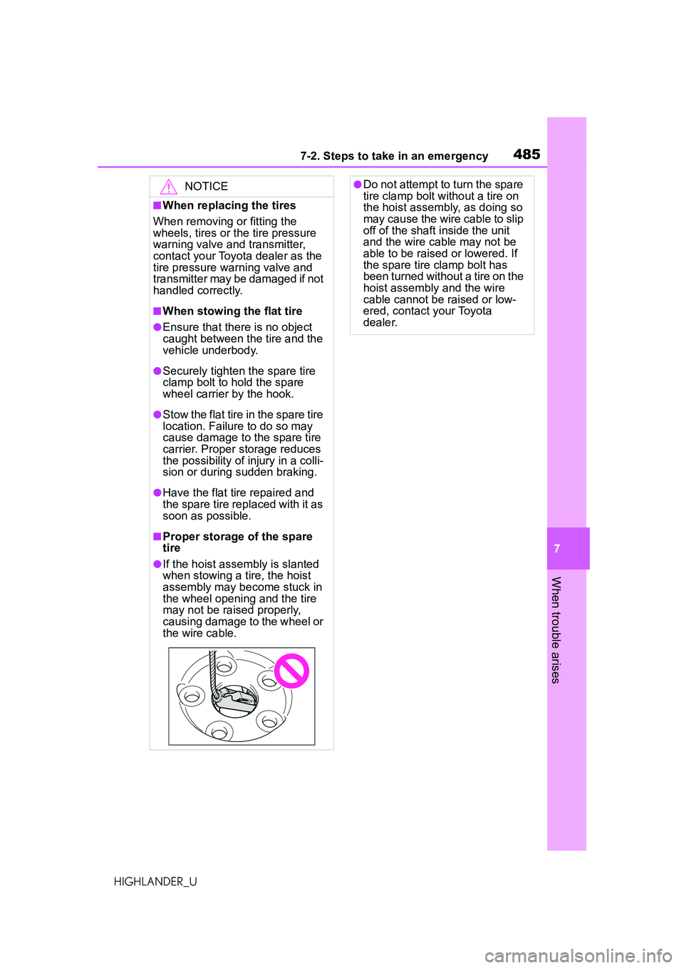
●If the hoist assembly is slanted
when stowing a tire, the hoist
assembly may become stuck in
the wheel opening and the tire
may not be raised properly,
causing damage to the wheel or
the wire cable.
●Do not attempt to turn the spare
tire clamp bolt without a tire on
the hoist assembly, as doing so
may cause the wire cable to slip
off of the shaft inside the unit
and the wire cable may not be
able to be raised or lowered. If
the spare tire clamp bolt has
been turned without a tire on the
hoist assembly and the wire
cable cannot be raised or low-
ered, contact your Toyota
dealer.
Page 505 of 568
5058-1. Specifications
8
Vehicle specifications
HIGHLANDER_U
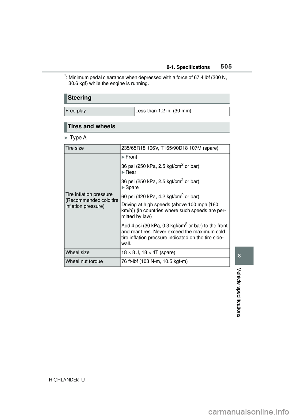
*: Minimum pedal clearance when depressed with a force of 67.4 lbf (300 N, 30.6 kgf) while the engine is running.
Ty p e A
Steering
Free playLess than 1.2 in. (30 mm)
Tires and wheels
Tire size235/65R18 106V, T165/90D18 107M (spare)
Tire inflation pressure
(Recommended cold tire
inflation pressure)
Front
36 psi (250 kPa, 2.5 kgf/cm
2 or bar)
Rear
36 psi (250 kPa, 2.5 kgf/cm
2 or bar)
Spare
60 psi (420 kPa, 4.2 kgf/cm
2 or bar)
Driving at high speeds (above 100 mph [160
km/h]) (in countries where such speeds are per-
mitted by law)
Add 4 psi (30 kPa, 0.3 kgf/cm
2 or bar) to the front
and rear tires. Never exceed the maximum cold
tire inflation pressure indicated on the tire side-
wall.
Wheel size18 8 J, 18 4T (spare)
Wheel nut torque76 ft•lbf (103 N•m, 10.5 kgf•m)
Page 506 of 568
5068-1. Specifications
HIGHLANDER_U
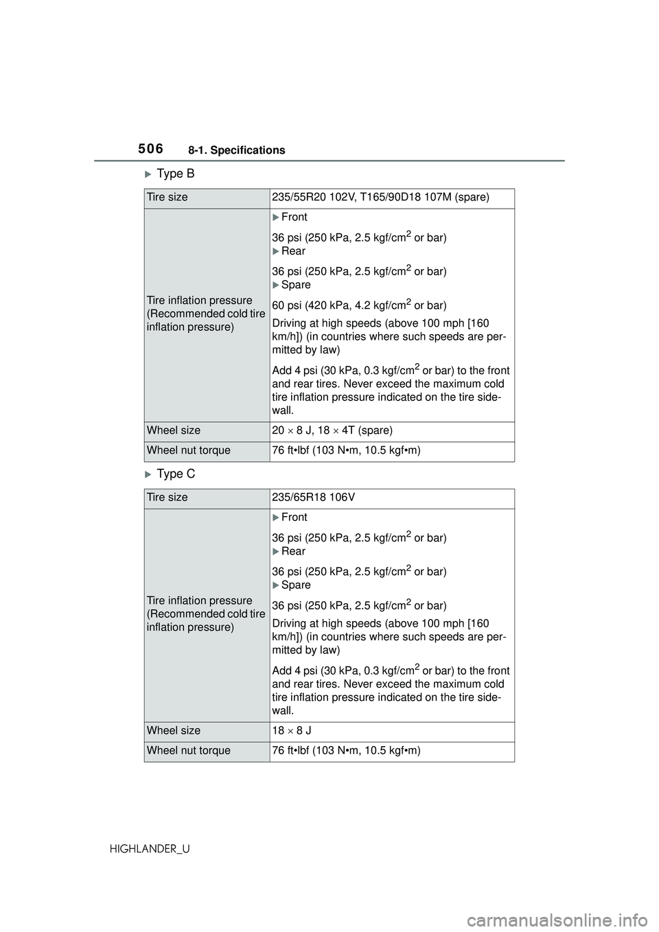
Ty p e B
Ty p e C
Tire size235/55R20 102V, T165/90D18 107M (spare)
Tire inflation pressure
(Recommended cold tire
inflation pressure)
Front
36 psi (250 kPa, 2.5 kgf/cm
2 or bar)
Rear
36 psi (250 kPa, 2.5 kgf/cm
2 or bar)
Spare
60 psi (420 kPa, 4.2 kgf/cm
2 or bar)
Driving at high speeds (above 100 mph [160
km/h]) (in countries where such speeds are per-
mitted by law)
Add 4 psi (30 kPa, 0.3 kgf/cm
2 or bar) to the front
and rear tires. Never exceed the maximum cold
tire inflation pressure indicated on the tire side-
wall.
Wheel size20 8 J, 18 4T (spare)
Wheel nut torque76 ft•lbf (103 N•m, 10.5 kgf•m)
Tire size235/65R18 106V
Tire inflation pressure
(Recommended cold tire
inflation pressure)
Front
36 psi (250 kPa, 2.5 kgf/cm
2 or bar)
Rear
36 psi (250 kPa, 2.5 kgf/cm
2 or bar)
Spare
36 psi (250 kPa, 2.5 kgf/cm
2 or bar)
Driving at high speeds (above 100 mph [160
km/h]) (in countries where such speeds are per-
mitted by law)
Add 4 psi (30 kPa, 0.3 kgf/cm
2 or bar) to the front
and rear tires. Never exceed the maximum cold
tire inflation pressure indicated on the tire side-
wall.
Wheel size18 8 J
Wheel nut torque76 ft•lbf (103 N•m, 10.5 kgf•m)
Page 507 of 568
5078-1. Specifications
8
Vehicle specifications
HIGHLANDER_U
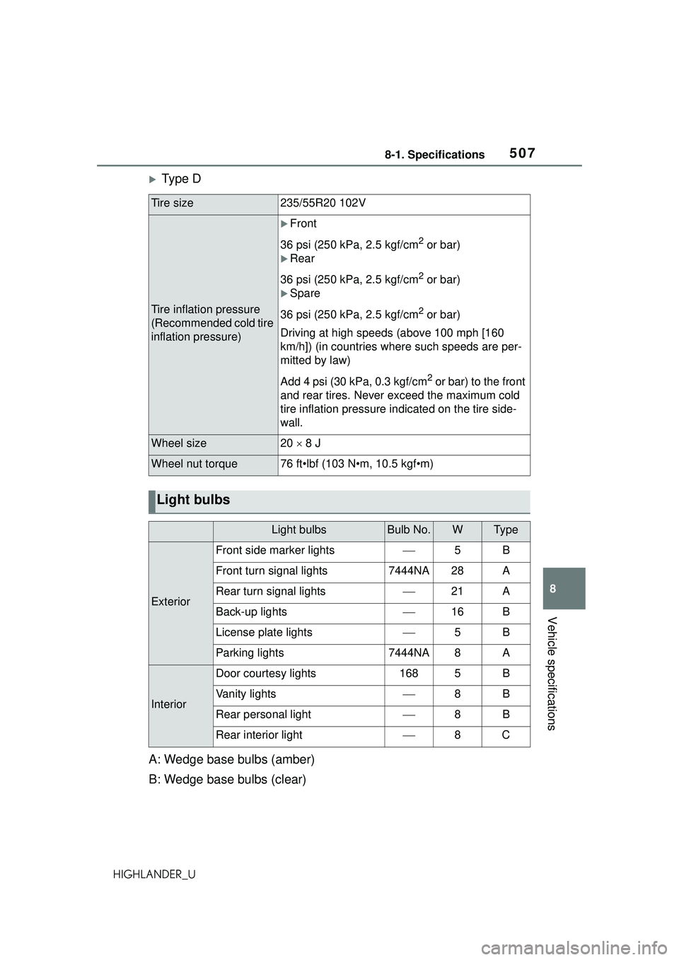
Ty p e D
A: Wedge base bulbs (amber)
B: Wedge base bulbs (clear)
Tire size235/55R20 102V
Tire inflation pressure
(Recommended cold tire
inflation pressure)
Front
36 psi (250 kPa, 2.5 kgf/cm
2 or bar)
Rear
36 psi (250 kPa, 2.5 kgf/cm
2 or bar)
Spare
36 psi (250 kPa, 2.5 kgf/cm
2 or bar)
Driving at high speeds (above 100 mph [160
km/h]) (in countries where such speeds are per-
mitted by law)
Add 4 psi (30 kPa, 0.3 kgf/cm
2 or bar) to the front
and rear tires. Never exceed the maximum cold
tire inflation pressure indicated on the tire side-
wall.
Wheel size20 8 J
Wheel nut torque76 ft•lbf (103 N•m, 10.5 kgf•m)
Light bulbs
Light bulbsBulb No.WTy p e
Exterior
Front side marker lights5B
Front turn signal lights7444NA28A
Rear turn signal lights21A
Back-up lights16B
License plate lights5B
Parking lights7444NA8A
Interior
Door courtesy lights1685B
Vanity lights8B
Rear personal light8B
Rear interior light8C
Page 512 of 568
5128-1. Specifications
HIGHLANDER_UA radial tire has “RADIAL” on the sidewall. A tire not marked “RADIAL” is a
bias-ply tire.
TUBELESS or TUBE TYPE
A tubeless tire does not have a tube and air is directly put into the tire. A
tube type tire has a tube inside the tire and the tube maintains the air pres-
sure.
Load limit at maximum cold tire inflation pressure (
P.420)
Maximum cold tire inflation pressure ( P.505)
This means the pressure to wh ich a tire may be inflated.
Uniform tire quality grading
For details, see “Uniform Tire Quality Grading” that follows.
Summer tires or all season tires ( P.420)
An all season tire has “M+S” on the si dewall. A tire not marked “M+S” is a
summer tire.
“TEMPORARY USE ONLY”
A compact spare tire is identified by the phrase “TEMPORARY USE ONLY”
molded on its sidewall. This tire is designed for temporary emergency use
only.
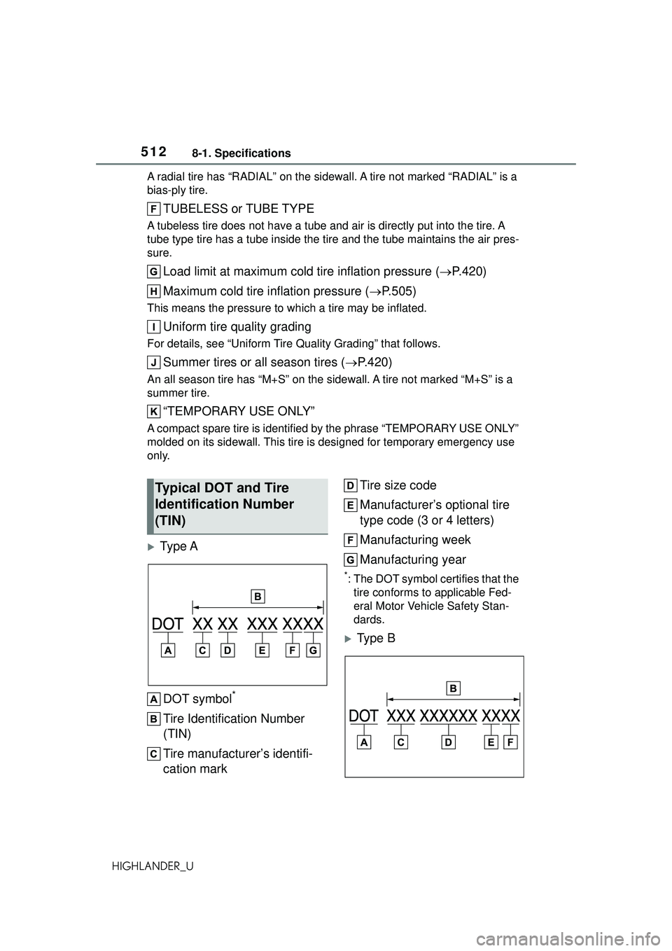
Ty p e A
DOT symbol
*
Tire Identification Number
(TIN)
Tire manufacturer’s identifi-
cation mark Tire size code
Manufacturer’s optional tire
type code (3 or 4 letters)
Manufacturing week
Manufacturing year
*:The DOT symbol ce
rtifies that the
tire conforms to applicable Fed-
eral Motor Vehicle Safety Stan-
dards.
Type B
Typical DOT and Tire
Identification Number
(TIN)
Page 515 of 568
5158-1. Specifications
8
Vehicle specifications
HIGHLANDER_UGrade C corresponds to a level of
performance which all passenger
car tires must meet under the Fed-
eral Motor Vehicle Safety Standard
No. 109.
Grades B and A represent higher
levels of performance on the labo-
ratory test wheel than the minimum
required by law.
Warning: The temperature grades
of a tire assume that it is properly
inflated and not overloaded.
Excessive speed, underinflation, or
excessive loading, either sepa-
rately or in combination, can cause
heat buildup and possible tire fail-
ure.
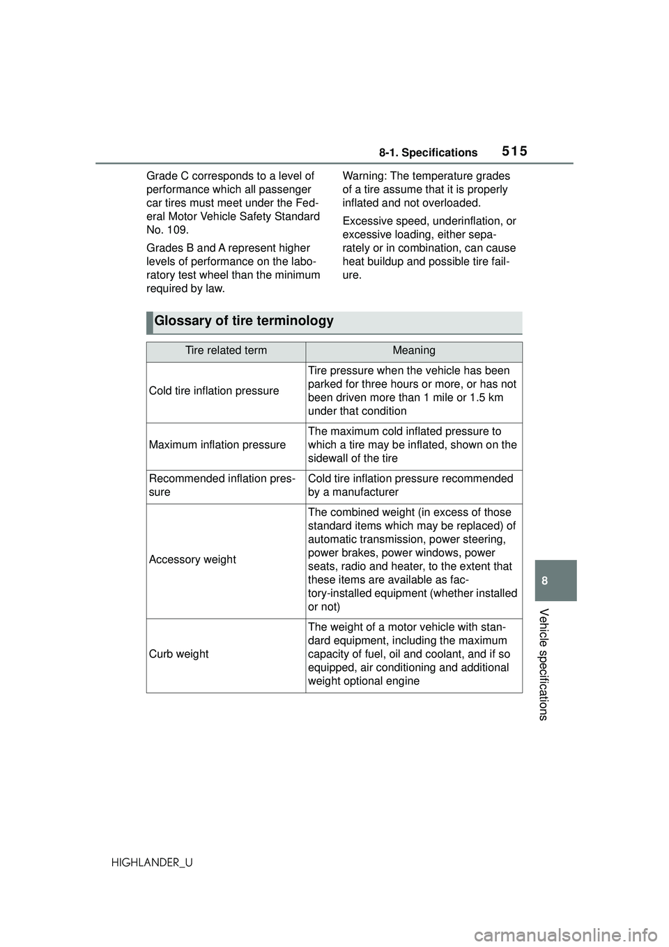
Glossary of tire terminology
Tire related termMeaning
Cold tire infl
ation pressure
Tire pressure when the vehicle has been
parked for three hours or more, or has not
been driven more than 1 mile or 1.5 km
under that condition
Maximum inflation pressure
The maximum cold inflated pressure to
which a tire may be inflated, shown on the
sidewall of the tire
Recommended inflation pres-
sureCold tire inflation pressure recommended
by a manufacturer
Accessory weight
The combined weight (in excess of those
standard items which may be replaced) of
automatic transmission, power steering,
power brakes, power windows, power
seats, radio and heater, to the extent that
these items are available as fac-
tory-installed equipment (whether installed
or not)
Curb weight
The weight of a motor vehicle with stan-
dard equipment, including the maximum
capacity of fuel, oil and coolant, and if so
equipped, air conditioning and additional
weight optional engine
Page 518 of 568
5188-1. Specifications
HIGHLANDER_U
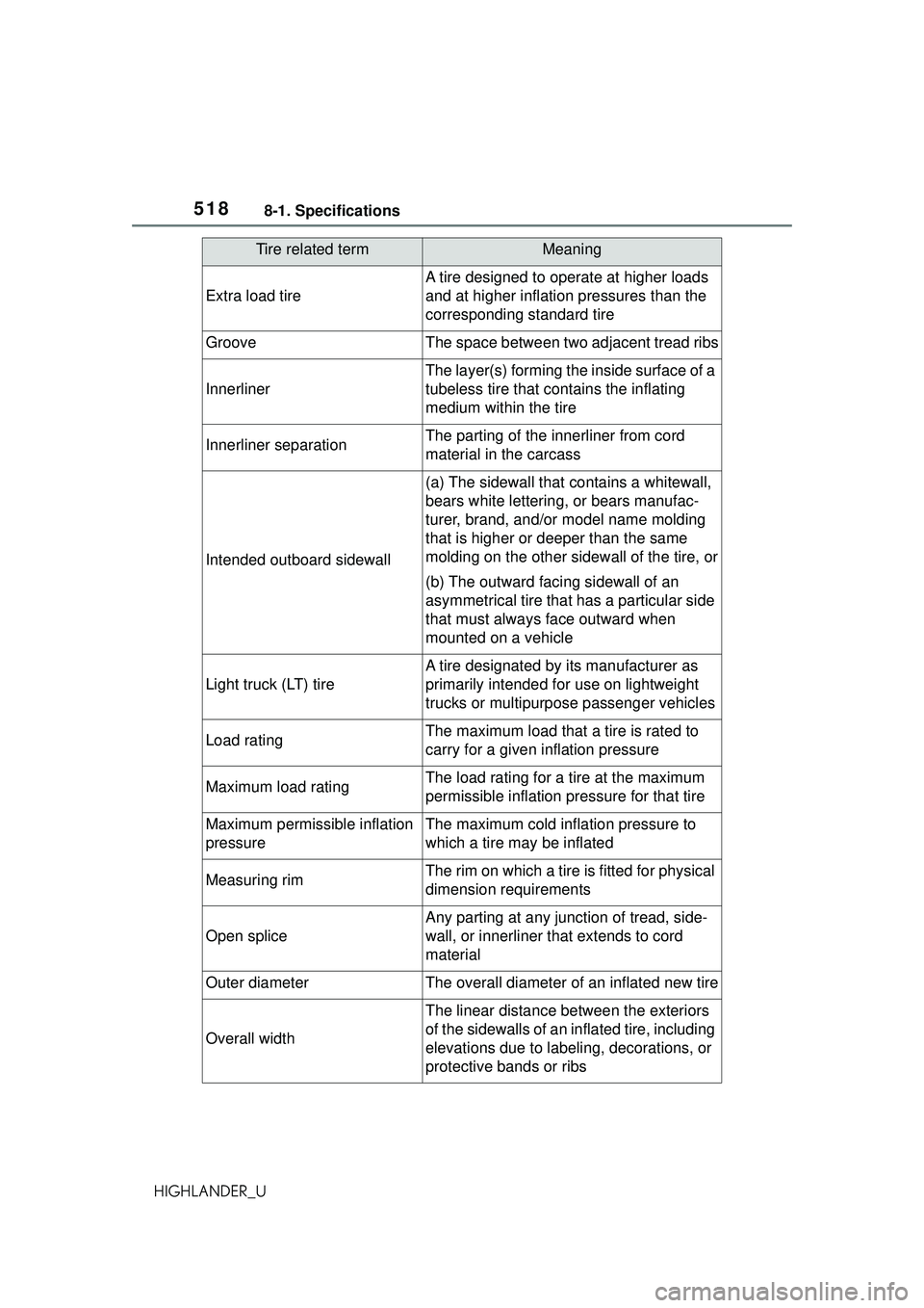
Extra load tire
A tire designed to operate at higher loads
and at higher inflation pressures than the
corresponding standard tire
GrooveThe space between two adjacent tread ribs
Innerliner
The layer(s) forming the inside surface of a
tubeless tire that contains the inflating
medium within the tire
Innerliner separationThe parting of the innerliner from cord
material in the carcass
Intended outboard sidewall
(a) The sidewall that contains a whitewall,
bears white lettering, or bears manufac-
turer, brand, and/or model name molding
that is higher or deeper than the same
molding on the other sidewall of the tire, or
(b) The outward facing sidewall of an
asymmetrical tire that has a particular side
that must always face outward when
mounted on a vehicle
Light truck (LT) tire
A tire designated by its manufacturer as
primarily intended for use on lightweight
trucks or multipurpose passenger vehicles
Load ratingThe maximum load that a tire is rated to
carry for a given inflation pressure
Maximum load ratingThe load rating for a tire at the maximum
permissible inflation pressure for that tire
Maximum permissible inflation
pressureThe maximum cold inflation pressure to
which a tire may be inflated
Measuring rimThe rim on which a tire is fitted for physical
dimension requirements
Open splice
Any parting at any junction of tread, side-
wall, or innerliner that extends to cord
material
Outer diameterThe overall diameter of an inflated new tire
Overall width
The linear distance between the exteriors
of the sidewalls of an inflated tire, including
elevations due to labeling, decorations, or
protective bands or ribs
Tire related termMeaning