ECO mode TOYOTA HIGHLANDER 2022 Owners Manual
[x] Cancel search | Manufacturer: TOYOTA, Model Year: 2022, Model line: HIGHLANDER, Model: TOYOTA HIGHLANDER 2022Pages: 568, PDF Size: 13.73 MB
Page 24 of 568
241-1. For safe use
1-1.For safe use
Use only floor mats designed
specifically for vehicles of the
same model and model year as
your vehicle. Fix them securely
in place onto the carpet.
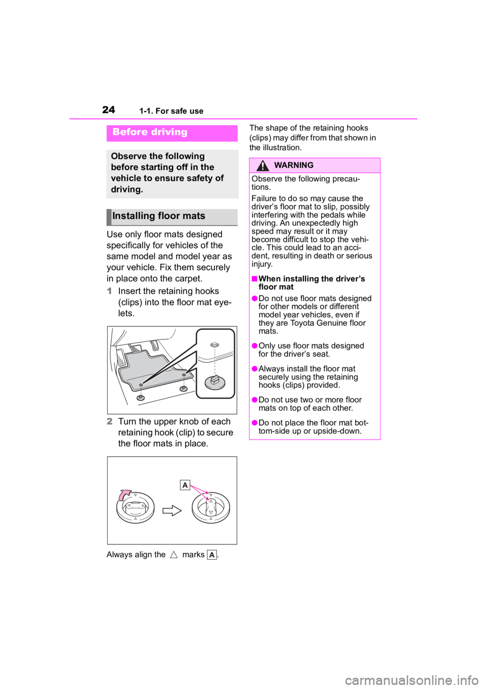
1Insert the retaining hooks
(clips) into the floor mat eye-
lets.
2 Turn the upper knob of each
retaining hook (clip) to secure
the floor mats in place.
Always align the marks . The shape of the retaining hooks
(clips) may differ from that shown in
the illustration.
Before driving
Observe the following
before starting off in the
vehicle to ensure safety of
driving.
Installing floor mats
WARNING
Observe the following precau-
tions.
Failure to do so may cause the
driver’s floor mat to slip, possibly
interfering with t
he pedals while
driving. An unexpectedly high
speed may result or it may
become difficult to stop the vehi-
cle. This could lead to an acci-
dent, resulting in death or serious
injury.
■When installing the driver’s
floor mat
●Do not use floor mats designed
for other models or different
model year vehicles, even if
they are Toyota Genuine floor
mats.
●Only use floor mats designed
for the driver’s seat.
●Always install the floor mat
securely using the retaining
hooks (clips) provided.
●Do not use two or more floor
mats on top of each other.
●Do not place the floor mat bot-
tom-side up or upside-down.
Page 53 of 568
531-2. Child safety
1
For safety and security
*: The third seats are not equipped with Child restraint LATCH anchors.
■When installing a child
restraint system to a front
passenger seatFor the safety of a child, install
child restraint systems to sec-
ond seats. When installing child
restraint system to a front pas-
senger seat is unavoidable,
adjust the seat as follows and
install the child restraint system.
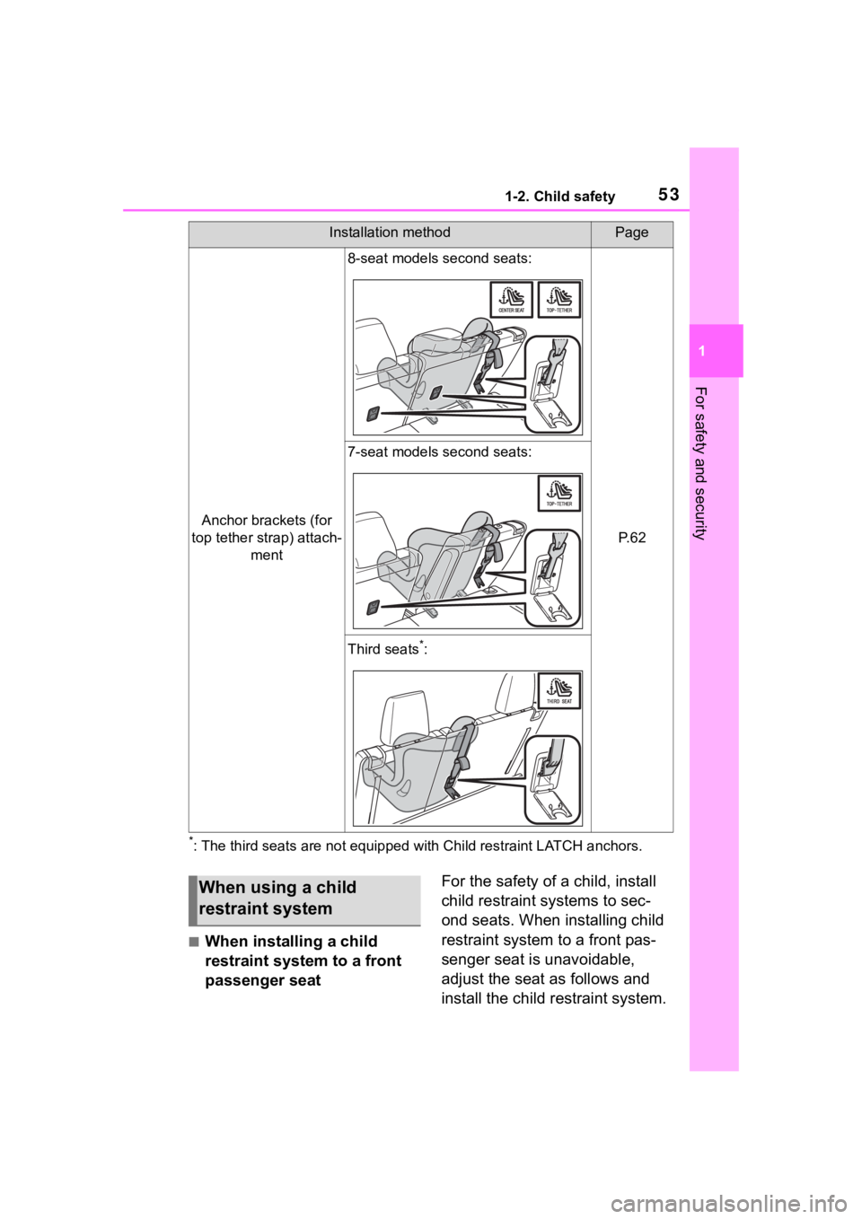
Anchor brackets (for
top tether strap) attach- ment
8-seat models second seats:
P. 6 2
7-seat models second seats:
Third seats*:
Installation methodPage
When using a child
restraint system
Page 59 of 568
591-2. Child safety
1
For safety and security
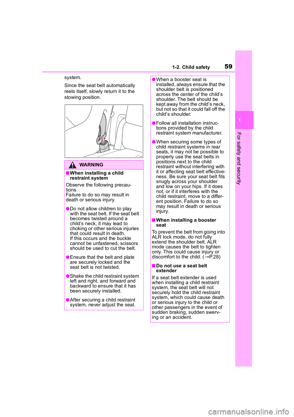
system.
Since the seat belt automatically
reels itself, slowly return it to the
stowing position.
WARNING
■When installing a child
restraint system
Observe the following precau-
tions.
Failure to do so m ay result in
death or serious injury.
●Do not allow children to play
with the seat belt. If the seat belt
becomes twisted around a
child’s neck, it may lead to
choking or other serious injuries
that could result in death.
If this occurs and the buckle
cannot be unfastened, scissors
should be used to cut the belt.
●Ensure that the belt and plate
are securely locked and the
seat belt is not twisted.
●Shake the child restraint system
left and right, and forward and
backward to ensure that it has
been securely installed.
●After securing a child restraint
system, never adjust the seat.
●When a booster seat is
installed, always ensure that the
shoulder belt is positioned
across the center of the child’s
shoulder. The belt should be
kept away from the child’s neck,
but not so that it could fall off the
child’s shoulder.
●Follow all installation instruc-
tions provided by the child
restraint system manufacturer.
●When securing some types of
child restraint systems in rear
seats, it may not be possible to
properly use the seat belts in
positions next to the child
restraint without interfering with
it or affecting seat belt effective-
ness. Be sure your seat belt fits
snugly across your shoulder
and low on your hips. If it does
not, or if it interferes with the
child restraint, move to a differ-
ent position. Fa ilure to do so
may result in death or serious
injury.
■When installing a booster
seat
To prevent the belt from going into
ALR lock mode, do not fully
extend the shoulder belt. ALR
mode causes the belt to tighten
only. This could cause injury or
discomfort to the child. ( P. 2 8 )
■Do not use a seat belt
extender
If a seat belt extender is used
when installing a child restraint
system, the seat belt will not
securely hold the child restraint
system, which could cause death
or serious injury to the child or
other passengers in the event of
sudden braking, sudden swerv-
ing or an accident.
Page 62 of 568
621-2. Child safety
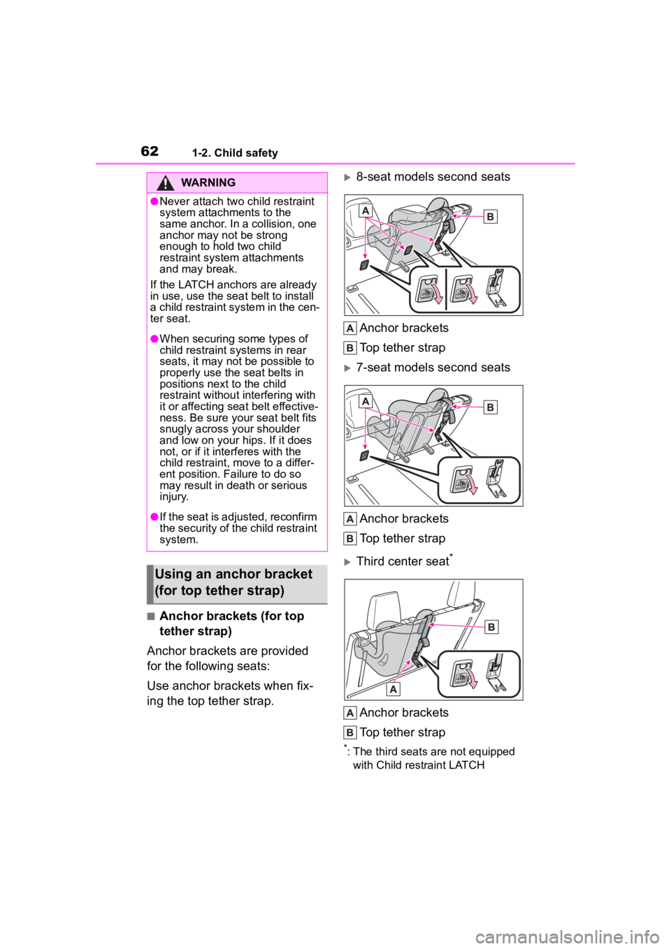
■Anchor brackets (for top
tether strap)
Anchor brackets are provided
for the following seats:
Use anchor brackets when fix-
ing the top tether strap.
8-seat models second seats
Anchor brackets
Top tether strap
7-seat models second seats
Anchor brackets
Top tether strap
Third center seat*
Anchor brackets
Top tether strap
*: The third seats are not equipped with Child restraint LATCH
WARNING
●Never attach two child restraint
system attachments to the
same anchor. In a collision, one
anchor may not be strong
enough to hold two child
restraint system attachments
and may break.
If the LATCH anchors are already
in use, use the seat belt to install
a child restraint system in the cen-
ter seat.
●When securing some types of
child restraint s ystems in rear
seats, it may not be possible to
properly use the seat belts in
positions next to the child
restraint without interfering with
it or affecting seat belt effective-
ness. Be sure your seat belt fits
snugly across your shoulder
and low on your hips. If it does
not, or if it interferes with the
child restraint, move to a differ-
ent position. Failure to do so
may result in death or serious
injury.
●If the seat is adjusted, reconfirm
the security of the child restraint
system.
Using an anchor bracket
(for top tether strap)
Page 79 of 568
792-1. Instrument cluster
2
Vehicle status information and indicators
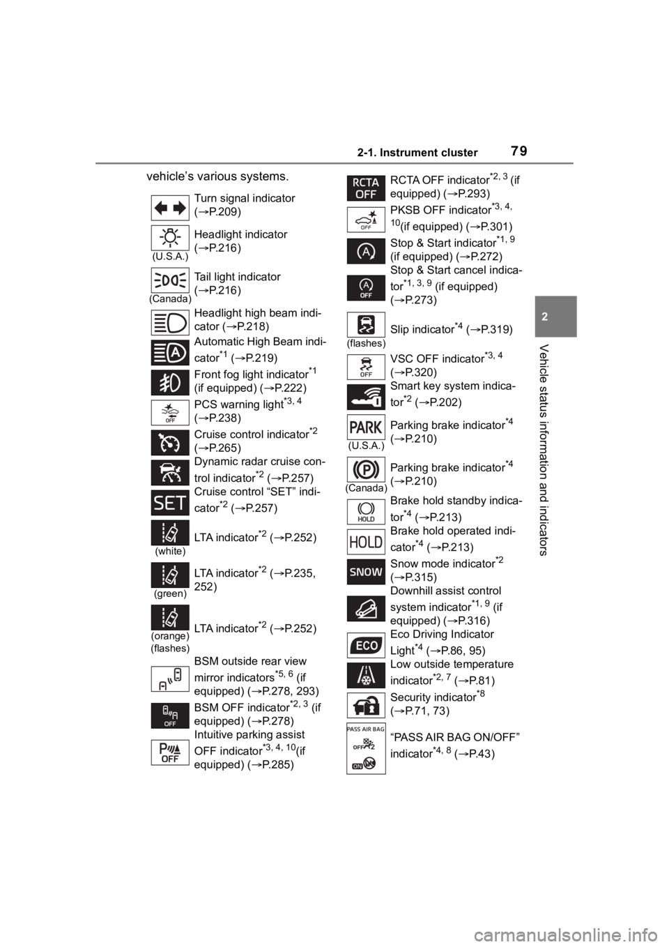
vehicle’s various systems.
Turn signal indicator
( P.209)
(U.S.A.)
Headlight indicator
( P.216)
(Canada)
Tail light indicator
( P.216)
Headlight high beam indi-
cator ( P.218)
Automatic High Beam indi-
cator
*1 ( P.219)
Front fog light indicator
*1
(if equipped) ( P.222)
PCS warning light
*3, 4
( P.238)
Cruise control indicator
*2
( P.265)
Dynamic radar cruise con-
trol indicator
*2 ( P.257)
Cruise control “SET” indi-
cator
*2 ( P.257)
(white)
LTA i n d i c a t o r*2 ( P.252)
(green)
LTA i n d i c a t o r*2 ( P.235,
252)
(orange)
(flashes)LTA i n d i c a t o r*2 ( P.252)
BSM outside rear view
mirror indicators
*5, 6 (if
equipped) (P.278, 293)
BSM OFF indicator
*2, 3 (if
equipped) (P.278)
Intuitive parking assist
OFF indicator
*3, 4, 10(if
equipped) (P.285)
RCTA OFF indicator*2, 3 (if
equipped) ( P.293)
PKSB OFF indicator
*3, 4,
10
(if equipped) ( P.301)
Stop & Start indicator
*1, 9
(if equipped) ( P.272)
Stop & Start cancel indica-
tor
*1, 3, 9 (if equipped)
( P.273)
(flashes)
Slip indicator*4 ( P.319)
VSC OFF indicator
*3, 4
( P.320)
Smart key system indica-
tor
*2 ( P.202)
(U.S.A.)
Parking brake indicator*4
( P.210)
(Canada)
Parking brake indicator*4
( P.210)
Brake hold standby indica-
tor
*4 ( P.213)
Brake hold operated indi-
cator
*4 ( P.213)
Snow mode indicator
*2
( P.315)
Downhill assist control
system indicator
*1, 9 (if
equipped) ( P.316)
Eco Driving Indicator
Light
*4 ( P. 8 6 , 9 5 )
Low outside temperature
indicator
*2, 7 ( P. 8 1 )
Security indicator
*8
( P.71, 73)
“PASS AIR BAG ON/OFF”
indicator
*4, 8 ( P. 4 3 )
Page 80 of 568
802-1. Instrument cluster
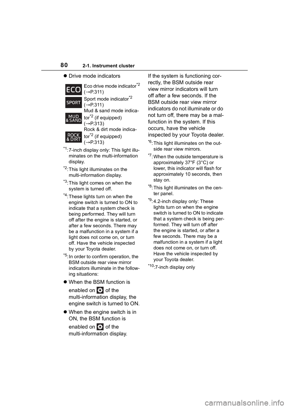
Drive mode indicators
*1: 7-inch display only: This light illu-
minates on the multi-information
display.
*2: This light illuminates on the multi-information display.
*3: This light comes on when the system is turned off.
*4: These lights turn on when the engine switch is turned to ON to
indicate that a system check is
being performed. They will turn
off after the engine is started, or
after a few seconds. There may
be a malfunction in a system if a
light does not co me on, or turn
off. Have the vehicle inspected
by your Toyota dealer.
*5: In order to confirm operation, the BSM outside rear view mirror
indicators illumina te in the follow-
ing situations:
When the BSM function is
enabled on of the
multi-information display, the
engine switch is turned to ON.
When the engine switch is in
ON, the BSM function is
enabled on of the
multi-information display. If the system is functioning cor-
rectly, the BSM outside rear
view mirror indicators will turn
off after a few seconds. If the
BSM outside rear view mirror
indicators do not illuminate or do
not turn off, there may be a mal-
function in the system. If this
occurs, have the vehicle
inspected by your Toyota dealer.
*6: This light illuminates on the out-
side rear view mirrors.
*7: When the outside temperature is approximately 37°F (3°C) or
lower, this indicator will flash for
approximately 10 seconds, then
stay on.
*8: This light illuminates on the cen-ter panel.
*9: 4.2-inch display only: These lights turn on when the engine
switch is turned to ON to indicate
that a system che ck is being per-
formed. They will turn off after
the engine is started, or after a
few seconds. There may be a
malfunction in a system if a light
does not come on, or turn off.
Have the vehicle inspected by
your Toyota dealer.
*10:7-inch display only
Eco drive mode indicator
*2
( P.311)
Sport mode indicator
*2
( P.311)
Mud & sand mode indica-
tor
*2 (if equipped)
( P.313)
Rock & dirt mode indica-
tor
*2 (if equipped)
( P.313)
Page 87 of 568
872-1. Instrument cluster
2
Vehicle status information and indicators
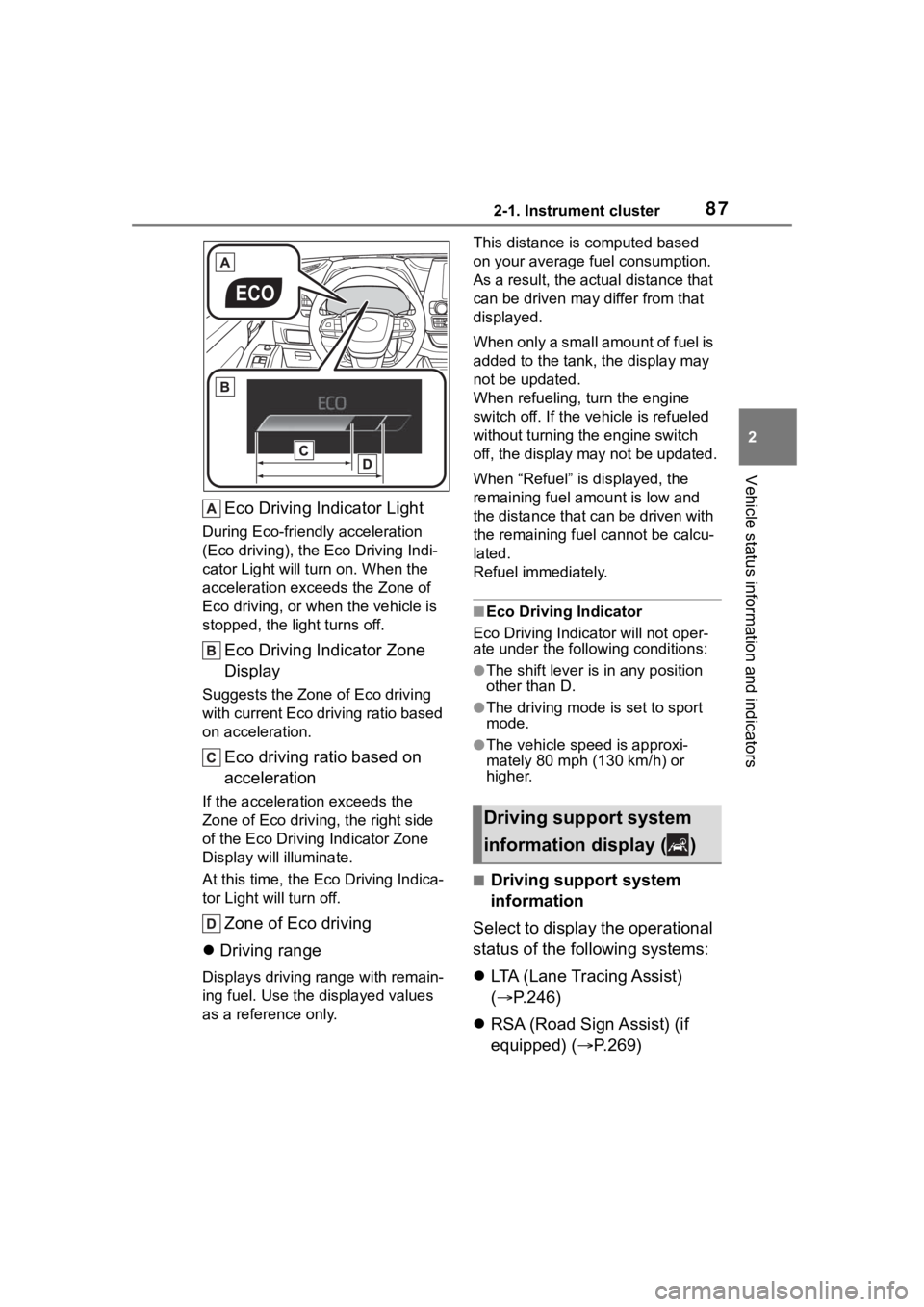
Eco Driving Indicator Light
During Eco-friendly acceleration
(Eco driving), the Eco Driving Indi-
cator Light will turn on. When the
acceleration exceeds the Zone of
Eco driving, or when the vehicle is
stopped, the light turns off.
Eco Driving Indicator Zone
Display
Suggests the Zone of Eco driving
with current Eco driving ratio based
on acceleration.
Eco driving ratio based on
acceleration
If the acceleration exceeds the
Zone of Eco driving, the right side
of the Eco Driving Indicator Zone
Display will illuminate.
At this time, the Eco Driving Indica-
tor Light will turn off.
Zone of Eco driving
Driving range
Displays driving range with remain-
ing fuel. Use the d isplayed values
as a reference only. This distance is computed based
on your average f
uel consumption.
As a result, the actual distance that
can be driven may differ from that
displayed.
When only a small amount of fuel is
added to the tank, the display may
not be updated.
When refueling, turn the engine
switch off. If the ve hicle is refueled
without turning the engine switch
off, the display may not be updated.
When “Refuel” is displayed, the
remaining fuel amount is low and
the distance that can be driven with
the remaining fuel cannot be calcu-
lated.
Refuel immediately.
■Eco Driving Indicator
Eco Driving Indicator will not oper-
ate under the following conditions:
●The shift lever is in any position
other than D.
●The driving mode is set to sport
mode.
●The vehicle spe ed is approxi-
mately 80 mph (130 km/h) or
higher.
■Driving support system
information
Select to display the operational
status of the following systems:
LTA (Lane Tracing Assist)
( P.246)
RSA (Road Sign Assist) (if
equipped) ( P.269)
Driving support system
information display ( )
Page 89 of 568
892-1. Instrument cluster
2
Vehicle status information and indicators
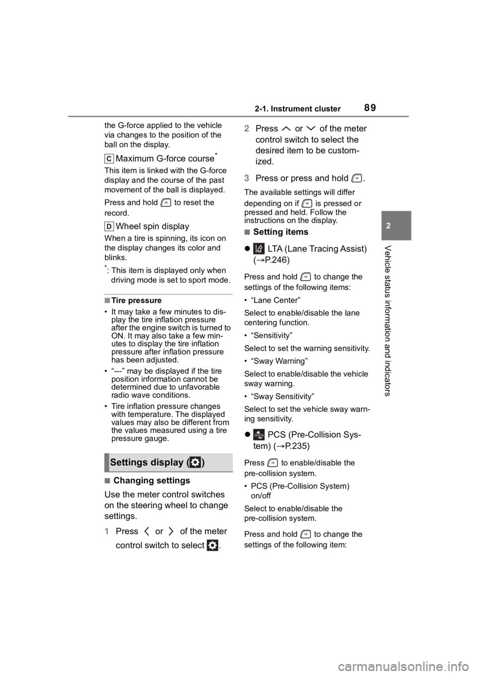
the G-force applied to the vehicle
via changes to the position of the
ball on the display.
Maximum G-force course*
This item is linke d with the G-force
display and the course of the past
movement of the ball is displayed.
Press and hold to reset the
record.
Wheel spin display
When a tire is spin ning, its icon on
the display change s its color and
blinks.
*: This item is displayed only when driving mode is set to sport mode.
■Tire pressure
• It may take a few minutes to dis- play the tire inflation pressure
after the engine switch is turned to
ON. It may also take a few min-
utes to display the tire inflation
pressure after inflation pressure
has been adjusted.
• “---” may be disp layed if the tire
position information cannot be
determined due to unfavorable
radio wave conditions.
• Tire inflation pressure changes with temperature. The displayed
values may also be different from
the values measured using a tire
pressure gauge.
■Changing settings
Use the meter control switches
on the steering wheel to change
settings.
1 Press or of the meter
control switch to select . 2
Press or of the meter
control switch to select the
desired item to be custom-
ized.
3 Press or press and hold .
The available settings will differ
depending on if is pressed or
pressed and held. Follow the
instructions on the display.
■Setting items
LTA (Lane Tracing Assist)
( P.246)
Press and hold to change the
settings of the following items:
• “Lane Center”
Select to enable /disable the lane
centering function.
• “Sensitivity”
Select to set the warning sensitivity.
• “Sway Warning”
Select to enable/disable the vehicle
sway warning.
• “Sway Sensitivity”
Select to set the vehicle sway warn-
ing sensitivity.
PCS (Pre-Collision Sys-
tem) ( P.235)
Press to enable/disable the
pre-collision system.
• PCS (Pre-Collision System)
on/off
Select to enable/disable the
pre-collision system.
Press and hold to change the
settings of the following item:Settings display ( )
Page 97 of 568
972-1. Instrument cluster
2
Vehicle status information and indicators
When “Refuel” is displayed, the
remaining fuel amount is low and
the distance that can be driven with
the remaining fuel cannot be calcu-
lated.
Refuel immediately.
■Eco Driving Indicator
Eco Driving Indica tor will not oper-
ate under the following conditions:
●The shift lever is in any position
other than D.
●The driving mode is set to sport
mode.
●The vehicle speed is approxi-
mately 80 mph (130 km/h) or
higher.
■Driving support system
information
Select to display the operational
status of the following systems:
LTA (Lane Tracing Assist)
( P.246)
RSA (Road Sign Assist) (if
equipped) ( P.269)
Dynamic radar cruise control
with full-speed range
( P.257)
■Navigation system-linked
display (if equipped)
Select to display the following
navigation system-linked infor-
mation:
Route guidance to destination
Compass display (head-
ing-up display)
■Route guidance to destination
display
When the route guidance to destina-
tion display is enabled on the
head-up display, it will not be dis-
played on the multi-information dis-
play. ( P.105)
Select to enable selection of an
audio source or track on the
meter using the meter control
switches.
This menu icon can be set to be
displayed/not displayed in .
■Tire pressure
P.420
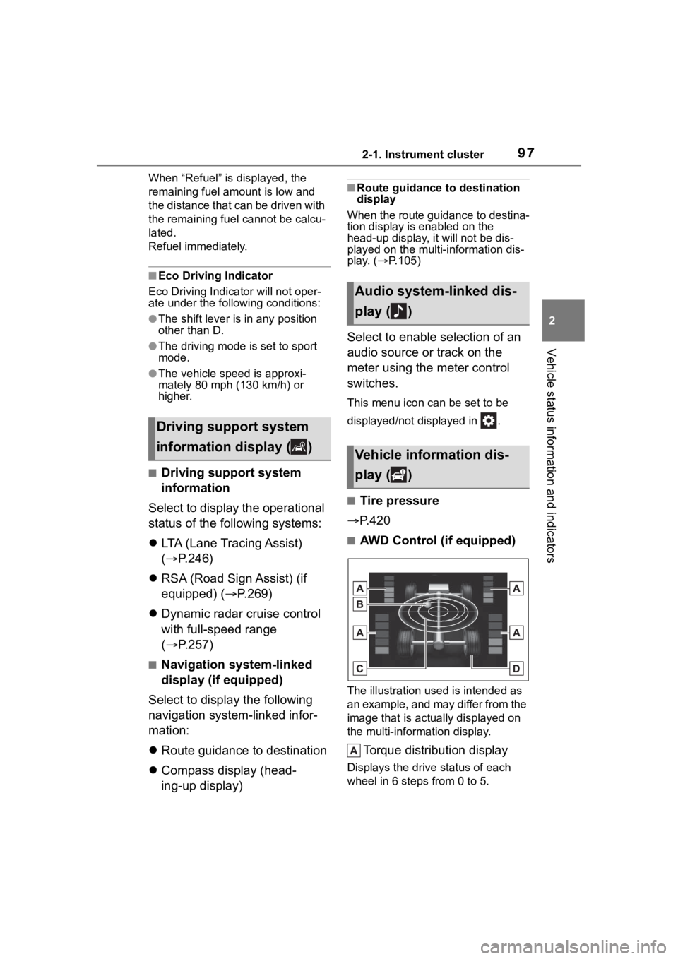
■AWD Control (if equipped)
The illustration used is intended as
an example, and may differ from the
image that is actually displayed on
the multi-information display.
Torque distribution display
Displays the drive status of each
wheel in 6 steps from 0 to 5.
Driving support system
information display ( )
Audio system-linked dis-
play ( )
Vehicle information dis-
play ( )
Page 98 of 568
982-1. Instrument cluster
G-force display*
Displays the size and direction of
the G-force applied to the vehicle
via changes to the position of the
ball on the display.
Maximum G-force course*
This item is linke d with the G-force
display and the course of the past
movement of the ball is displayed.
Press and hold to reset the
record.
Wheel spin display
When a tire is spin ning, its icon on
the display change s its color and
blinks.
*: This item is displayed only when driving mode is set to sport mode.
■Safety system status
Enable/Disable the following
systems:
PCS (Pre-Collision system)
( P.235)
Intuitive parking assist (if
equipped) ( P.284)
BSM (Blind Spot Monitor)
( P.278)
RCTA (Rear Cross Traffic
Alert) ( P.293)
■Tire pressure
• It may take a few minutes to dis- play the tire inflation pressure
after the engine switch is turned to
ON. It may also take a few min-
utes to display the tire inflation
pressure after inflation pressure
has been adjusted.
• “---” may be disp layed if the tire
position information cannot be
determined due to unfavorable radio wave conditions.
• Tire inflation pressure changes with temperature. The displayed
values may also be different from
the values measured using a tire
pressure gauge.
■Changing settings
Use the meter control switches
on the steering wheel to change
settings.
1 Press or of the meter
control switch to select .
2 Press or of the meter
control switch to select the
desired item to be custom-
ized.
3 Press or press and hold .
The available settings will differ
depending on if is pressed or
pressed and held. Follow the
instructions on the display.
■Setting items
LTA (Lane Tracing Assist)
( P.246)
Press and hold to change the
settings of the following items:
• “Lane Center”
Select to enable /disable the lane
centering function.
• “Sensitivity”
Select to set the warning sensitivity.
• “Sway Warning”
Select to enable/disable the vehicle
sway warning.
Settings display ( )