length TOYOTA HIGHLANDER 2022 Owners Manual
[x] Cancel search | Manufacturer: TOYOTA, Model Year: 2022, Model line: HIGHLANDER, Model: TOYOTA HIGHLANDER 2022Pages: 568, PDF Size: 13.73 MB
Page 91 of 568
912-1. Instrument cluster
2
Vehicle status information and indicators
Select the open position when
power back door is fully open.
•“Volume”
Select to set the volume of the
buzzer which sounds when the
power back door system operates.
(Stop & Start) (if
equipped) ( P.272)
Select to set the length of time the
Stop & Start system will operate
when the “A/C” switch of the air
conditioning system is on.
“TPWS” (Tire Pressure Warn-
ing System) ( P.420)
• “Set Pressure” (tire pressure
warning system initialization)
Select to initialize the tire pressure
warning system.
• “Change Wheel” (register tire pressure warning system sensor
ID codes)
Select to register the ID codes of
the tire pressure s ensors to the tire
pressure warning system.
“Rear Seat Reminder”
( P. 1 1 9 )
Select to enable/disable the rear
seat reminder.
“Scheduled Maintenance”
( P.401)
Select to reset the scheduled main-
tenance information (maintenance
required message and distance
until maintenance necessary) after
all maintenance is performed.
“Oil Maintenance” ( P.410)
Select to reset the oil maintenance
information (maintenance required
message and distance until mainte- nance necessary) after an oil
change is performed.
■ Meter settings
Press and hold to change
the settings of the following
items:
Language
Select to change the language dis-
played.
Units
Select to change the units of mea-
sure displayed.
Eco Driving Indicator Light
( P.86)
Select to enable/disable the Eco
Driving Indi cator Light.
Fuel economy display
Select to change the average fuel
consumption display between after
start/after reset. ( P. 8 6 )
Select to displa y/not display the
audio system linked display.
Select to change the displayed con-
tent of the following:
• Display contents
Select to displa y/not display the
AWD control (if equipped). ( P.88)
• Drive information type
Select to change the drive informa-
tion type display between after
start/after reset.
• Drive information items
Page 100 of 568
1002-1. Instrument cluster
Parking Support Brake function.
HUD (Head-up display) (if
equipped) ( P.103)
Press to enable/disable the
head-up display.
• HUD (Head-up display) on/off
Select to enable/disable the
head-up display.
Press and hold to change the
settings of the following items:
• “HUD Brightness/Position”
Select to adjust the brightness/posi-
tion of the head-up display.
• “HUD Driving Support”
Select to change the displayed
head-up display driving support
item.
• “HUD Rotation”
Select to adjust the angle of the
head-up display.
RSA (Road Sign Assist) (if
equipped) ( P.269)
Press to enable/disable the
Road Sign Assist.
• RSA (Road Sign Assist) on/off
Select to enable/disable the Road
Sign Assist.
Press and hold to change the
settings of the following items:
• “Notification Method”
Select to change e ach notification
method used to notify the driver
when the system recognizes
excess speed and no-entry sign.
• “Notification Level”
Select to change e ach notification level used to notify the driver when
the system recognizes a speed limit
sign.
■ Vehicle settings
Press and hold to change
the settings of the following
items:
PBD (Power Back Door)
( P.121)
• “System Settings”
Select to enable/disable the power
back door system.
• “Kick Sensor”
*
Select to enable/disable the kick
sensor.
• “Opening Adjustment”
Select the open position when
power back door is fully open.
•“Volume”
Select to set the volume of the
buzzer which sounds when the
power back door system operates.
*: Vehicles with a hands free power
back door
(Stop & Start) (if
equipped) ( P.272)
Select to set the length of time the
Stop & Start system will operate
when the “A/C” switch of the air
conditioning system is on.
“TPWS” (Tire Pressure Warn-
ing System) ( P.420)
• “Set Pressure” (tire pressure
warning system initialization)
Select to initialize the tire pressure
warning system.
Page 188 of 568
1884-1. Before driving
WARNING
●Even if the total load of occu-
pant’s weight and the cargo
load is less than the total load
capacity, do not apply the load
unevenly. Improper loading may
cause deteriorat ion of steering
or braking control which may
cause death or serious injury.
■When using a roof luggage
carrier (vehicles with roof
rails)
Observe the following precau-
tions:
●Place the cargo so that its
weight is distributed evenly
between the front and rear
axles.
●If loading long or wide cargo,
never exceed the vehicle overall
length or width. (
P.500)
●Before driving, make sure the
cargo is securel y fastened on
the roof luggage carrier.
●Loading cargo on the roof lug-
gage carrier will make the cen-
ter of gravity of the vehicle
higher. Avoid high speeds, sud-
den starts, sharp turns, sudden
braking or abrupt maneuvers,
otherwise it may result in loss of
control or vehicle rollover due to
failure to operate this vehicle
correctly and resu lt in death or
serious injury.
●If driving for a long distance, on
rough roads, or at high speeds,
stop the vehicle now and then
during the trip to make sure the
cargo remains in its place.
●Do not exceed 165 lb. (75 kg)
cargo weight on the roof lug-
gage carrier.
NOTICE
■When loading cargo
Be careful not to scratch the sur-
face of the moon roof or pan-
oramic moon roof.
Page 197 of 568
1974-1. Before driving
4
Driving
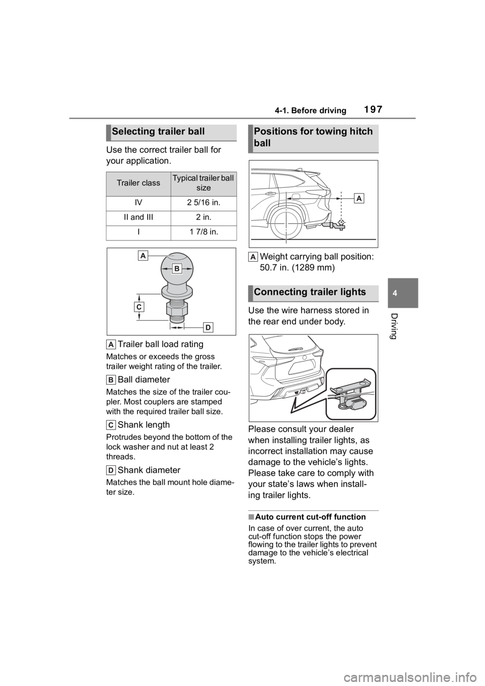
Use the correct trailer ball for
your application.Trailer ball load rating
Matches or exceeds the gross
trailer weight rat ing of the trailer.
Ball diameter
Matches the size of the trailer cou-
pler. Most couplers are stamped
with the required tr ailer ball size.
Shank length
Protrudes beyond the bottom of the
lock washer and nut at least 2
threads.
Shank diameter
Matches the ball mount hole diame-
ter size.
Weight carrying ball position:
50.7 in. (1289 mm)
Use the wire harness stored in
the rear end under body.
Please consult your dealer
when installing trailer lights, as
incorrect installation may cause
damage to the vehicle’s lights.
Please take care to comply with
your state’s laws when install-
ing trailer lights.
■Auto current cut-off function
In case of over current, the auto
cut-off function stops the power
flowing to the trailer lights to prevent
damage to the vehicle’s electrical
system.
Selecting trailer ball
Trailer classTypical trailer ball size
IV2 5/16 in.
II and III2 in.
I1 7/8 in.
Positions for towing hitch
ball
Connecting trailer lights
Page 199 of 568

1994-1. Before driving
4
Driving
requires practice. Grip the
bottom of the steering wheel
and move your hand to the
left to move the trailer to the
left. Move your hand to the
right to move the trailer to
right. (This is generally oppo-
site to reversing without a
trailer attached.) Avoid sharp
or prolonged turning. Have
someone guide you when
reversing to reduce the risk of
an accident.
As stopping distance is
increased when towing a
trailer, vehicle-to vehicle dis-
tance should be increased.
For each 10 mph (16 km/h) of
speed, allow at least one
vehicle and trailer length.
Avoid sudden braking as you
may skid, resulting in the
trailer jackknifing and a loss of
vehicle control. This is espe-
cially true on wet or slippery
surfaces.
Avoid jerky starts or sudden
acceleration.
Avoid jerky steering and
sharp turns, and slow down
before making turn.
Note that when making a turn,
the trailer wheels will be
closer than the vehicle wheels
to the inside of the turn. Com-
pensate by making a wider
than normal turning radius.
Slow down before making a turn, in cross winds, on wet or
slippery surfaces, etc.
Increasing vehicle speed can
destabilize the trailer.
Take care when passing other
vehicles. Passing requires
considerable distance. After
passing a vehicle, do not for-
get the length of your trailer,
and be sure you have plenty
of room before changing
lanes.
To maintain engine braking
efficiency and charging sys-
tem performance when using
engine braking, do not put the
transmission in D. If in the M
mode, the transmission shift
range position must be in 6 or
lower. ( P.206)
Instability happens more fre-
quently when descending
steep or long downhill grades.
Before descending, slow
down and downshift. Do not
make sudden downshifts
while descending steep or
long downhill grades.
Avoid holding the brake pedal
down too long or applying the
brakes too frequently. This
could cause the brakes to
overheat and result in
reduced braking efficiency.
Due to the added load of the
trailer, your vehicle’s engine
may overheat on hot days (at
temperatures over 85°F
[30°C]) when driving up a long
Page 275 of 568
2754-5. Using the driving support systems
4
Driving
in the following situations: (To
enable the engine to be stopped
by the Stop & Start system again,
drive the vehicle.)
• When the brake pedal is pumped or strongly depressed.
• When the air conditioning system is being used.
• When a switch of the air condition-
ing system is operated (windshield
defogger switch, etc.).
• If the battery charge becomes low.
■When the hood is opened
●If the hood is opened while the
engine is stopped by the Stop &
Start system, the engine will stall
and will not be able to be restarted
by the automatic engine start
function. In this case, restart the
engine using the normal engine
starting procedure. ( P.202)
●If the hood is closed after the
engine is started with the hood
open, the Stop & Start system will
not operate. Close the hood, turn
the engine switch off, wait 30 sec-
onds or more, and then start the
engine.
■Air conditioning system opera-
tion while the engine is stopped
by the Stop & Start system
Vehicles with an automatic air con-
ditioning system: When the air con-
ditioning is in automatic mode and
the engine is stopped by the Stop &
Start system, the fan may operate at
a low speed in order to prevent the
temperature in the cabin from
increasing or decreasing or may be
stopped.
To prioritize air conditioning system
performance when the vehicle is
stopped, disable the Stop & Start
system by pressing the Stop & Start
cancel switch.
●If the windshield is fogged up
Turn the windshield defogger on.
( P.339)
If the windshield fogs up frequently,
press the Stop & Start cancel switch to disable the Stop & Start system.
●If an odor is emitted from the air
conditioning system
• Vehicles with a manual air condi- tioning system
If the idling stop time setting is set to
“Extended” change it to “Standard”.
If an odor is emitted when the idling
stop time setting is set to “Stan-
dard”, press the Stop & Start cancel
switch to deactivate the Stop & Start
system.
• Vehicles with a n automatic air
conditioning system
Press the Stop & Start cancel switch
to deactivate the Stop & Start sys-
tem.
■Changing the idling stop time
with the air conditioning system
on
The length of time the Stop & Start
system will operate when the air
conditioning system is on can be
changed in of th e multi-informa-
tion display ( P.89, 98). (The length
of time the Stop & Start system will
operate when the a ir conditioning
system is off cann ot be changed.)
■Displaying the Stop & Start sys-
tem status
P.89, 98
■Multi-information display mes-
sages
If the following situations, and a
message may be displayed on the
multi-information display.
●When the engine cannot be
stopped by the Stop & Start sys-
tem “Press brake mo re to activate”
• The brake pedal is not sufficiently depressed.
If the brake pedal is depressed
further, the system will operate.
Page 326 of 568
![TOYOTA HIGHLANDER 2022 Owners Manual 3264-6. Driving tips
Side chain (0.12 in. [3 mm] in
diameter)
Side chain (0.39 in. [10 mm]
in width)
Side chain (1.18 in. [30 mm]
in length)
Cross chain (0.16 in. [4 mm]
in diameter)
Cross chain ( TOYOTA HIGHLANDER 2022 Owners Manual 3264-6. Driving tips
Side chain (0.12 in. [3 mm] in
diameter)
Side chain (0.39 in. [10 mm]
in width)
Side chain (1.18 in. [30 mm]
in length)
Cross chain (0.16 in. [4 mm]
in diameter)
Cross chain (](/img/14/59254/w960_59254-325.png)
3264-6. Driving tips
Side chain (0.12 in. [3 mm] in
diameter)
Side chain (0.39 in. [10 mm]
in width)
Side chain (1.18 in. [30 mm]
in length)
Cross chain (0.16 in. [4 mm]
in diameter)
Cross chain (0.55 in. [14 mm]
in width)
Cross chain (0.98 in. [25 mm]
in length)
Regulations regarding the use
of tire chains vary depending on
location and type of road.
Always check local regulations
before installing chains.
■Tire chain installation
Observe the following precautions
when installing and removing
chains:
●Install and remove tire chains in a
safe location.
●Install tire chains on the front tires
only. Do not install tire chains on
the rear tires.
●Install tire chains on front tires as
tightly as possible. Retighten
chains after driving 1/4 1/2 mile
(0.5 1.0 km).
●Install tire chains following the
instructions provi ded with the tire
chains.
Regulations on the use of
tire chains
NOTICE
■Fitting tire chains
The tire pressure warning valves
and transmitters may not function
correctly when tire chains are fit-
ted.
Page 500 of 568
5008-1. Specifications
8-1.Specifications
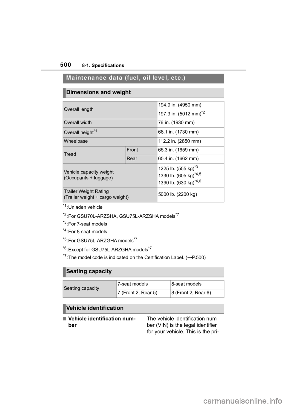
*1: Unladen vehicle
*2: For GSU70L-ARZSHA, GSU75L-ARZSHA models*7
*3
: For 7-seat models
*4: For 8-seat models
*5: For GSU75L-ARZGHA models*7
*6
: Except for GSU75L-ARZGHA models*7
*7
: The model code is indicated o n the Certification Label. (P.500)
■Vehicle identification num-
ber The vehicle identification num-
ber (VIN) is the legal identifier
for your vehicle. This is the pri-
Maintenance data (fuel, oil level, etc.)
Dimensions and weight
Overall length194.9 in. (4950 mm)
197.3 in. (5012 mm)
*2
Overall width76 in. (1930 mm)
Overall height*168.1 in. (1730 mm)
Wheelbase112.2 in. (2850 mm)
TreadFront65.3 in. (1659 mm)
Rear65.4 in. (1662 mm)
Vehicle capacity weight
(Occupants + luggage)1225 lb. (555 kg)*3
1330 lb. (605 kg)*4,5
1390 lb. (630 kg)*4,6
Trailer Weight Rating
(Trailer weight + cargo weight)5000 lb. (2200 kg)
Seating capacity
Seating capacity7-seat models8-seat models
7 (Front 2, Rear 5)8 (Front 2, Rear 6)
Vehicle identification