start stop button TOYOTA HIGHLANDER 2022 Owners Manual
[x] Cancel search | Manufacturer: TOYOTA, Model Year: 2022, Model line: HIGHLANDER, Model: TOYOTA HIGHLANDER 2022Pages: 568, PDF Size: 13.73 MB
Page 135 of 568

1353-2. Opening, closing and locking the doors
3
Before driving
wireless remote control or the
mechanical key, to unlock the
doors.
■Turning an electronic key to
battery-saving mode
When battery-savi ng mode is set,
battery depletion is minimized by
stopping the electronic key from
receiving radio waves.
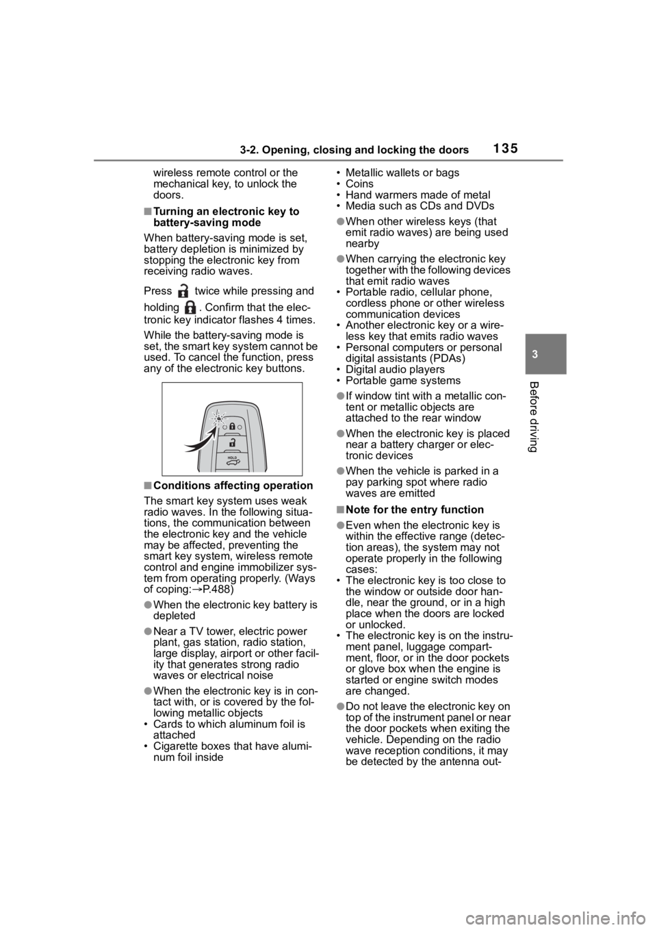
Press twice while pressing and
holding . Confirm that the elec-
tronic key indicator flashes 4 times.
While the battery-saving mode is
set, the smart key system cannot be
used. To cancel the function, press
any of the electronic key buttons.
■Conditions affecting operation
The smart key system uses weak
radio waves. In the following situa-
tions, the communication between
the electronic key and the vehicle
may be affected, preventing the
smart key system, wireless remote
control and engine immobilizer sys-
tem from operating properly. (Ways
of coping: P.488)
●When the electronic key battery is
depleted
●Near a TV tower, electric power
plant, gas station , radio station,
large display, airpo rt or other facil-
ity that generates strong radio
waves or electrical noise
●When the electronic key is in con-
tact with, or is covered by the fol-
lowing metallic objects
• Cards to which al uminum foil is
attached
• Cigarette boxes that have alumi- num foil inside • Metallic wallets or bags
•Coins
• Hand warmers made of metal
• Media such as CDs and DVDs
●When other wirel
ess keys (that
emit radio waves) are being used
nearby
●When carrying the electronic key
together with the following devices
that emit radio waves
• Portable radio, cellular phone, cordless phone or other wireless
communication devices
• Another electronic key or a wire- less key that emits radio waves
• Personal computers or personal
digital assistants (PDAs)
• Digital audio players
• Portable game systems
●If window tint wit h a metallic con-
tent or metallic objects are
attached to the rear window
●When the electronic key is placed
near a battery charger or elec-
tronic devices
●When the vehicle is parked in a
pay parking spot where radio
waves are emitted
■Note for the entry function
●Even when the electronic key is
within the effective range (detec-
tion areas), the system may not
operate properly in the following
cases:
• The electronic key is too close to the window or outside door han-
dle, near the ground, or in a high
place when the doors are locked
or unlocked.
• The electronic key is on the instru-
ment panel, luggage compart-
ment, floor, or in the door pockets
or glove box when the engine is
started or engine switch modes
are changed.
●Do not leave the electronic key on
top of the instrument panel or near
the door pockets when exiting the
vehicle. Depending on the radio
wave reception conditions, it may
be detected by the antenna out-
Page 207 of 568

2074-2. Driving procedures
4
Driving
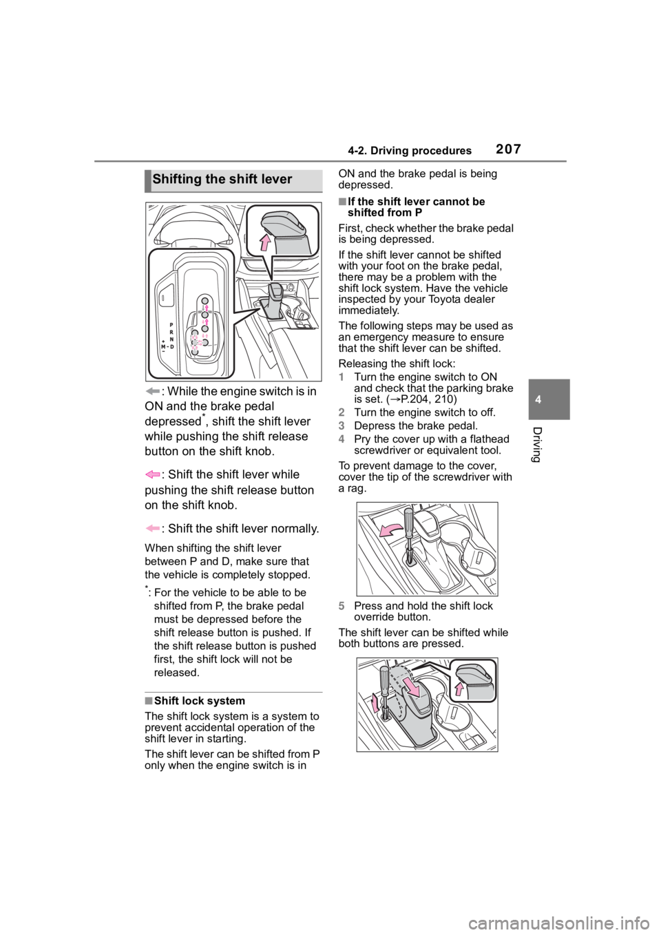
: While the engine switch is in
ON and the brake pedal
depressed
*, shift the shift lever
while pushing the shift release
button on the shift knob.
: Shift the shift lever while
pushing the shift release button
on the shift knob.
: Shift the shift lever normally.
When shifting the shift lever
between P and D, make sure that
the vehicle is completely stopped.
*: For the vehicle to be able to be
shifted from P, the brake pedal
must be depresse d before the
shift release button is pushed. If
the shift release button is pushed
first, the shift lock will not be
released.
■Shift lock system
The shift lock system is a system to
prevent accidental operation of the
shift lever in starting.
The shift lever can be shifted from P
only when the engine switch is in ON and the brake pedal is being
depressed.
■If the shift lever cannot be
shifted from P
First, check whether the brake pedal
is being depressed.
If the shift lever cannot be shifted
with your foot on the brake pedal,
there may be a p roblem with the
shift lock system. Have the vehicle
inspected by your Toyota dealer
immediately.
The following steps may be used as
an emergency measure to ensure
that the shift lev er can be shifted.
Releasing the shift lock:
1 Turn the engine switch to ON
and check that the parking brake
is set. ( P.204, 210)
2 Turn the engine switch to off.
3 Depress the brake pedal.
4 Pry the cover up with a flathead
screwdriver or equivalent tool.
To prevent damag e to the cover,
cover the tip of the screwdriver with
a rag.
5 Press and hold the shift lock
override button.
The shift lever can be shifted while
both buttons are pressed.
Shifting the shift lever
Page 214 of 568

2144-2. Driving procedures
●The parking brake is engaged.
If any of the conditions above are
detected when the brake hold sys-
tem is enabled, the system will turn
off and the brake hold standby indi-
cator light will go of f. In addition, if
any of the conditions are detected
while the system is holding the
brake, a warning buzzer will sound
and a message will be shown on the
multi-information display. The park-
ing brake will then be set automati-
cally.
■Brake hold function
●If the brake pedal is left released
for a period of about 3 minutes
after the system has started hold-
ing the brake, the parking brake
will be set automatically. In this
case, a warning buzzer sounds
and a message is shown on the
multi-informat ion display.
●To turn the system off while the
system is holding the brake, firmly
depress the brake pedal and
press the button again.
●The brake hold function may not
hold the vehicle when the vehicle
is on a steep inclin e. In this situa-
tion, it may be necessary for the
driver to apply the brakes. A warn-
ing buzzer will sound and the
multi-informatio n display will
inform the driver of this situation. If
a warning message is shown on
the multi-information display, read
the message and follow the
instructions.
■When the parking brake is set
automatically while the system
is holding the brakes
Perform any of the following opera-
tions to release the parking brake.
●Depress the accelerator pedal.
(The parking brake will not be
released automatic ally if the seat
belt is not fastened.)
●Operate the parking brake switch
with the brake pedal depressed.
Make sure that the parking brake indicator light goes off. (
P.210)
■When an inspection at your
Toyota dealer is necessary
When the brake hold standby indi-
cator (green) does not illuminate
even when the brake hold switch is
pressed with the brake hold system
operating conditions met, the sys-
tem may be malf unctioning. Have
the vehicle inspected at your Toyota
dealer.
■If “Brake Hold Malfunction
Press Brake to Deactivate Visit
Your Dealer” or “Brake Hold
Malfunction Visit Your Dealer”
is displayed on the multi-infor-
mation display
The system may be malfunctioning.
Have the vehicle inspected by your
Toyota dealer.
■Warning messages and buzzers
Warning messages and buzzers are
used to indicate a system malfunc-
tion or to inform the driver of the
need for caution. If a warning mes-
sage is shown on the multi-informa-
tion display, read the message and
follow the instructions.
■If the brake hold operated indi-
cator flashes
P.463
WARNING
■When the vehicle is on a
steep incline
When using the br ake hold sys-
tem on a steep incline, exercise
caution. The brake hold function
may not hold the vehicle in such a
situation.
■When stopped on a slippery
road
The system cannot stop the vehi-
cle when the gripping ability of the
tires has been exceeded. Do not
use the system w hen stopped on
a slippery road.
Page 390 of 568

3905-5. Using the other interior features
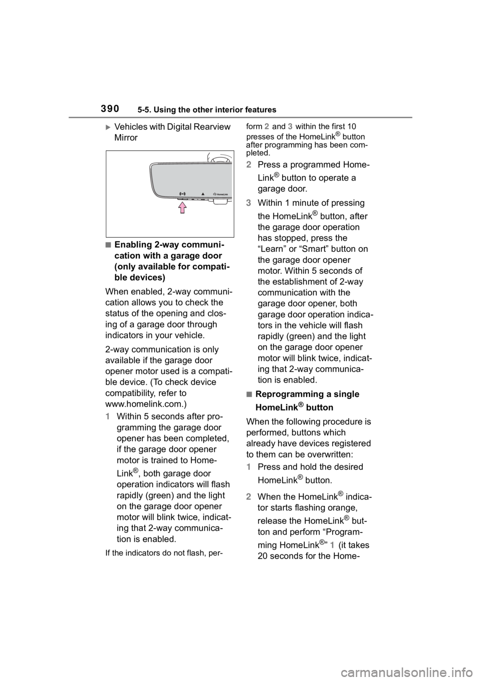
Vehicles with Digital Rearview
Mirror
■Enabling 2-way communi-
cation with a garage door
(only available for compati-
ble devices)
When enabled, 2-way communi-
cation allows you to check the
status of the opening and clos-
ing of a garage door through
indicators in your vehicle.
2-way communication is only
available if the garage door
opener motor used is a compati-
ble device. (To check device
compatibility, refer to
www.homelink.com.)
1 Within 5 seconds after pro-
gramming the garage door
opener has been completed,
if the garage door opener
motor is trained to Home-
Link
®, both garage door
operation indicators will flash
rapidly (green) and the light
on the garage door opener
motor will blink twice, indicat-
ing that 2-way communica-
tion is enabled.
If the indicators do not flash, per- form
2 and 3 within the first 10
presses of the HomeLink
® button
after programming has been com-
pleted.
2 Press a programmed Home-
Link
® button to operate a
garage door.
3 Within 1 minute of pressing
the HomeLink
® button, after
the garage door operation
has stopped, press the
“Learn” or “Smart” button on
the garage door opener
motor. Within 5 seconds of
the establishment of 2-way
communication with the
garage door opener, both
garage door operation indica-
tors in the vehicle will flash
rapidly (green) and the light
on the garage door opener
motor will blink twice, indicat-
ing that 2-way communica-
tion is enabled.
■Reprogramming a single
HomeLink
® button
When the following procedure is
performed, buttons which
already have devices registered
to them can be overwritten:
1 Press and hold the desired
HomeLink
® button.
2 When the HomeLink
® indica-
tor starts flashing orange,
release the HomeLink
® but-
ton and perform “Program-
ming HomeLink
®” 1 (it takes
20 seconds for the Home-
Page 561 of 568

561Alphabetical Index
Sun visors ............................... 383
SunshadeRoof...................................... 170
Switches Activating the Automatic High Beam .................................. 219
Automatic High Beam system ........................................... 219
Brake Hold switch ................ 213
Digital Rearview Mirror control switches ............................. 155
Door lock switches ............... 120
Driving mode select switch... 311
Driving position memory switches ............................. 147
Dynamic radar cruise control with full-speed range switch257
Electronic roof sunshade switches ............................. 173
Emergency flashers switch .. 448
Engine switch ....................... 202
Fog light switch .................... 222
Garage door opener switches ........................................... 385
Heated steering wheel switch ........................................... 358
Ignition switch....................... 202
Instrument panel light control switches ............................... 83
Intuitive parking assist switch285
Light switches....................... 216
LTA (Lane Tracing Assist) switch ........................................... 252
Meter control switches ..... 85, 94
Moon roof switches .............. 170
“ODO TRIP” switch ................ 83
Outside rear view mirror switches ............................. 165
Panoramic moon roof switches ........................................... 173
Parking brake switch ............ 210
PCS OFF switch................... 238 PKSB (Parking Support Brake)
switch .................................301
Power door lock switch.........120
Power window switches .......167
RCTA switch .........................294
Rear window and outside rear view mirror defoggers switch...........................335, 341, 345
Seat heater switches ............358
Seat ventilator switches........358
Snow mode switch ...............315
“SOS” button ..........................65
Stop & Start cancel switch ....273
Tilt and telescopic steering con- trol switch ...........................153
Tire pressure warning reset switch .................................424
Vehicle-to-vehicle distance switch .................................257
VSC OFF switch ...................319
Window lock switch ..............169
Windshield defogger switch 335, 341, 344
Windshield wiper and washer switch .........................222, 225
Windshield wiper de-icer switch ...........................336, 341, 349
T
Tachometer ...............................81
Tail lights Light switch...........................216
Replacing light bulbs ............439
The Secondary Collision Brake ...............................................319
Theft deterrent system Alarm ......................................73
Engine immobilizer system .....71
Tire inflation pressure Maintenance data .................505
Tire inflation pressure display function ...............................420