warning TOYOTA HIGHLANDER 2023 Owners Manual
[x] Cancel search | Manufacturer: TOYOTA, Model Year: 2023, Model line: HIGHLANDER, Model: TOYOTA HIGHLANDER 2023Pages: 552, PDF Size: 13.36 MB
Page 446 of 552
4467-2. Steps to take in an emergency
• “Oil Pressure Low Stop in a Safe
Place See Owner's Manual”
• “Charging System Malfunction
Stop in a Safe Place See Owner's
Manual”
●If “Smart Key System Malfunction
See Owner's Manual” is shown on
the multi-information display, it
may indicate a malfunction. Have
the vehicle inspected by your Toy-
ota dealer immediately.
●If any of the following messages
are shown on the multi-informa-
tion display, follow the instruc-
tions.
• “Engine Coolant Temp High Stop
in a Safe Place See Owner's Man-
ual” ( P.469)
• “High Transmission Fluid Temp
See Owner's Manual” ( P.201)
Stop the vehicle in a safe
place on a hard, flat surface.
Set the parking brake.
Shift the shift lever to P.
Stop the engine.
Turn on the emergency flash-
ers. ( P.424)
For vehicles with power back
door: Turn off the power back
door system. ( P.494)
NOTICE
■If “High Power Consumption
Partial Limit on AC/Heater
Operation” is displayed fre-
quently
There is a possible malfunction
relating to the charging system or
the battery may be deteriorating.
Have the vehicle inspected by
your Toyota dealer.
If you have a flat tire
Your vehicle is equipped
with a spare tire. The flat tire
can be replaced with the
spare tire.
For details about tires:
P.393
WARNING
■If you have a flat tire
Do not continue driving with a flat
tire.
Driving even a short distance with
a flat tire can damage the tire and
the wheel beyond repair, which
could result in an accident.
Before jacking up the
vehicle
Page 447 of 552
4477-2. Steps to take in an emergency
7
When trouble arises
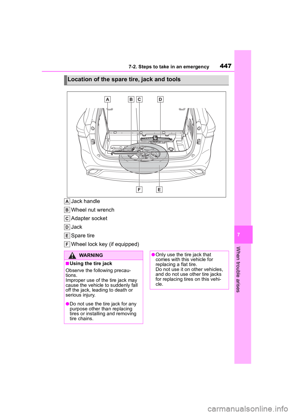
Jack handle
Wheel nut wrench
Adapter socket
Jack
Spare tire
Wheel lock key (if equipped)
Location of the spare tire, jack and tools
WARNING
■Using the tire jack
Observe the following precau-
tions.
Improper use of the tire jack may
cause the vehicle to suddenly fall
off the jack, leading to death or
serious injury.
●Do not use the tire jack for any
purpose other than replacing
tires or installing and removing
tire chains.
●Only use the tire jack that
comes with this vehicle for
replacing a flat tire.
Do not use it on other vehicles,
and do not use other tire jacks
for replacing tires on this vehi-
cle.
Page 448 of 552
4487-2. Steps to take in an emergency
When replacing tires on a vehi-
cle with wheel lock nuts, use the
following procedures to remove
and install the wheel lock nuts.
The wheel lock key is stored in
the tray inside the luggage com- partment. Always return the
wheel lock key to its original
position after use, so that it does
not get lost. (
P.447)
■Removal
For ease of removal, the wheel
lock nut should always be the
first one loosened.
1 Place the wheel lock key on
top of the wheel lock nut,
turning until the wheel lock
key and wheel lock nut pat-
terns engage.
2 Place the wheel nut wrench
on the wheel lock key, and
while applying pressure on
the wheel lock key, loosen
the wheel lock nut.
■Installation
For ease of installation, the
wheel lock nut should always be
the last one tightened.
1 By hand, install a wheel lock
nut on each wheel.
2 Place the wheel lock key on
top of the wheel lock nut,
turning until the wheel lock
key and wheel lock nut pat-
terns engage.
3 Place the wheel nut wrench
on the wheel lock key, and
while applying pressure on
the wheel lock key, tighten
the wheel lock nut to the rec-
ommended torque.
WARNING
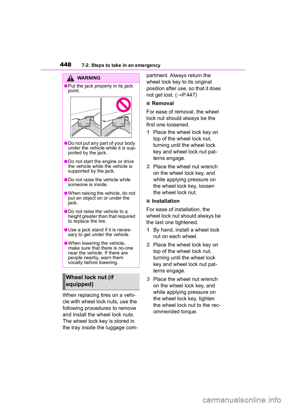
●Put the jack prope rly in its jack
point.
●Do not put any part of your body
under the vehicle while it is sup-
ported by the jack.
●Do not start the engine or drive
the vehicle while the vehicle is
supported by the jack.
●Do not raise the vehicle while
someone is inside.
●When raising the vehicle, do not
put an object on or under the
jack.
●Do not raise the vehicle to a
height greater than that required
to replace the tire.
●Use a jack stand if it is neces-
sary to get under the vehicle.
●When lowering the vehicle,
make sure that there is no-one
near the vehicle. If there are
people nearby, warn them
vocally before lowering.
Wheel lock nut (if
equipped)
Page 452 of 552
4527-2. Steps to take in an emergency
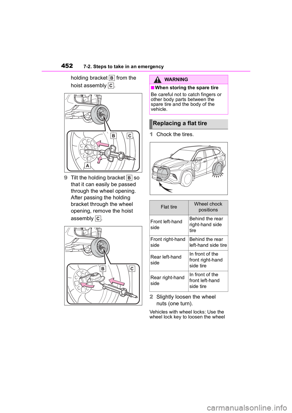
holding bracket from the
hoist assembly .
9 Tilt the holding bracket so
that it can easily be passed
through the wheel opening.
After passing the holding
bracket through the wheel
opening, remove the hoist
assembly . 1
Chock the tires.
2 Slightly loosen the wheel
nuts (one turn).
Vehicles with wheel locks: Use the
wheel lock key to loosen the wheel
WARNING
■When storing the spare tire
Be careful not to catch fingers or
other body parts between the
spare tire and the body of the
vehicle.
Replacing a flat tire
Flat tireWheel chock
positions
Front left-hand
sideBehind the rear
right-hand side
tire
Front right-hand
sideBehind the rear
left-hand side tire
Rear left-hand
sideIn front of the
front right-hand
side tire
Rear right-hand
sideIn front of the
front left-hand
side tire
Page 454 of 552
4547-2. Steps to take in an emergency
ered, the wire cable may be sev-
ered. Have the vehicle inspected by
your Toyota dealer.
1Remove any dirt or foreign
matter from the wheel con-
tact surface.
If foreign matter is on the wheel
contact surface, the wheel nuts
may loosen while the vehicle is in
WARNING
■Replacing a flat tire
●Do not touch the disc wheels or
the area around the brakes
immediately after the vehicle
has been driven.
After the vehicle has been
driven the disc wheels and the
area around the brakes will be
extremely hot. Touching these
areas with hands , feet or other
body parts while changing a tire,
etc. may result in burns.
●Failure to follow these precau-
tions could cause the wheel
nuts to loosen and the tire to fall
off, resulting in death or serious
injury.
• Never use oil or grease on the wheel bolts or wheel nuts.
Oil and grease may cause the
wheel nuts to be excessively
tightened, leading to bolt or disc
wheel damage. In addition, the
oil or grease can cause the
wheel nuts to loosen and the
wheel may fall off, causing an
accident and resulting in death
or serious injury. Remove any
oil or grease from the wheel
bolts or wheel nuts.
• Have the wheel nuts tightened with a torque wrench to 76 ft•lbf
(103 N•m, 10.5 kgf•m) as soon
as possible after changing
wheels.
• When installing a tire, only use wheel nuts that have been spe-
cifically designed for that wheel.
• If there are any cracks or defor- mations in the bolt screws, nut
threads or bolt holes of the
wheel, have the vehicle
inspected by your Toyota
dealer.
• Do not attach a heavily dam- aged wheel ornament, as it may
fly off the wheel while the vehi-
cle is moving.
●Observe the fo llowing precau-
tions.
Failure to do so may result in
serious injury:
• Do not try to remove the wheel ornament by hand. Take due
care in handling the ornament to
avoid unexpected personal
injury.
• Lower the spare tire completely to the ground before removing it
from under the vehicle.
■Replacing a flat tire for vehi-
cles with power back door
In cases such as when replacing
tires, make sure to turn off the
power back door main switch
( P.494). Failure to do so may
cause the back d oor to operate
unintentionally if the power back
door switch is accidentally
touched, resulti ng in hands and
fingers being caught and injured.
Installing the spare tire
Page 455 of 552
4557-2. Steps to take in an emergency
7
When trouble arises
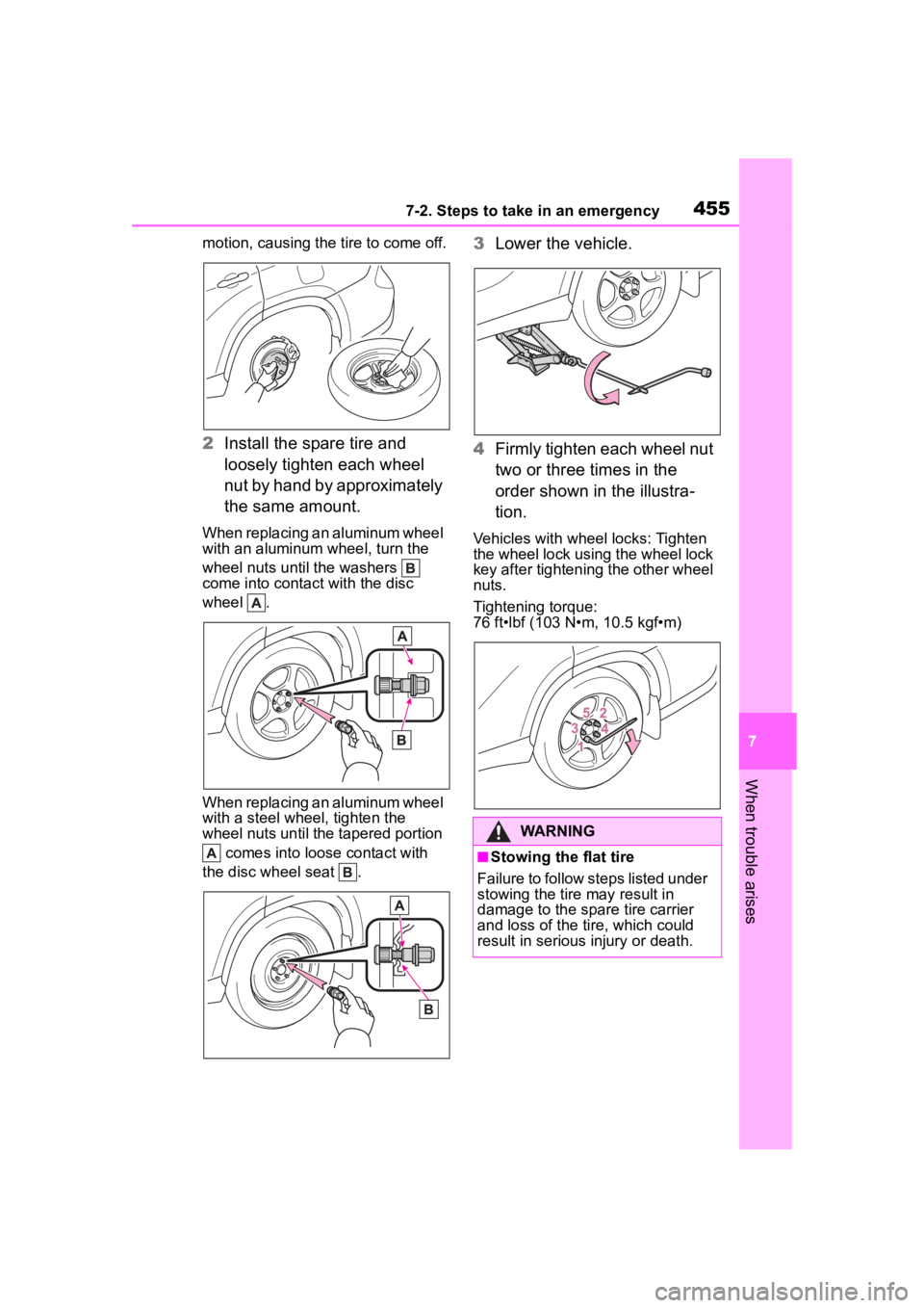
motion, causing the tire to come off.
2Install the spare tire and
loosely tighten each wheel
nut by hand by approximately
the same amount.
When replacing an aluminum wheel
with an aluminum wheel, turn the
wheel nuts until the washers
come into contact with the disc
wheel .
When replacing an aluminum wheel
with a steel wheel, tighten the
wheel nuts until the tapered portion
comes into loose contact with
the disc wheel seat .
3 Lower the vehicle.
4 Firmly tighten each wheel nut
two or three times in the
order shown in the illustra-
tion.
Vehicles with wheel locks: Tighten
the wheel lock using the wheel lock
key after tightening the other wheel
nuts.
Tightening torque:
76 ft•lbf (103 N•m, 10.5 kgf•m)
WARNING
■Stowing the flat tire
Failure to follow steps listed under
stowing the tire may result in
damage to the spare tire carrier
and loss of the tire, which could
result in serious injury or death.
Page 457 of 552
4577-2. Steps to take in an emergency
7
When trouble arises
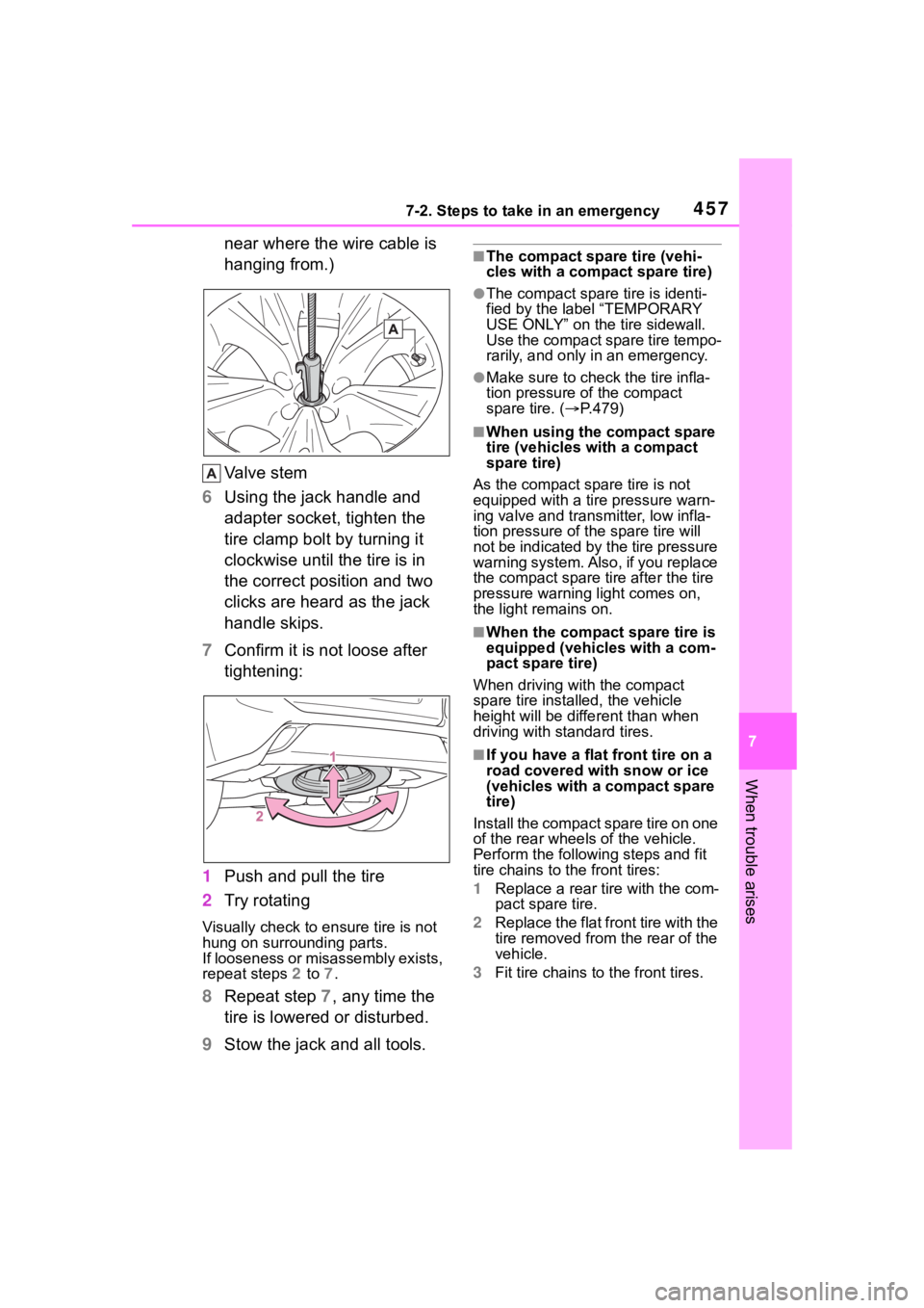
near where the wire cable is
hanging from.)
Valve stem
6 Using the jack handle and
adapter socket, tighten the
tire clamp bolt by turning it
clockwise until the tire is in
the correct position and two
clicks are heard as the jack
handle skips.
7 Confirm it is not loose after
tightening:
1 Push and pull the tire
2 Try rotating
Visually check to ensure tire is not
hung on surrounding parts.
If looseness or misassembly exists,
repeat steps 2 to 7.
8 Repeat step 7, any time the
tire is lowered or disturbed.
9 Stow the jack and all tools.
■The compact spare tire (vehi-
cles with a compact spare tire)
●The compact spare tire is identi-
fied by the label “TEMPORARY
USE ONLY” on the tire sidewall.
Use the compact spare tire tempo-
rarily, and only in an emergency.
●Make sure to check the tire infla-
tion pressure of the compact
spare tire. ( P.479)
■When using the compact spare
tire (vehicles with a compact
spare tire)
As the compact spare tire is not
equipped with a tire pressure warn-
ing valve and transm itter, low infla-
tion pressure of t he spare tire will
not be indicated by the tire pressure
warning system. Also , if you replace
the compact spare ti re after the tire
pressure warning light comes on,
the light remains on.
■When the compact spare tire is
equipped (vehicles with a com-
pact spare tire)
When driving with the compact
spare tire installed, the vehicle
height will be diffe rent than when
driving with standard tires.
■If you have a flat front tire on a
road covered wit h snow or ice
(vehicles with a compact spare
tire)
Install the compact spare tire on one
of the rear wheels of the vehicle.
Perform the following steps and fit
tire chains to the front tires:
1 Replace a rear tire with the com-
pact spare tire.
2 Replace the flat front tire with the
tire removed from the rear of the
vehicle.
3 Fit tire chains to the front tires.
Page 458 of 552
4587-2. Steps to take in an emergency
WARNING
■When using the compact
spare tire (vehicles with a
compact spare tire)
●Remember that the compact
spare tire provided is specifi-
cally designed for use with your
vehicle. Do not use your com-
pact spare tire on another vehi-
cle.
●Do not use more than one com-
pact spare tire simultaneously.
●Replace the compact spare tire
with a standard tire as soon as
possible.
●Avoid sudden acceleration,
abrupt steering, sudden brak-
ing and shifting operations that
cause sudden engine braking.
■When the compact spare tire
is attached (vehicles with a
compact spare tire)
The vehicle speed may not be
correctly detecte d, and the follow-
ing systems may not operate cor-
rectly:
• ABS & Brake assist
• VSC
• TRAC
• EPS
• Dynamic radar cruise control with full-speed range
• PCS (Pre-Collision System)
• LTA (Lane Tracing Assist)
• Automatic High Beam
• AFS (Adaptive Front-lighting System) (if equipped)
• Tire pressure warning system
• Intuitive parking assist (if equipped)
• PKSB (Parking Support Brake) (if equipped)
• Toyota parking assist monitor (if equipped)
• Panoramic view monitor (if equipped)
• BSM (Blind Spot Monitor) (if equipped)
• RCTA (if equipped)
• Navigation system (if equipped)
Also, not only c an the following
system not be utilized fully, but it
may even negatively affect the
drive-train components:
• AWD system (AWD models)
■Speed limit when using the
compact spare tire (vehicles
with a compact spare tire)
Do not drive at speeds in excess
of 50 mph (80 km /h) when a com-
pact spare tire is installed on the
vehicle.
The compact spare tire is not
designed for driving at high
speeds. Failure to observe this
precaution may lead to an acci-
dent causing death or serious
injury.
■After using the tools and jack
Before driving, ma ke sure all the
tools and jack are securely in
place in their storage location to
reduce the possibility of personal
injury during a collision or sudden
braking.
Page 459 of 552
4597-2. Steps to take in an emergency
7
When trouble arises
NOTICE
■Be careful when driving over
bumps with the compact
spare tire installed on the
vehicle (vehicles with a com-
pact spare tire)
The vehicle becomes lower when
driving with the compact spare tire
compared to when driving with
standard tires. Be careful when
driving over uneven road sur-
faces.
■Driving with tire chains and
the compact spare tire (vehi-
cles with a compact spare
tire)
Do not fit tire chains to the com-
pact spare tire. Tire chains may
damage the vehicle body and
adversely affect driving perfor-
mance.
■When replacing the tires
When removing or fitting the
wheels, tires or the tire pressure
warning valve and transmitter,
contact your Toyota dealer as the
tire pressure warning valve and
transmitter may be damaged if not
handled correctly.
■When stowing the flat tire
●Ensure that there is no object
caught between the tire and the
vehicle underbody.
●Securely tighten the spare tire
clamp bolt to hold the spare
wheel carrier by the hook.
●Stow the flat tire in the spare tire
location. Failure to do so may
cause damage to the spare tire
carrier. Proper storage reduces
the possibility of injury in a colli-
sion or during sudden braking.
●Have the flat tire repaired and
the spare tire replaced with it as
soon as possible.
■Proper storage of the spare
tire
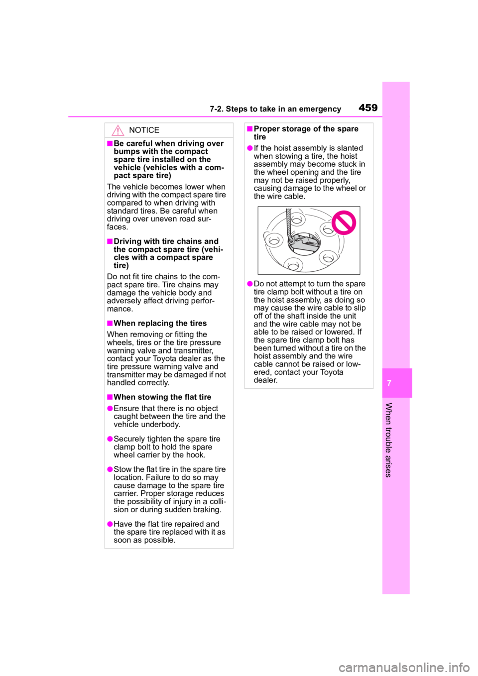
●If the hoist assembly is slanted
when stowing a tire, the hoist
assembly may become stuck in
the wheel opening and the tire
may not be raised properly,
causing damage to the wheel or
the wire cable.
●Do not attempt to turn the spare
tire clamp bolt without a tire on
the hoist assembly, as doing so
may cause the wire cable to slip
off of the shaft inside the unit
and the wire cable may not be
able to be raised or lowered. If
the spare tire clamp bolt has
been turned without a tire on the
hoist assembly and the wire
cable cannot be raised or low-
ered, contact your Toyota
dealer.
Page 464 of 552
4647-2. Steps to take in an emergency
1Ensure that the shift lever is
in P and depress the brake
pedal.
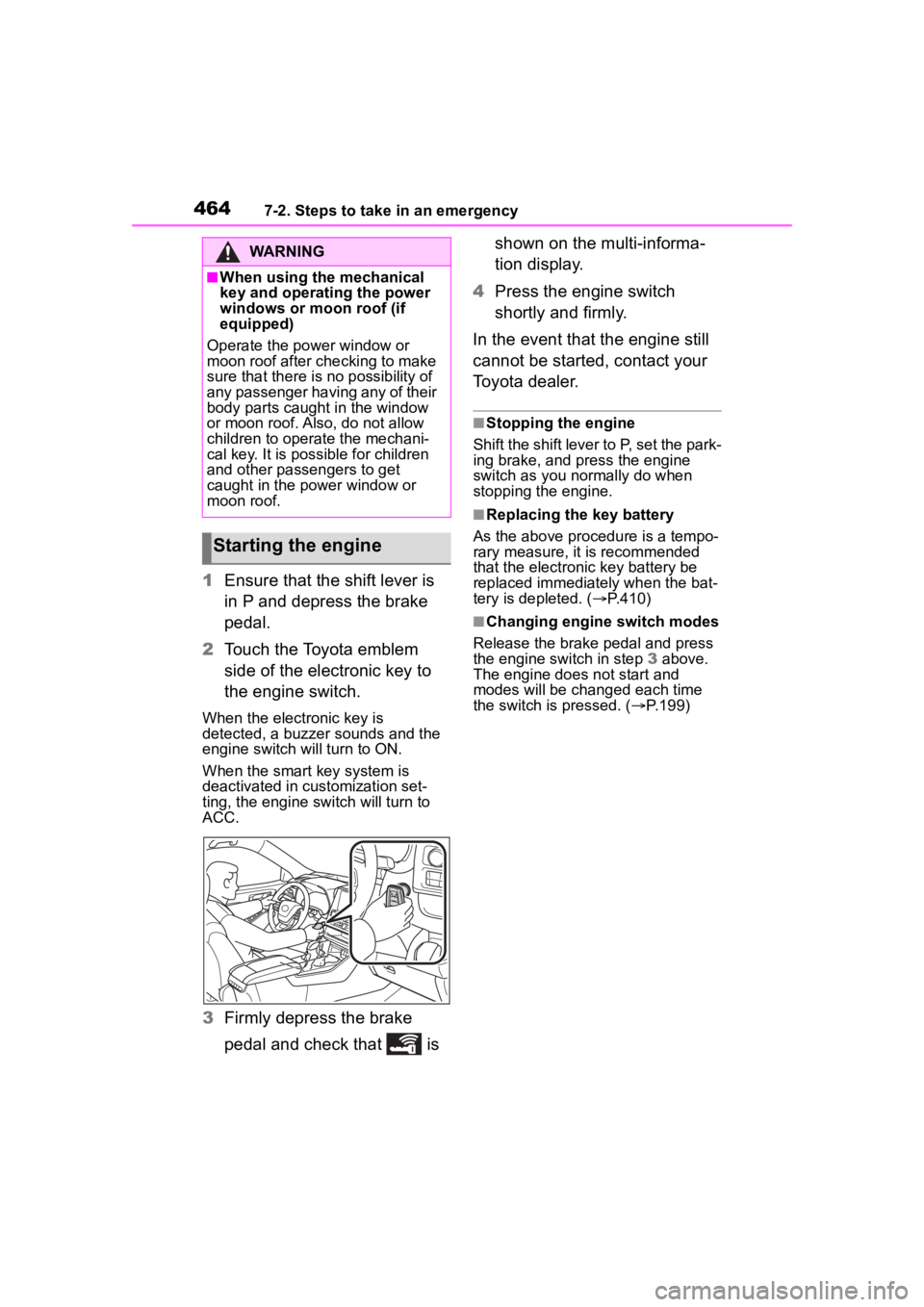
2 Touch the Toyota emblem
side of the electronic key to
the engine switch.
When the electronic key is
detected, a buzzer sounds and the
engine switch will turn to ON.
When the smart key system is
deactivated in customization set-
ting, the engine switch will turn to
ACC.
3Firmly depress the brake
pedal and check that is shown on the multi-informa-
tion display.
4 Press the engine switch
shortly and firmly.
In the event that the engine still
cannot be started, contact your
Toyota dealer.
■Stopping the engine
Shift the shift lever to P, set the park-
ing brake, and press the engine
switch as you normally do when
stopping the engine.
■Replacing the key battery
As the above proce dure is a tempo-
rary measure, it is recommended
that the electronic key battery be
replaced immediately when the bat-
tery is depleted. ( P.410)
■Changing engine switch modes
Release the brake pedal and press
the engine switch in step 3 above.
The engine does not start and
modes will be changed each time
the switch is pressed. ( P.199)
WARNING
■When using the mechanical
key and operating the power
windows or moon roof (if
equipped)
Operate the power window or
moon roof after checking to make
sure that there is n o possibility of
any passenger having any of their
body parts caught in the window
or moon roof. Al so, do not allow
children to operate the mechani-
cal key. It is possible for children
and other passengers to get
caught in the power window or
moon roof.
Starting the engine