oil temperature TOYOTA HIGHLANDER 2023 Owners Manual
[x] Cancel search | Manufacturer: TOYOTA, Model Year: 2023, Model line: HIGHLANDER, Model: TOYOTA HIGHLANDER 2023Pages: 552, PDF Size: 13.36 MB
Page 75 of 552

752-1. Instrument cluster
2
Vehicle status information and indicators
12.3-inch display
The units used on the meters and some indicators may differ
depending on the target region.
Warning lights inform the driver
of malfunctions in the indicated
vehicle’s systems.
Warning lights
(U.S.A.)
Brake system warning
light
*1 ( P.431)
(red)
(Canada)
Brake system warning
light
*1 ( P.431)
(yellow)
Brake system warning
light
*1 ( P.431)
High coolant temperature
warning light
*2 ( P.431)
Charging system warning
light
*3 ( P.432)
Low engine oil pressure
warning light
*2 ( P.432)
(U.S.A.)
Malfunction indicator
lamp
*1 ( P.432)
(Canada)
Malfunction indicator
lamp
*1 ( P.432)
SRS warning light
*1
( P.432)
(U.S.A.)
ABS warning light*1
( P.433)
(Canada)
ABS warning light*1
( P.433)
Inappropriate pedal opera-
tion warning light
*2
( P.433)
(red/yel-
low)
Electric power steering
system warning light
( P.433)
Low fuel leve l warning
light
*1( P.434)
Driver’s and front passen-
ger’s seat belt reminder
light ( P.434)
Page 80 of 552
802-1. Instrument cluster
■The meters and display illumi-
nate when
The engine switch is in ON.
■Outside temperature display
●In the following si tuations, the cor-
rect outside tempe rature may not
be displayed, or the display may
take longer than normal to
change:
• When stopped, or driving at low
speeds (less than 12 mph [20
km/h])
• When the outside temperature
has changed suddenly (at the
entrance/exit of a garage, tunnel,
etc.)
●When “--” or “E” is displayed, the
system may be malfunctioning.
Take your vehicle to your Toyota
dealer.
■Liquid crystal display
Small spots or light spots may
appear on the display. This phenom-
enon is characteristi c of liquid crys-
tal displays, and there is no problem
continuing to use the display.
■Customization
The meters can be customized on of the multi-information display.
( P.94)
■Display items
Odometer
Displays the total distance the vehi-
cle has been driven.
Trip meter A/trip meter B
Displays the distance the vehicle
has been driven since the meter
was last reset. Trip meters A and B
can be used to record and display
different distances independently.
Distance until next engine oil
change
Displays the distance the vehicle
can be driven until an oil change is
WARNING
■The information display at
low temperatures
Allow the interior of the vehicle to
warm up before u sing the liquid
crystal informat ion display. At
extremely low temperatures, the
information display monitor may
respond slowly, and display
changes may be delayed.
For example, there is a lag
between the driver’s shifting and
the new gear number appearing
on the display. This lag could
cause the driver to downshift
again, causing rapid and exces-
sive engine braking and possibly
an accident resulting in death or
injury.
NOTICE
■To prevent damage to the
engine and its components
●Do not let the indicator needle
of the tachometer enter the red
zone, which indicates the maxi-
mum engine speed.
●The engine may be overheating
if the engine coolant tempera-
ture gauge is in the red zone
(H). In this case, immediately
stop the vehicle in a safe place,
and check the engine after it
has cooled completely.
( P.469)
Odometer and trip meter
display
Page 350 of 552
3505-4. Using the other interior features
A portable device, such as a
smartphone or mobile battery,
can be charged by just placing it
on the charging area, provided
the device is compatible with the
Qi wireless charging standard
created by the Wireless Power
Consortium.
The wireless charger cannot be
used with a portable device that
is larger than the charging area.
Additionally, depending on the
portable device, the wireless
charger may not operate prop-
erly. Refer to the operation man-
ual of the portable device.
■The “Qi” logo
The “Qi” logo is a trademark of
the Wireless Power Consortium.
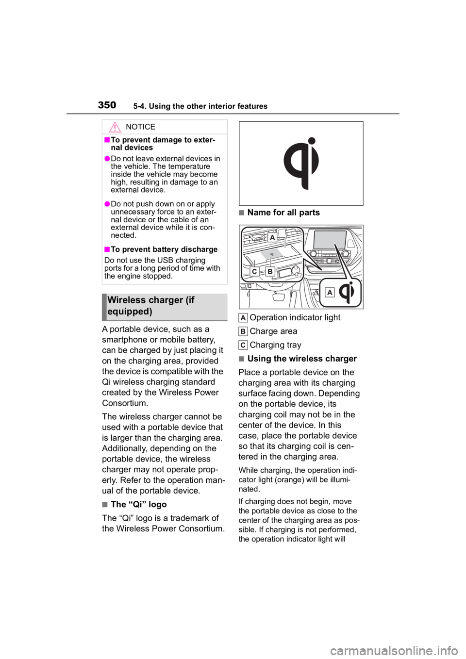
■Name for all parts
Operation indicator light
Charge area
Charging tray
■Using the wireless charger
Place a portable device on the
charging area with its charging
surface facing down. Depending
on the portable device, its
charging coil may not be in the
center of the device. In this
case, place the portable device
so that its charging coil is cen-
tered in the charging area.
While charging, the operation indi-
cator light (oran ge) will be illumi-
nated.
If charging does not begin, move
the portable device as close to the
center of the charging area as pos-
sible. If charging is not performed,
the operation indicator light will
NOTICE
■To prevent damage to exter-
nal devices
●Do not leave external devices in
the vehicle. The temperature
inside the vehicle may become
high, resulting in damage to an
external device.
●Do not push down on or apply
unnecessary force to an exter-
nal device or the cable of an
external device while it is con-
nected.
■To prevent battery discharge
Do not use the USB charging
ports for a long period of time with
the engine stopped.
Wireless charger (if
equipped)
Page 353 of 552
3535-4. Using the other interior features
5
Interior features
■The wireless charger can be
operated when
The engine switch is in ACC or ON.
■Portable devices that can be
charged
●Portable devices compatible with
the Qi wireless charging standard
can be charged by the wireless
charger. However, compatibility
with all devices which meet the Qi
wireless charging standard is not
guaranteed.
●The wireless charger is designed
to supply low power electricity (5
W or less) to a cellular phone,
smartphone, or other portable
device.
●Failure to do so may result in the
possibility of fire, However, porta- ble devices, such as the following,
can be charged with more than 5
W.
• 7.5 W charging compatible iPhones can be charged at 7.5 W
or less.
• Portable devices which conform to WPC Ver 1.2.4 (Extended Power
profile ) can be charged at 10 W or
less.
■If a cover or accessory is
attached to the portable device
Do not charge a portable device if a
cover or accessory w hich is not Qi
compatible is atta ched. Depending
on the type of cover (including for
certain genuine manufacturer parts)
and/or accessory a ttached, it may
not be possible to charge the porta-
ble device. If the portable device is
placed on the charging area and
Orange
(Repeatedly
flashes 3 times
continuously)
Gray
Foreign substance detection:
A metallic foreign substance is in the
charge area, and so the abnormal heat-
ing prevention function of the charging
coil operated
→Remove the foreign substance from
the charge area.
Portable device misaligned:
→The charging coil in the portable
device moved outside of the charge
area, and so the abnormal heating pre-
vention function of the charging coil
operated
Orange
(Repeatedly
flashes 4 times
continuously)
Gray
Safety shutdown resulting when the
temperature within the wireless charger
exceeded the set value
→Stop charging, remove the portable
device from the charging tray, wait for
the temperature to drop, and then start
charging again.
Operation indicator lightSuspected causes/Handling methodCharging trayCenter display
Page 355 of 552
3555-4. Using the other interior features
5
Interior features
WARNING
●Do not use the charging tray as
a small storage space.
●Do not subject to a strong force
or impact.
●Do not disassemble, modify or
remove the wireless charger.
●Do not charge devices other
than specified portable devices.
●Keep away from magnetic
items.
●Do not charge devices if the
charge area is covered in dust.
●Do not cover with a cloth or sim-
ilar material.
NOTICE
■Situations in which the func-
tion may not operate normally
Devices may not be charged nor-
mally in the following situations.
●The portable device is fully
charged
●The portable device is being
charged with a cable connected
●There is foreign matter between
the charge area and portable
device
●Charging has caused the porta-
ble device to heat up
●The temperature around the
charging tray is 95°F (35°C) or
higher, such as in extreme heat
●The portable device is placed
with its charging side facing up
●The portable device is placed in
an area misaligned from the
charge area
●The portable device is larger
than the charging tray
●A foldable and portable device
is placed outside the charge
area
●The camera lens protrudes 0.12
in. (3 mm) or more from the sur-
face of the portal device
●The vehicle is in an area where
strong electrical waves or noise
are emitted, such as near a tele-
vision tower, power plant, gaso-
line station, broadcasting
station, large display, airport,
etc.
●Any of the following objects that
is protrudes 0.08 in. (2 mm) or
thicker is stuck or installed
between the charging side of
the portable device and the
charge area.
• Thick cases or covers
• A case or cover attached with an uneven or tilt ed surface, so
that the charging side is not flat
• Thick decorations
• Accessories, such as finger- rings, straps, etc.
●When the portable device is in
contact with, or is covered by
any of the following metallic
objects:
• A card that has metal on it, such as aluminum foil, etc.
• A pack of cigarettes that includes aluminum foil
• A wallet or bag that is made of metal
• Coins
• A heating pad
• CDs, DVDs or other media
Page 383 of 552
3836-3. Do-it-yourself maintenance
6
Maintenance and care
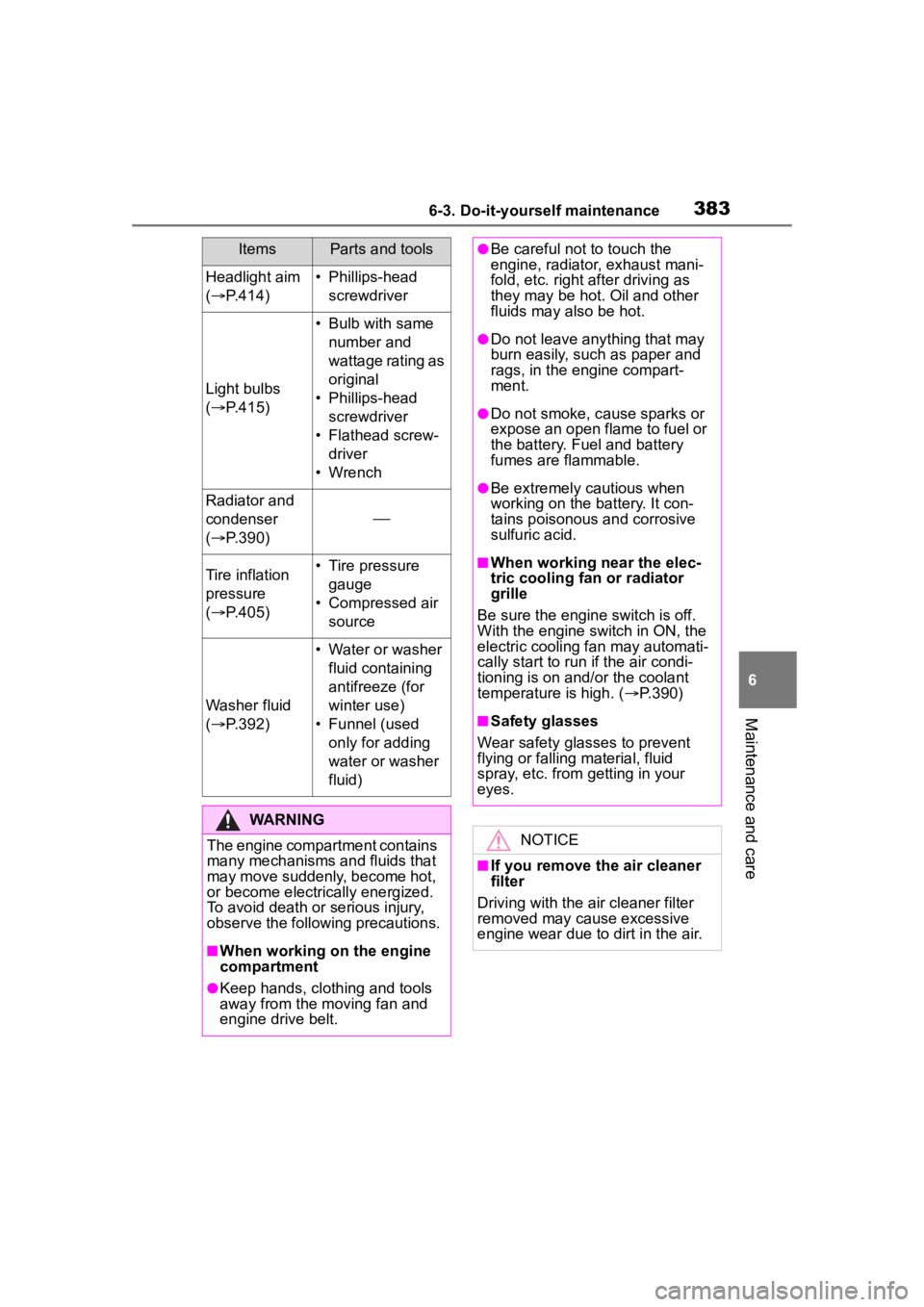
Headlight aim
( P.414)• Phillips-head
screwdriver
Light bulbs
( P.415)
• Bulb with same
number and
wattage rating as
original
• Phillips-head screwdriver
• Flathead screw- driver
• Wrench
Radiator and
condenser
( P.390)
Tire inflation
pressure
( P.405)• Tire pressure
gauge
• Compressed air source
Washer fluid
( P.392)
• Water or washer
fluid containing
antifreeze (for
winter use)
• Funnel (used only for adding
water or washer
fluid)
WARNING
The engine compartment contains
many mechanisms and fluids that
may move suddenly, become hot,
or become electrically energized.
To avoid death or serious injury,
observe the following precautions.
■When working on the engine
compartment
●Keep hands, clothing and tools
away from the moving fan and
engine drive belt.
ItemsParts and tools●Be careful not to touch the
engine, radiator, exhaust mani-
fold, etc. right a fter driving as
they may be hot. Oil and other
fluids may also be hot.
●Do not leave anything that may
burn easily, such as paper and
rags, in the engine compart-
ment.
●Do not smoke, cause sparks or
expose an open flame to fuel or
the battery. Fuel and battery
fumes are flammable.
●Be extremely cautious when
working on the battery. It con-
tains poisonous and corrosive
sulfuric acid.
■When working near the elec-
tric cooling fan or radiator
grille
Be sure the engine switch is off.
With the engine switch in ON, the
electric cooling fa n may automati-
cally start to run if the air condi-
tioning is on and/or the coolant
temperature is high. ( P.390)
■Safety glasses
Wear safety glasses to prevent
flying or falling material, fluid
spray, etc. from getting in your
eyes.
NOTICE
■If you remove the air cleaner
filter
Driving with the air cleaner filter
removed may cause excessive
engine wear due to dirt in the air.
Page 386 of 552
3866-3. Do-it-yourself maintenance
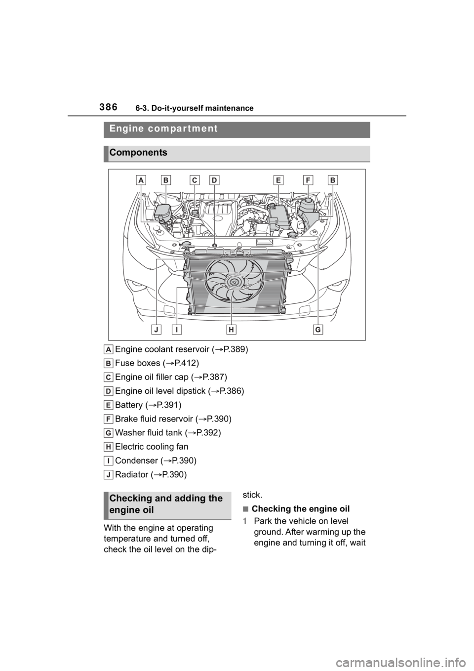
Engine coolant reservoir ( P.389)
Fuse boxes ( P.412)
Engine oil filler cap ( P.387)
Engine oil level dipstick ( P.386)
Battery ( P.391)
Brake fluid reservoir ( P.390)
Washer fluid tank ( P.392)
Electric cooling fan
Condenser ( P.390)
Radiator ( P.390)
With the engine at operating
temperature and turned off,
check the oil level on the dip- stick.
■Checking the engine oil
1 Park the vehicle on level
ground. After warming up the
engine and turning it off, wait
Engine compar tment
Components
Checking and adding the
engine oil
Page 476 of 552
4768-1. Specifications
■Oil capacity (Drain and
refillreference
*)
*: The engine oil capacity is a refer-
ence quantity to be used when
changing the engine oil. Warm up
and turn off the engine, wait more
than 5 minutes, and check the oil
level on the dipstick.
■Engine oil selection
“Toyota Genuine Motor Oil” is
used in your Toyota vehicle. Use
Toyota approved “Toyota Genu-
ine Motor Oil” or equivalent to
satisfy the following grade and
viscosity.
Oil grade: ILSAC GF-6A multi-
grade engine oil
Recommended viscosity: SAE
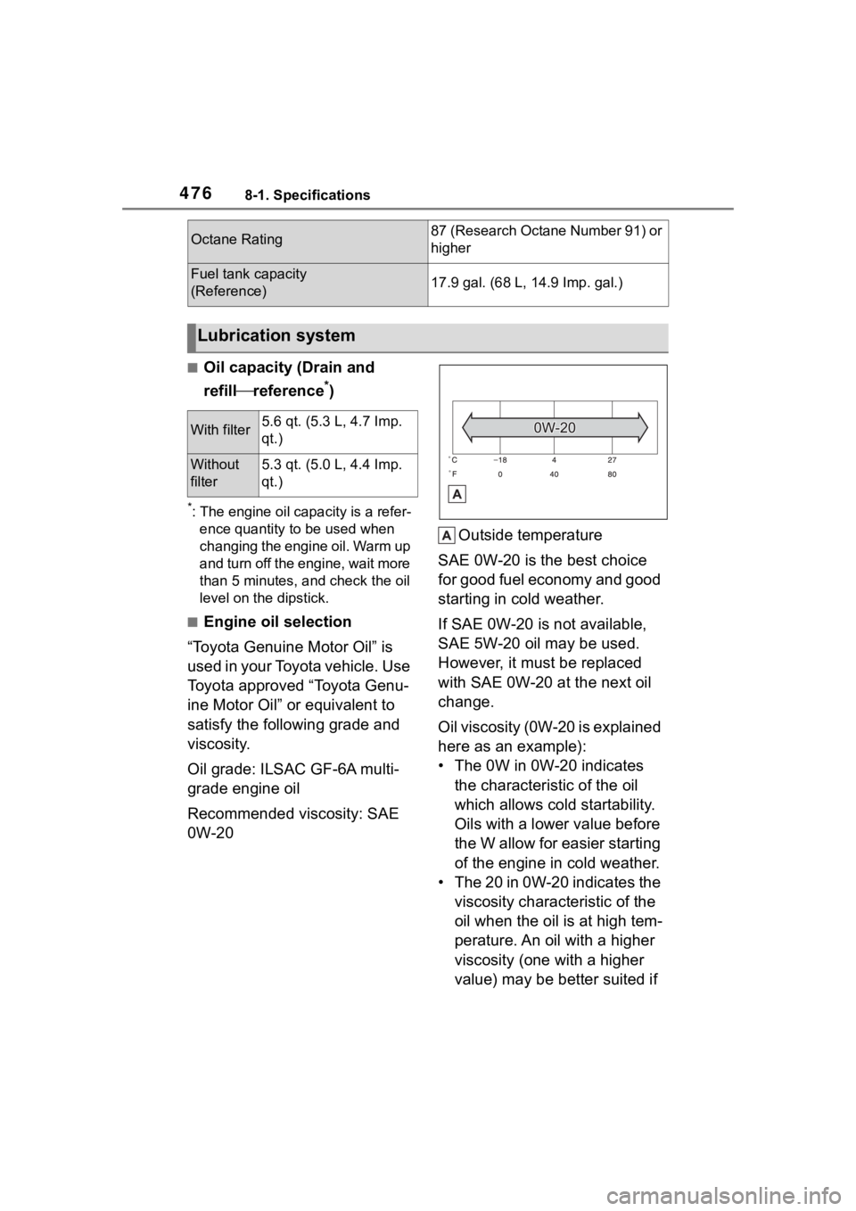
0W-20 Outside temperature
SAE 0W-20 is the best choice
for good fuel economy and good
starting in cold weather.
If SAE 0W-20 is not available,
SAE 5W-20 oil may be used.
However, it must be replaced
with SAE 0W-20 at the next oil
change.
Oil viscosity (0W-20 is explained
here as an example):
• The 0W in 0W-20 indicates the characteristic of the oil
which allows cold startability.
Oils with a lower value before
the W allow for easier starting
of the engine in cold weather.
• The 20 in 0W-20 indicates the viscosity characteristic of the
oil when the oil is at high tem-
perature. An oil with a higher
viscosity (one with a higher
value) may be better suited if
Octane Rating87 (Research Octane Number 91) or
higher
Fuel tank capacity
(Reference)17.9 gal. (68 L, 14.9 Imp. gal.)
Lubrication system
With filter5.6 qt. (5.3 L, 4.7 Imp.
qt.)
Without
filter5.3 qt. (5.0 L, 4.4 Imp.
qt.)
Page 488 of 552
4888-1. Specifications
Grade C corresponds to a level of
performance which all passenger
car tires must meet under the Fed-
eral Motor Vehicle Safety Standard
No. 109.
Grades B and A represent higher
levels of performance on the labo-
ratory test wheel than the minimum
required by law. Warning: The temperature grades
of a tire assume tha
t it is properly
inflated and not overloaded.
Excessive speed, underinflation, or
excessive loading, either sepa-
rately or in combination, can cause
heat buildup and possible tire fail-
ure.
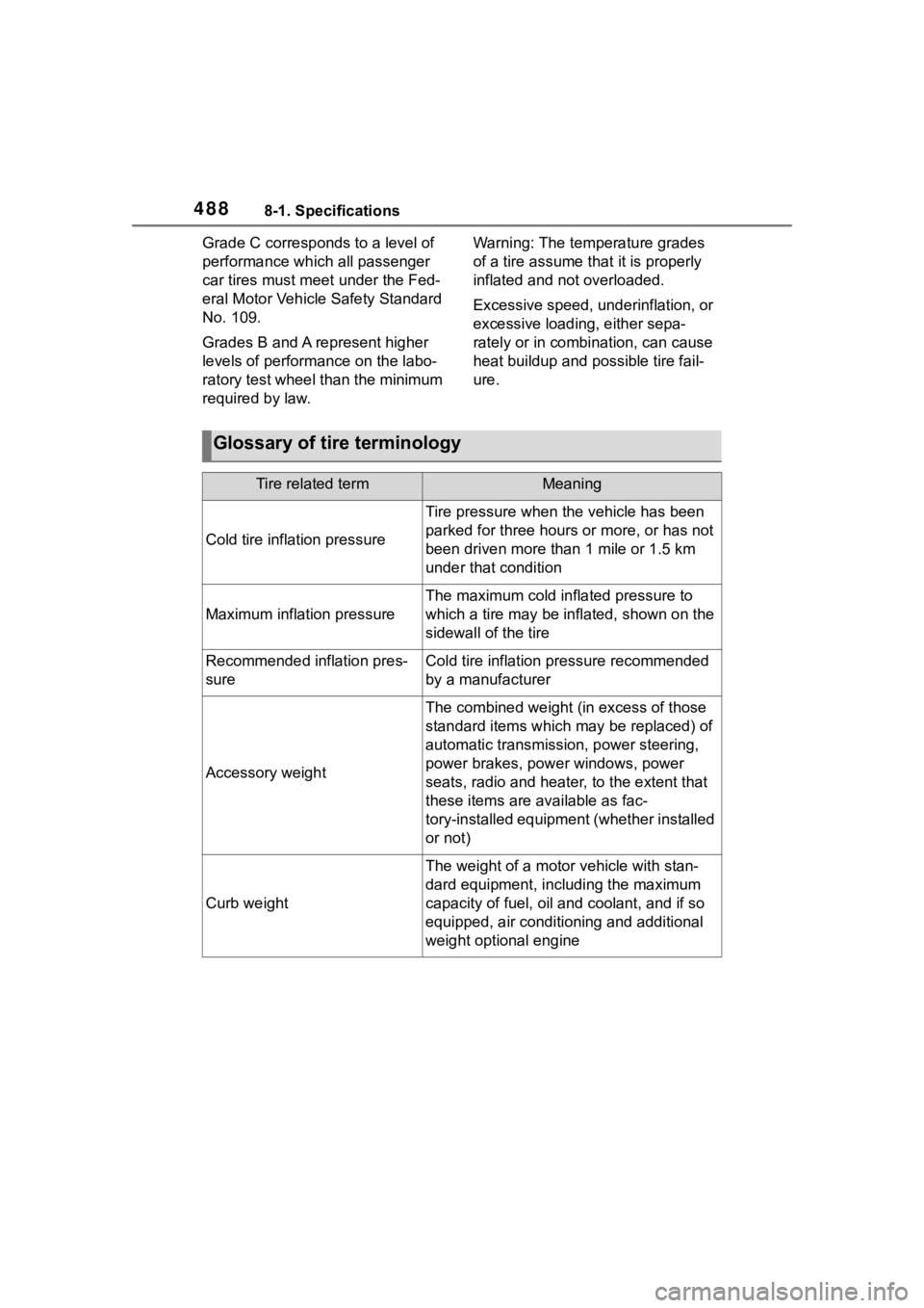
Glossary of tire terminology
Tire related termMeaning
Cold tire infl ation pressure
Tire pressure when the vehicle has been
parked for three hours or more, or has not
been driven more than 1 mile or 1.5 km
under that condition
Maximum inflation pressure
The maximum cold inf lated pressure to
which a tire may be inflated, shown on the
sidewall of the tire
Recommended inflation pres-
sureCold tire inflation pressure recommended
by a manufacturer
Accessory weight
The combined weight (in excess of those
standard items which may be replaced) of
automatic transmission, power steering,
power brakes, power windows, power
seats, radio and heater, to the extent that
these items are available as fac-
tory-installed equipment (whether installed
or not)
Curb weight
The weight of a motor vehicle with stan-
dard equipment, including the maximum
capacity of fuel, oil and coolant, and if so
equipped, air conditioning and additional
weight optional engine
Page 528 of 552
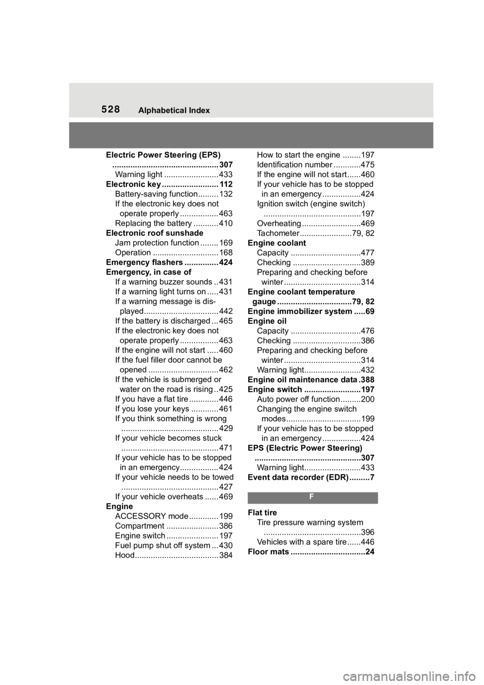
528Alphabetical Index
Electric Power Steering (EPS)............................................... 307Warning light ........................ 433
Electronic key ......................... 112 Battery-saving function......... 132
If the electronic key does not operate properly ................. 463
Replacing the battery ........... 410
Electronic roof sunshade Jam protection function ........ 169
Operation ............................. 168
Emergency flashers ............... 424
Emergency, in case of If a warning buzzer sounds .. 431
If a warning light turns on ..... 431
If a warning message is dis-played................................. 442
If the battery is discharged ... 465
If the electronic key does not operate properly ................. 463
If the engin e will not start ..... 460
If the fuel filler door cannot be opened ............................... 462
If the vehicle is submerged or water on the road is rising .. 425
If you have a flat tire ............. 446
If you lose your keys ............ 461
If you think something is wrong ........................................... 429
If your vehicle becomes stuck ........................................... 471
If your vehicle has to be stopped in an emergency................. 424
If your vehicle needs to be towed ........................................... 427
If your vehicle overheats ...... 469
Engine ACCESSORY mode ............. 199
Compartment ....................... 386
Engine switch ....................... 197
Fuel pump shut off system ... 430
Hood..................................... 384 How to start the engine ........197
Identification number ............475
If the engine will not start......460
If your vehicle has to be stopped
in an emergency .................424
Ignition switch (engine switch) ...........................................197
Overheating ..........................469
Tachometer.......................79, 82
Engine coolant Capacity ...............................477
Checking ..............................389
Preparing and checking before winter ..................................314
Engine coolant temperature gauge .................................79, 82
Engine immobilizer system .....69
Engine oil Capacity ...............................476
Checking ..............................386
Preparing and checking before winter ..................................314
Warning light.........................432
Engine oil maintenance data .388
Engine switch .........................197 Auto power off fun ction .........200
Changing the engine switch modes.................................199
If your vehicle has to be stopped in an emergency .................424
EPS (Electric Po wer Steering)
...............................................307 Warning light.........................433
Event data recorder (EDR) .........7
F
Flat tire Tire pressure w arning system
...........................................396
Vehicles with a spare tire......446
Floor mats .................................24