clock TOYOTA HIGHLANDER HYBRID 2021 Owners Manual (in English)
[x] Cancel search | Manufacturer: TOYOTA, Model Year: 2021, Model line: HIGHLANDER HYBRID, Model: TOYOTA HIGHLANDER HYBRID 2021Pages: 578, PDF Size: 16.92 MB
Page 90 of 578
902-1. Instrument cluster
HIGHLANDER HV_U
Clock (P. 9 2 )
Speedometer
Fuel gauge
Displays the quantity of fuel remaining in the tank
Odometer and trip meter display ( P.91)
Shift position display ( P.220)
Outside temperature
Displays the outside temperature within the range of -40°F (-40°C) to 122°F
(50°C). Low outside temperature indicator comes on when the ambient
temperature is 37°F (3°C) or lower.
Engine coolant temperature gauge
Displays the engine coolant temperature
■The meters and display illumi-
nate when
The power switch is in ON.
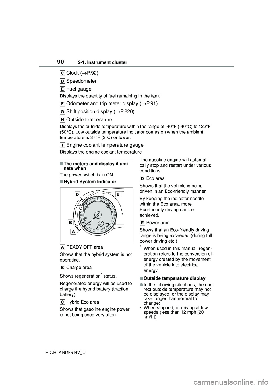
■Hybrid System Indicator
READY OFF area
Shows that the hybrid system is not
operating.
Charge area
Shows regeneration
* status.
Regenerated energy will be used to
charge the hybrid battery (traction
battery).
Hybrid Eco area
Shows that gasoline engine power
is not being used very often. The gasoline engine
will automati-
cally stop and restart under various
conditions.
Eco area
Shows that the vehicle is being
driven in an Eco-friendly manner.
By keeping the indicator needle
within the Eco area, more
Eco-friendly driving can be
achieved.
Power area
Shows that an Eco-friendly driving
range is being exceeded (during full
power driving etc.)
*: When used in this manual, regen- eration refers to the conversion of
energy created by the movement
of the vehicle into electrical
energy.
■Outside temperature display
●In the following situations, the cor-
rect outside temperature may not
be displayed, or the display may
take longer th an normal to
change:
• When stopped, or driving at low speeds (less than 12 mph [20
km/h])
Page 92 of 578
922-1. Instrument cluster
HIGHLANDER HV_U
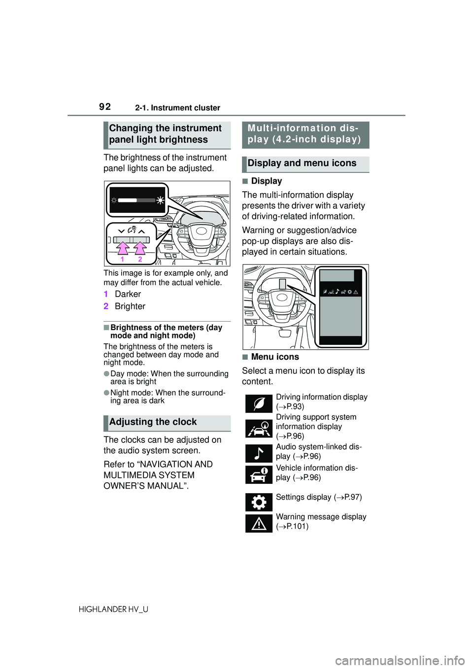
The brightness of the instrument
panel lights can be adjusted.
This image is for example only, and
may differ from the actual vehicle.
1Darker
2 Brighter
■Brightness of the meters (day
mode and night mode)
The brightness of the meters is
changed between day mode and
night mode.
●Day mode: When the surrounding
area is bright
●Night mode: When the surround-
ing area is dark
The clocks can be adjusted on
the audio system screen.
Refer to “NAVIGATION AND
MULTIMEDIA SYSTEM
OWNER’S MANUAL”.
■Display
The multi-information display
presents the driver with a variety
of driving-related information.
Warning or suggestion/advice
pop-up displays are also dis-
played in certain situations.
■Menu icons
Select a menu icon to display its
content.
Changing the instrument
panel light brightness
Adjusting the clock
Multi-infor mation dis-
play (4.2-inch display)
Display and menu icons
Driving information display
( P. 9 3 )
Driving support system
information display
( P. 9 6 )
Audio system-linked dis-
play ( P. 9 6 )
Vehicle information dis-
play ( P. 9 6 )
Settings display ( P.97)
Warning message display
( P.101)
Page 343 of 578
3435-2. Using the air conditioning system and defogger
5
Interior features
HIGHLANDER HV_U
Windshield wiper de-icer switch
■Adjusting the temperature
setting
Turn driver’s side temperature
control switch clockwise to
increases the temperature and
turn the switch counterclockwise
to decreases the temperature.
If “A/C” switch is not pressed, the
system will blow ambient tempera-
ture air or heated air.
The temperature for the driver,
front passenger and rear seats
can be adjusted separately
when:
“SYNC” control knob is
moved upward or downward.
(The “PASS” and “REAR” dis-
plays disappear)
The passenger’s side tem-
perature control switch is
turned. (The “PASS” display
disappears)
The rear seat temperature
contorl knob is moved upward
or downward. (The “REAR”
display disappears)
To the air conditioning system
switches between individual and
simultaneous modes move “SYNC”
control knob upward or downward.
■Setting the fan speed
To set the fan speed, move the
fan speed control knob upward
or downward.
Upward: Increases the fan speed
Downward: Decreases the fan speed
Pressing the “OFF” switch to turns
off the fan.
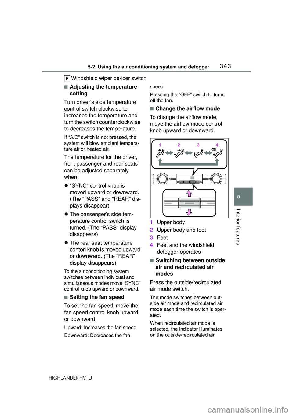
■Change the airflow mode
To change the airflow mode,
move the airflow mode control
knob upward or downward.
1 Upper body
2 Upper body and feet
3 Feet
4 Feet and the windshield
defogger operates
■Switching between outside
air and recirculated air
modes
Press the outside/recirculated
air mode switch.
The mode switches between out-
side air mode and recirculated air
mode each time the switch is oper-
ated.
When recirculated air mode is
selected, the indicator illuminates
on the outside/recirculated air
Page 417 of 578
4176-3. Do-it-yourself maintenance
6
Maintenance and care
HIGHLANDER HV_U
stick.
■Checking the engine oil
1 Park the vehicle on level
ground. After warming up the
engine and turning off the
hybrid system, wait more
than 5 minutes for the oil to
drain back into the bottom of
the engine.
2 Holding a rag under the end,
pull the dipstick out.
3 Wipe the dipstick clean.
4 Reinsert the dipstick fully.
5 Holding a rag under the end,
pull the dipstick out and
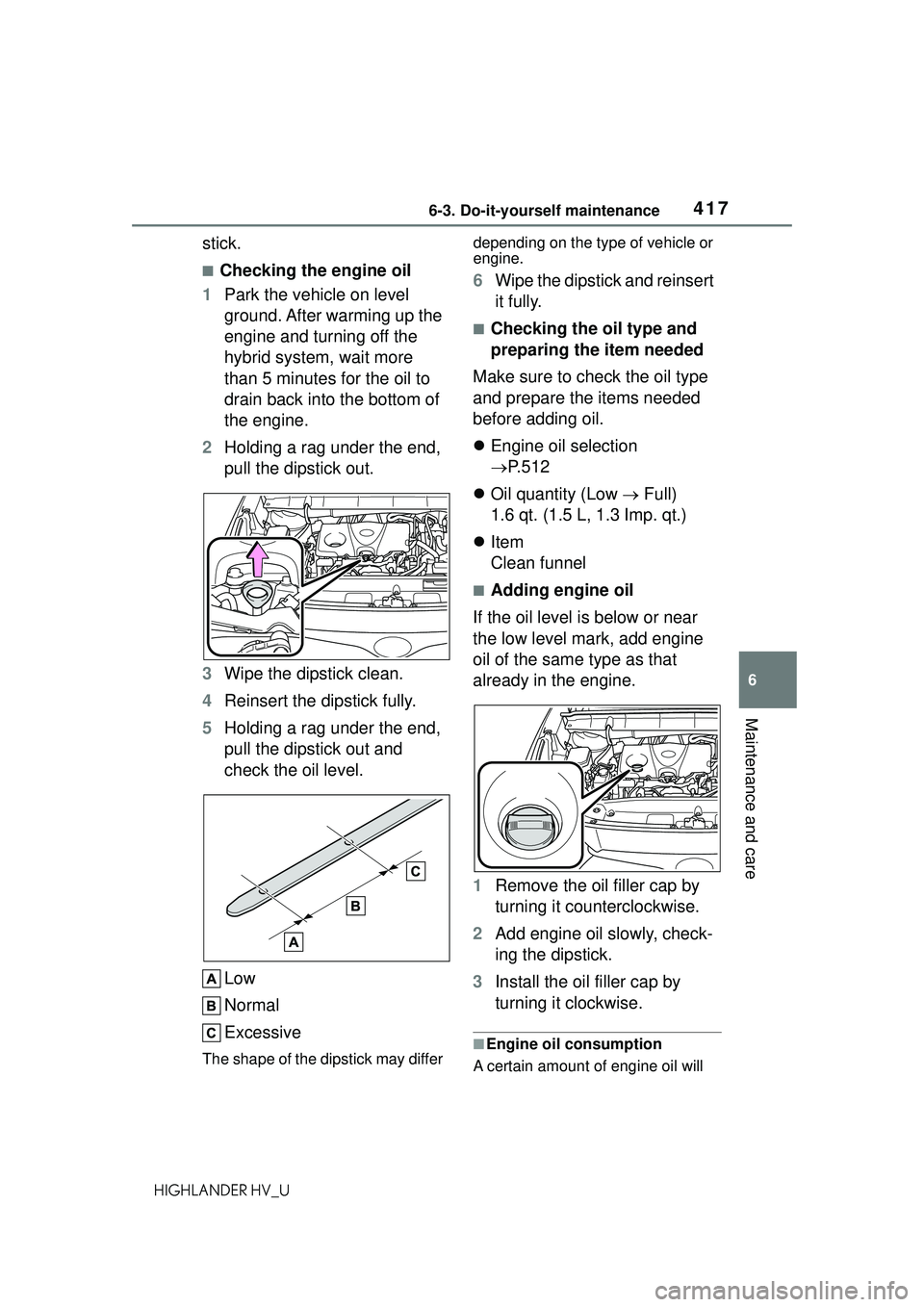
check the oil level.
Low
Normal
Excessive
The shape of the dipstick may differ depending on the type of vehicle or
engine.
6
Wipe the dipstick and reinsert
it fully.
■Checking the oil type and
preparing the item needed
Make sure to check the oil type
and prepare the items needed
before adding oil.
Engine oil selection
P.512
Oil quantity (Low Full)
1.6 qt. (1.5 L, 1.3 Imp. qt.)
Item
Clean funnel
■Adding engine oil
If the oil level is below or near
the low level mark, add engine
oil of the same type as that
already in the engine.
1 Remove the oil filler cap by
turning it counterclockwise.
2 Add engine oil slowly, check-
ing the dipstick.
3 Install the oil filler cap by
turning it clockwise.
■Engine oil consumption
A certain amount of engine oil will
Page 451 of 578
4516-3. Do-it-yourself maintenance
6
Maintenance and care
HIGHLANDER HV_Uon the inside of the lens.
●Water has built up inside the light.
■When replacing light bulbs
P. 4 4 7
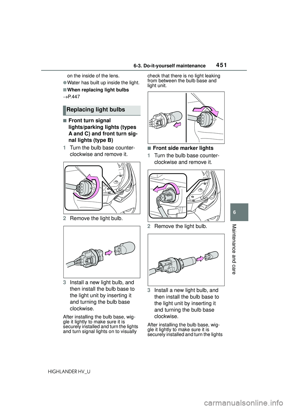
■Front turn signal
lights/parking lights (types
A and C) and front turn sig-
nal lights (type B)
1 Turn the bulb base counter-
clockwise and remove it.
2 Remove the light bulb.
3 Install a new light bulb, and
then install the bulb base to
the light unit by inserting it
and turning the bulb base
clockwise.
After installing the bulb base, wig-
gle it lightly to make sure it is
securely installed and turn the lights
and turn signal lights on to visually check that there is no light leaking
from between the bulb base and
light unit.
■Front side marker lights
1 Turn the bulb base counter-
clockwise and remove it.
2 Remove the light bulb.
3 Install a new light bulb, and
then install the bulb base to
the light unit by inserting it
and turning the bulb base
clockwise.
After installing the bulb base, wig-
gle it lightly to make sure it is
securely installed and turn the lights
Replacing light bulbs
Page 452 of 578
4526-3. Do-it-yourself maintenance
HIGHLANDER HV_Uon to visually check that there is no
light leaking from between the bulb
base and light unit.
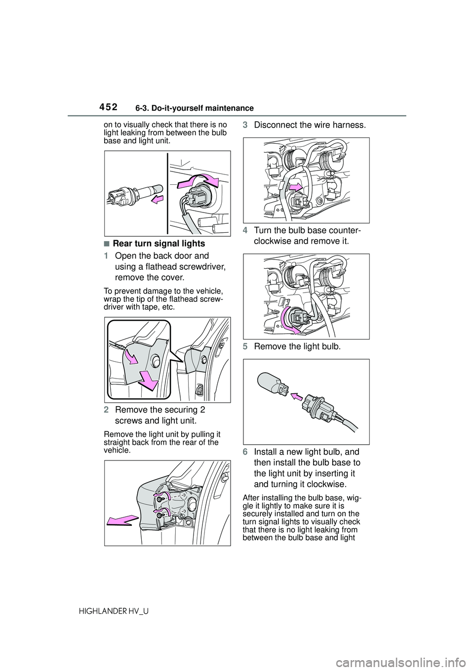
■Rear turn signal lights
1 Open the back door and
using a flathead screwdriver,
remove the cover.
To prevent damage to the vehicle,
wrap the tip of the flathead screw-
driver with tape, etc.
2Remove the securing 2
screws and light unit.
Remove the light unit by pulling it
straight back from the rear of the
vehicle.
3Disconnect the wire harness.
4 Turn the bulb base counter-
clockwise and remove it.
5 Remove the light bulb.
6 Install a new light bulb, and
then install the bulb base to
the light unit by inserting it
and turning it clockwise.
After installing the bulb base, wig-
gle it lightly to make sure it is
securely installed and turn on the
turn signal lights to visually check
that there is no light leaking from
between the bulb base and light
Page 453 of 578
4536-3. Do-it-yourself maintenance
6
Maintenance and care
HIGHLANDER HV_Uunit.
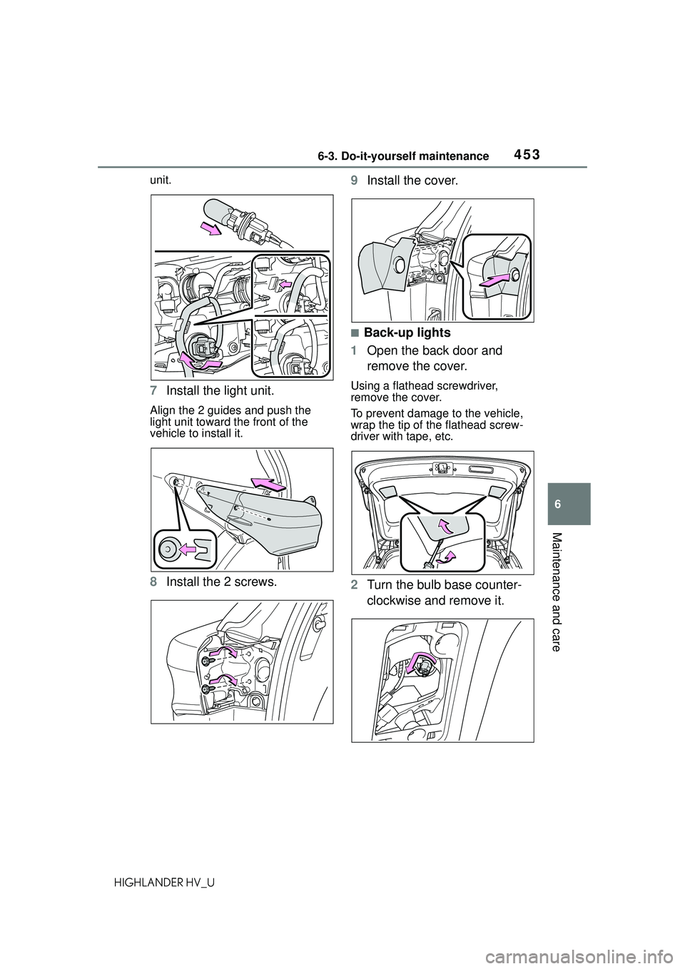
7
Install the light unit.
Align the 2 guides and push the
light unit toward the front of the
vehicle to install it.
8Install the 2 screws. 9
Install the cover.
■Back-up lights
1 Open the back door and
remove the cover.
Using a flathead screwdriver,
remove the cover.
To prevent damage to the vehicle,
wrap the tip of the flathead screw-
driver with tape, etc.
2Turn the bulb base counter-
clockwise and remove it.
Page 454 of 578
4546-3. Do-it-yourself maintenance
HIGHLANDER HV_U
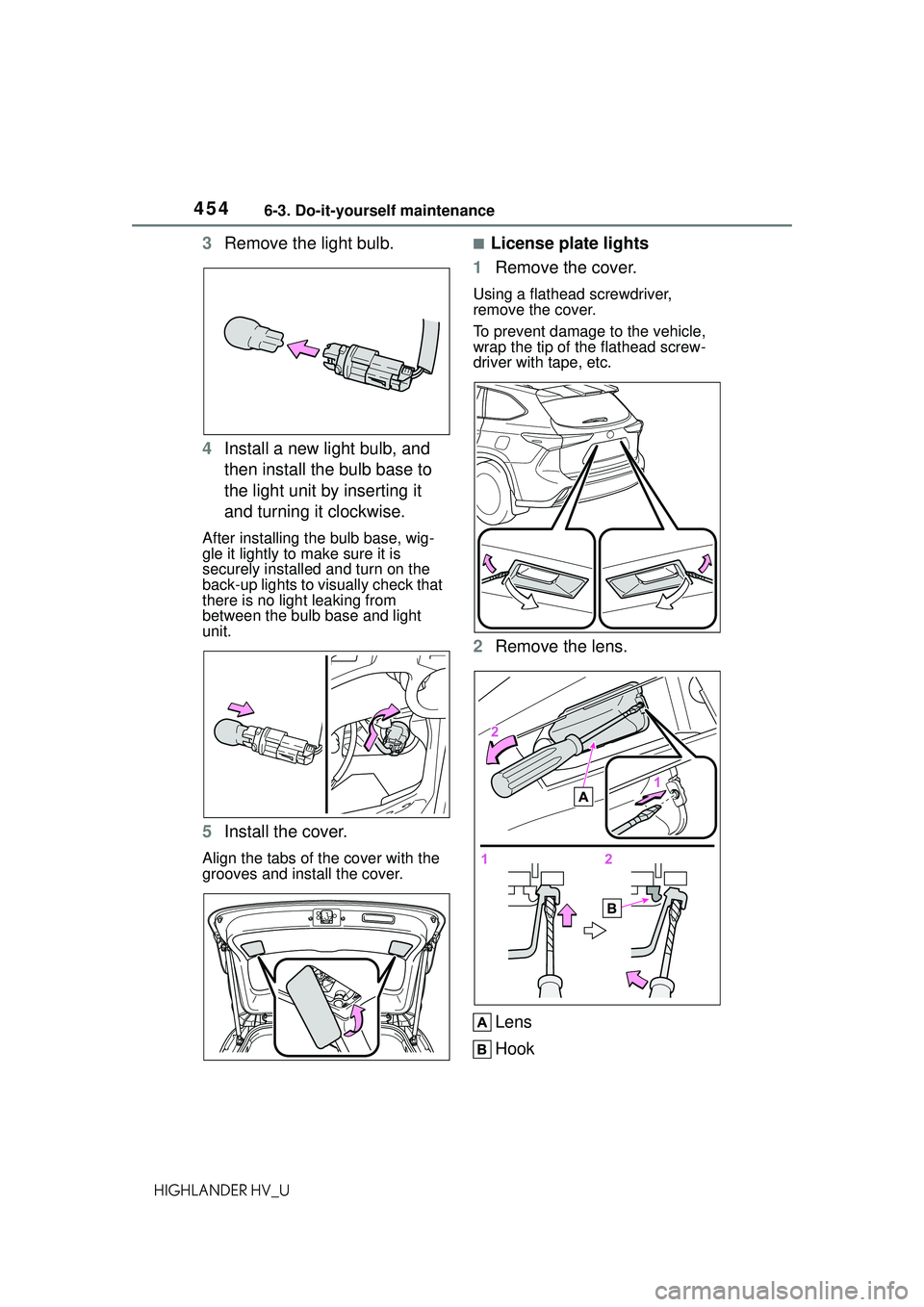
3Remove the light bulb.
4 Install a new light bulb, and
then install the bulb base to
the light unit by inserting it
and turning it clockwise.
After installing the bulb base, wig-
gle it lightly to make sure it is
securely installed and turn on the
back-up lights to visually check that
there is no light leaking from
between the bulb base and light
unit.
5Install the cover.
Align the tabs of the cover with the
grooves and install the cover.
■License plate lights
1 Remove the cover.
Using a flathead screwdriver,
remove the cover.
To prevent damage to the vehicle,
wrap the tip of the flathead screw-
driver with tape, etc.
2Remove the lens.
Lens
Hook
Page 485 of 578
4857-2. Steps to take in an emergency
7
When trouble arises
HIGHLANDER HV_U
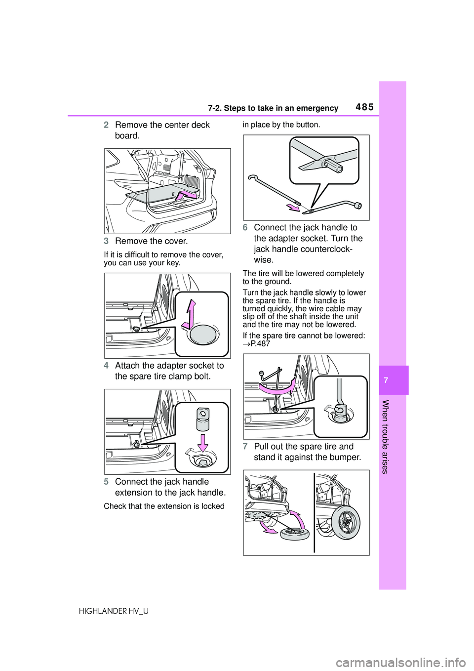
2Remove the center deck
board.
3 Remove the cover.
If it is difficult to remove the cover,
you can use your key.
4Attach the adapter socket to
the spare tire clamp bolt.
5 Connect the jack handle
extension to the jack handle.
Check that the extension is locked in place by the button.
6
Connect the jack handle to
the adapter socket. Turn the
jack handle counterclock-
wise.
The tire will be lo wered completely
to the ground.
Turn the jack handle slowly to lower
the spare tire. If the handle is
turned quickly, the wire cable may
slip off of the shaft inside the unit
and the tire may not be lowered.
If the spare tire cannot be lowered:
P.487
7 Pull out the spare tire and
stand it against the bumper.
Page 487 of 578
4877-2. Steps to take in an emergency
7
When trouble arises
HIGHLANDER HV_U
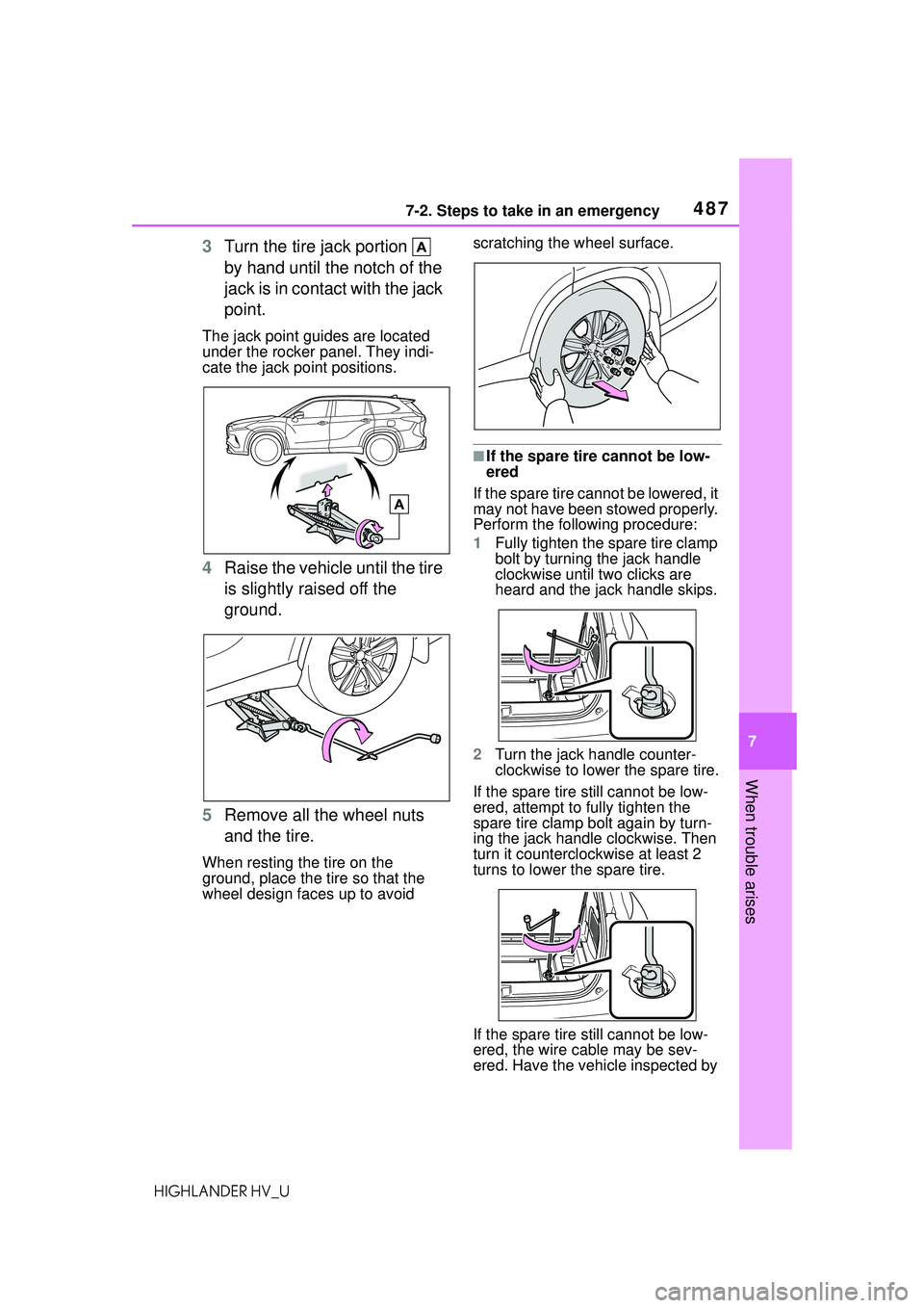
3Turn the tire jack portion
by hand until the notch of the
jack is in contact with the jack
point.
The jack point guides are located
under the rocker panel. They indi-
cate the jack point positions.
4Raise the vehicle until the tire
is slightly raised off the
ground.
5 Remove all the wheel nuts
and the tire.
When resting the tire on the
ground, place the tire so that the
wheel design faces up to avoid scratching the wheel surface.
■If the spare tire cannot be low-
ered
If the spare tire cannot be lowered, it
may not have been stowed properly.
Perform the following procedure:
1 Fully tighten the spare tire clamp
bolt by turning the jack handle
clockwise until two clicks are
heard and the jack handle skips.
2 Turn the jack handle counter-
clockwise to lower the spare tire.
If the spare tire still cannot be low-
ered, attempt to fully tighten the
spare tire clamp bolt again by turn-
ing the jack handle clockwise. Then
turn it counterclockwise at least 2
turns to lower the spare tire.
If the spare tire still cannot be low-
ered, the wire cable may be sev-
ered. Have the vehicle inspected by