instrument panel TOYOTA HIGHLANDER HYBRID 2023 Owners Manual
[x] Cancel search | Manufacturer: TOYOTA, Model Year: 2023, Model line: HIGHLANDER HYBRID, Model: TOYOTA HIGHLANDER HYBRID 2023Pages: 572, PDF Size: 14.07 MB
Page 15 of 572
15Pictorial index
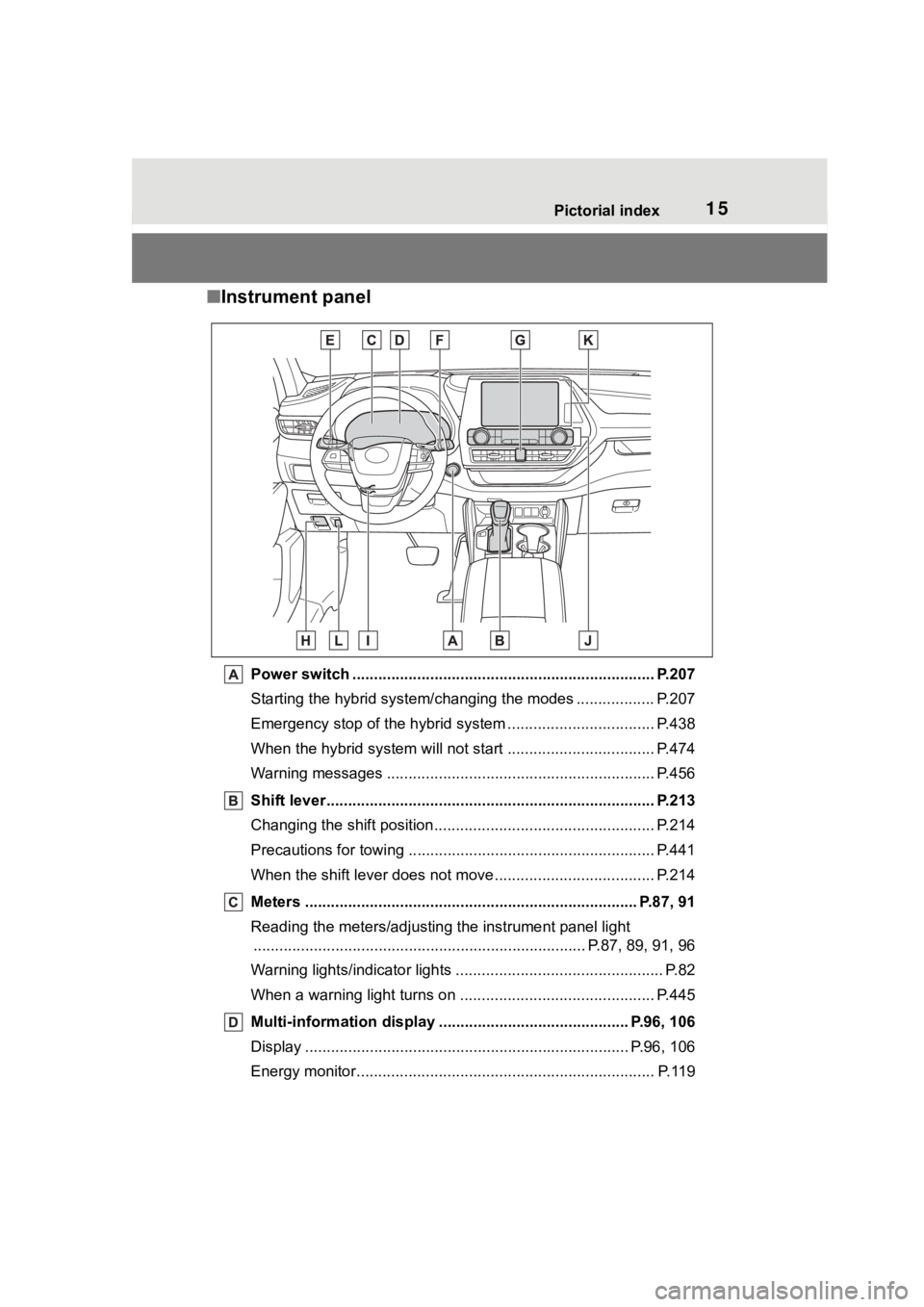
■Instrument panel
Power switch ................................................... ................... P.207
Starting the hybrid system/changing the modes .................. P. 2 0 7
Emergency stop of the hybrid system ............................ ...... P.438
When the hybrid system will not start .......................... ........ P.474
Warning messages ............................................... ............... P.456
Shift lever.................................................... ........................ P.213
Changing the shift position.................................... ............... P.214
Precautions for towing .. ....................................... ................ P.441
When the shift lever does not move............................. ........ P.214
Meters ............................................................................. P.87, 91
Reading the meters/adjusting the instrument panel light ............................................................... .............. P.87, 89, 91, 96
Warning lights/indicator lights ................................ ................ P.82
When a warning light turns on .................................. ........... P.445
Multi-information display . ........................................... P.96, 106
Display ........................................................ ................... P.96, 106
Energy monitor................................................. .................... P.119
Page 17 of 572
17Pictorial index
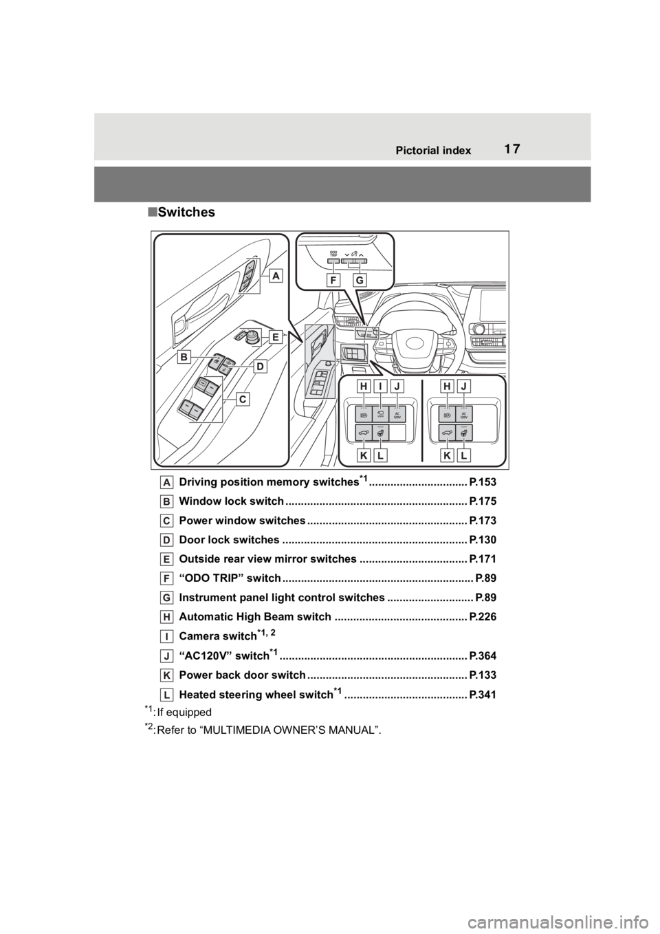
■Switches
Driving position memory switches*1................................ P.153
Window lock switch ............................................. .............. P.175
Power window switches ....... ............................................. P.173
Door lock switches ............................................................ P.130
Outside rear view mirror swi tches ................................... P.171
“ODO TRIP” switch .............................................. ................ P.89
Instrument panel light control switches ........................ .... P.89
Automatic High Beam switch ..................................... ...... P.226
Camera switch
*1, 2
“AC120V” switch*1............................................................. P. 364
Power back door switch ... ................................................. P.133
Heated steering wheel switch
*1........................................ P.341
*1: If equipped
*2: Refer to “MULTIMEDIA OWNER’S MANUAL”.
Page 39 of 572
391-1. For safe use
1
For safety and security
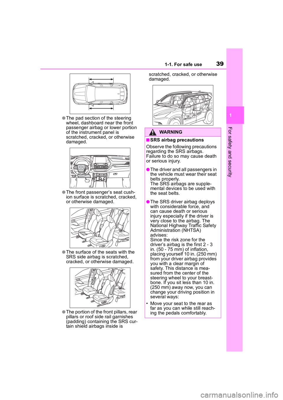
●The pad section of the steering
wheel, dashboard near the front
passenger airbag or lower portion
of the instrument panel is
scratched, cracked, or otherwise
damaged.
●The front passenger’s seat cush-
ion surface is scratched, cracked,
or otherwise damaged.
●The surface of the seats with the
SRS side airbag is scratched,
cracked, or otherwise damaged.
●The portion of the front pillars, rear
pillars or roof side rail garnishes
(padding) containing the SRS cur-
tain shield airbags inside is scratched, cracked, or otherwise
damaged.
WARNING
■SRS airbag precautions
Observe the following precautions
regarding the SRS airbags.
Failure to do so may cause death
or serious injury.
●The driver and all passengers in
the vehicle must wear their seat
belts properly.
The SRS airbags are supple-
mental devices to be used with
the seat belts.
●The SRS driver airbag deploys
with considerable force, and
can cause death or serious
injury especially if the driver is
very close to the airbag. The
National Highway Traffic Safety
Administration (NHTSA)
advises:
Since the risk zone for the
driver’s airbag is the first 2 - 3
in. (50 - 75 mm) of inflation,
placing yourself 10 in. (250 mm)
from your driver airbag provides
you with a clear margin of
safety. This distance is mea-
sured from the c enter of the
steering wheel to your breast-
bone. If you sit less than 10 in.
(250 mm) away now, you can
change your driv ing position in
several ways:
• Move your seat to the rear as far as you can while still reach-
ing the pedals comfortably.
Page 40 of 572
401-1. For safe use
WARNING
• Slightly recline the back of the seat.
Although vehicle designs vary,
many drivers can achieve the
10 in. (250 mm) distance, even
with the driver seat all the way
forward, simply by reclining the
back of the seat somewhat. If
reclining the back of your seat
makes it hard to see the road,
raise yourself by using a firm,
non-slippery cushion, or raise
the seat if your vehicle has that
feature.
• If your steering wheel is adjust- able, tilt it downward. This
points the airbag toward your
chest instead of your head and
neck.
The seat should be adjusted as
recommended by NHTSA above,
while still maintaining control of
the foot pedals, steering wheel,
and your view of the instrument
panel controls.
●If the seat belt extender has
been connected to the front
seat belt buckles but the seat
belt extender has not also been
fastened to the latch plate of the
seat belt, the SRS front airbags
will judge that the driver and
front passenger are wearing the
seat belt even though the seat
belt has not been connected. In
this case, the SRS front airbags
may not activate correctly in a
collision, resulting in death or
serious injury in the event of a
collision. Be su re to wear the
seat belt with the seat belt
extender.
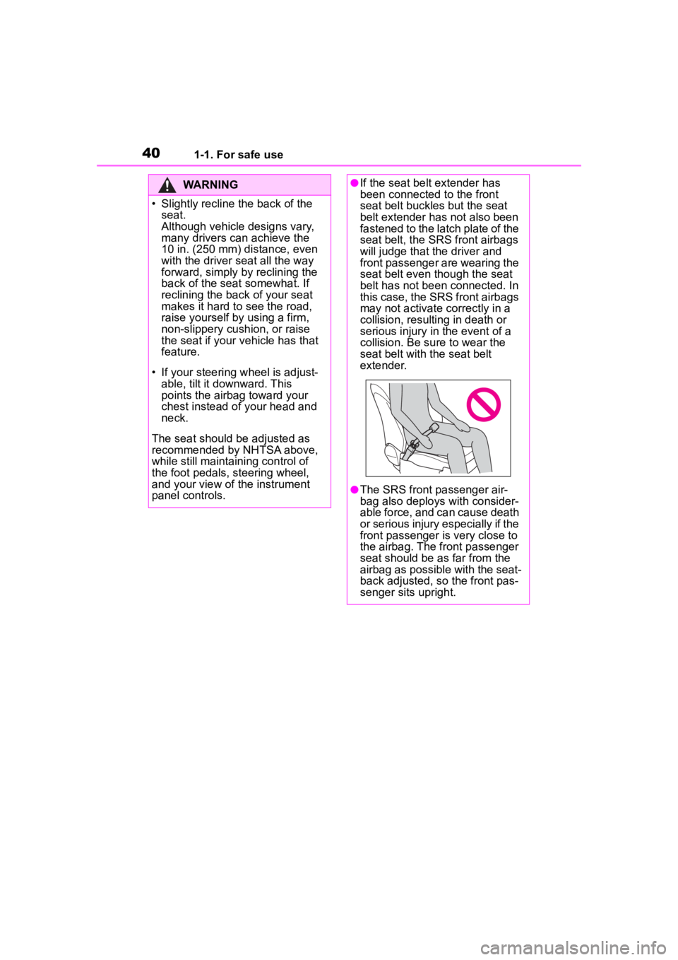
●The SRS front passenger air-
bag also deploys with consider-
able force, and can cause death
or serious injury especially if the
front passenger is very close to
the airbag. The front passenger
seat should be as far from the
airbag as possible with the seat-
back adjusted, so the front pas-
senger sits upright.
Page 41 of 572
411-1. For safe use
1
For safety and security
WARNING
●Improperly seated and/or
restrained infants and children
can be killed or seriously injured
by a deploying airbag. An infant
or child who is too small to use
a seat belt should be properly
secured using a child restraint
system. Toyota strongly recom-
mends that all infants and chil-
dren be placed in the rear seats
of the vehicle and properly
restrained. The rear seats are
safer for infants and children
than the front passenger seat.
(
P. 5 0 )
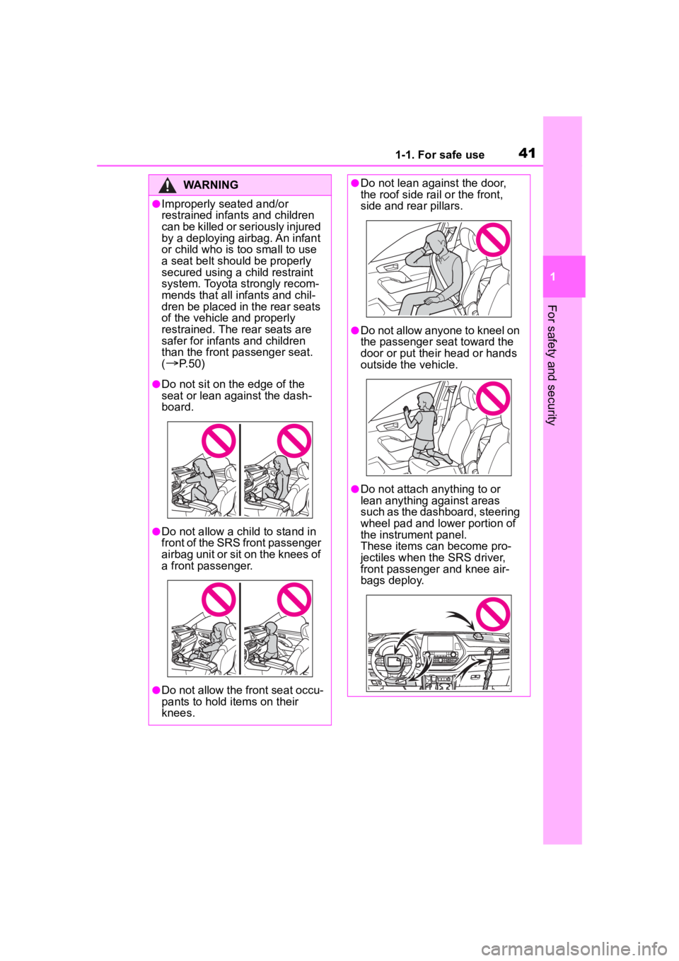
●Do not sit on the edge of the
seat or lean against the dash-
board.
●Do not allow a child to stand in
front of the SRS front passenger
airbag unit or sit on the knees of
a front passenger.
●Do not allow the front seat occu-
pants to hold items on their
knees.
●Do not lean against the door,
the roof side rail or the front,
side and rear pillars.
●Do not allow anyone to kneel on
the passenger seat toward the
door or put their head or hands
outside the vehicle.
●Do not attach anything to or
lean anything against areas
such as the dashboard, steering
wheel pad and lower portion of
the instrument panel.
These items can become pro-
jectiles when th e SRS driver,
front passenger and knee air-
bags deploy.
Page 42 of 572
421-1. For safe use
WARNING
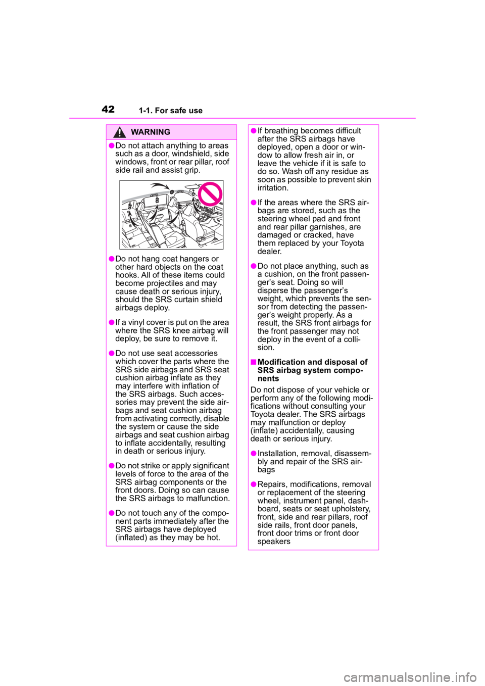
●Do not attach anything to areas
such as a door, windshield, side
windows, front or rear pillar, roof
side rail and assist grip.
●Do not hang coat hangers or
other hard objects on the coat
hooks. All of these items could
become projectiles and may
cause death or serious injury,
should the SRS curtain shield
airbags deploy.
●If a vinyl cover is put on the area
where the SRS knee airbag will
deploy, be sure to remove it.
●Do not use seat accessories
which cover the parts where the
SRS side airbags and SRS seat
cushion airbag inflate as they
may interfere with inflation of
the SRS airbags. Such acces-
sories may prevent the side air-
bags and seat cushion airbag
from activating correctly, disable
the system or cause the side
airbags and seat cushion airbag
to inflate accidentally, resulting
in death or serious injury.
●Do not strike or apply significant
levels of force to the area of the
SRS airbag components or the
front doors. Doing so can cause
the SRS airbags to malfunction.
●Do not touch any of the compo-
nent parts immediately after the
SRS airbags have deployed
(inflated) as they may be hot.
●If breathing becomes difficult
after the SRS airbags have
deployed, open a door or win-
dow to allow fresh air in, or
leave the vehicle if it is safe to
do so. Wash off any residue as
soon as possible to prevent skin
irritation.
●If the areas where the SRS air-
bags are stored, such as the
steering wheel pad and front
and rear pillar garnishes, are
damaged or cracked, have
them replaced by your Toyota
dealer.
●Do not place anything, such as
a cushion, on the front passen-
ger’s seat. Doing so will
disperse the passenger’s
weight, which prevents the sen-
sor from detecting the passen-
ger’s weight properly. As a
result, the SRS front airbags for
the front passenger may not
deploy in the event of a colli-
sion.
■Modification and disposal of
SRS airbag system compo-
nents
Do not dispose of your vehicle or
perform any of the following modi-
fications without consulting your
Toyota dealer. The SRS airbags
may malfunction or deploy
(inflate) accidentally, causing
death or serious injury.
●Installation, re moval, disassem-
bly and repair of the SRS air-
bags
●Repairs, modific ations, removal
or replacement of the steering
wheel, instrument panel, dash-
board, seats or seat upholstery,
front, side and rear pillars, roof
side rails, front door panels,
front door trims or front door
speakers
Page 82 of 572
822-1. Instrument cluster
2-1.Instrument cluster
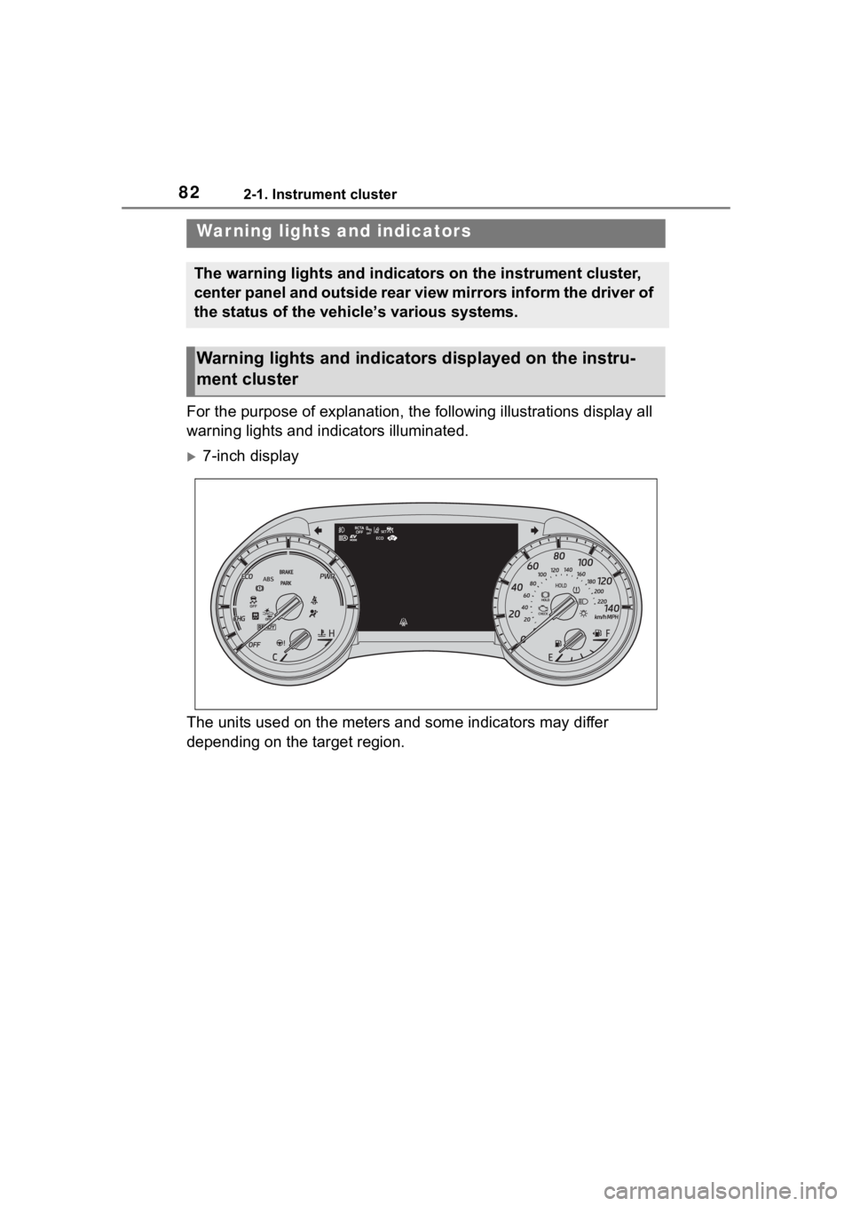
For the purpose of explanation, the following illustrations display all
warning lights and indicators illuminated.
7-inch display
The units used on the meters and some indicators may differ
depending on the target region.
War ning lights and indicators
The warning lights and indicators on the instrument cluster,
center panel and outside rear view mirrors inform the driver of
the status of the vehicle’s various systems.
Warning lights and indicators displayed on the instru-
ment cluster
Page 86 of 572

862-1. Instrument cluster
*4: This light illuminates on the multi-information display.
*5: This light illumi nates on the cen-
ter panel.
*6: When the outside temperature is approximately 37°F (3°C) or
lower, this indicator will flash for
approximately 10 seconds, then
stay on.
*7: Depending on the operating con-dition, the color and illuminat-
ing/flashing state of the light
change.
Page 89 of 572
892-1. Instrument cluster
2
Vehicle status information and indicators
■Display items
Odometer
Displays the total distance the vehi-
cle has been driven.
Trip meter A/trip meter B
Displays the distan ce the vehicle
has been driven si nce the meter
was last reset. Trip meters A and B
can be used to record and display
different distances independently.
■Changing the display
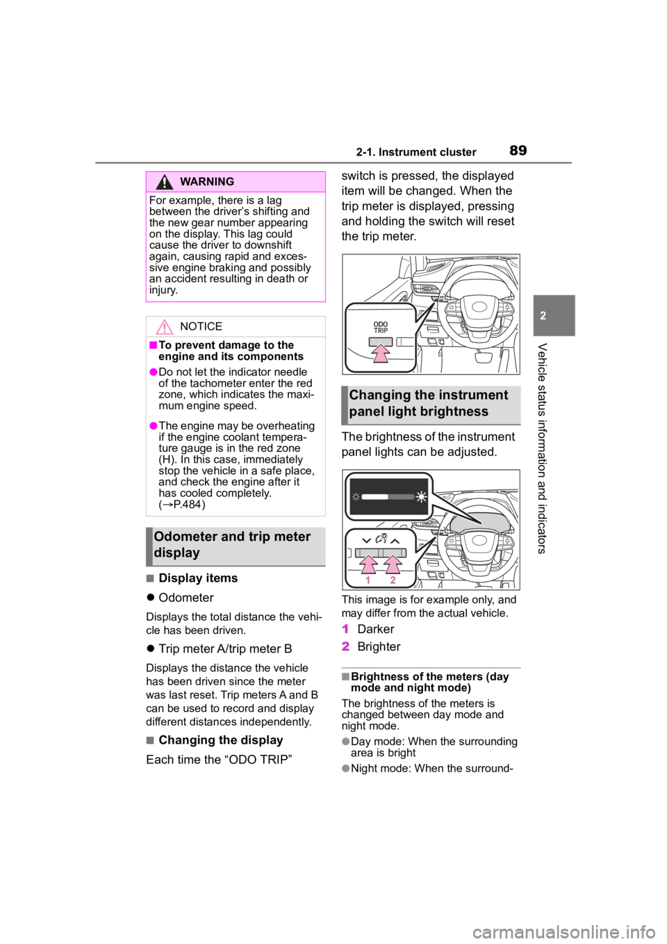
Each time the “ODO TRIP” switch is pressed, the displayed
item will be changed. When the
trip meter is displayed, pressing
and holding the switch will reset
the trip meter.
The brightness of the instrument
panel lights can be adjusted.
This image is for example only, and
may differ from the actual vehicle.
1
Darker
2 Brighter
■Brightness of the meters (day
mode and night mode)
The brightness of the meters is
changed between day mode and
night mode.
●Day mode: When the surrounding
area is bright
●Night mode: When the surround-
WARNING
For example, there is a lag
between the driver’s shifting and
the new gear number appearing
on the display. This lag could
cause the driver to downshift
again, causing rapid and exces-
sive engine braking and possibly
an accident resulting in death or
injury.
NOTICE
■To prevent damage to the
engine and its components
●Do not let the i ndicator needle
of the tachomete r enter the red
zone, which indicates the maxi-
mum engine speed.
●The engine may be overheating
if the engine coolant tempera-
ture gauge is in the red zone
(H). In this case, immediately
stop the vehicle in a safe place,
and check the engine after it
has cooled completely.
( P.484)
Odometer and trip meter
display
Changing the instrument
panel light brightness
Page 96 of 572
962-1. Instrument cluster
nance should be performed
soon or is required is dis-
played.
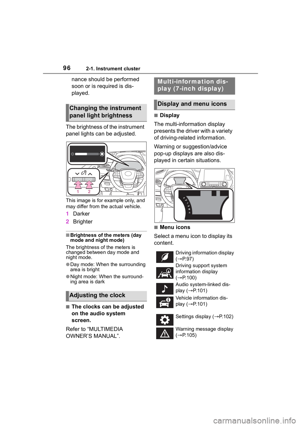
The brightness of the instrument
panel lights can be adjusted.
This image is for example only, and
may differ from the actual vehicle.
1 Darker
2 Brighter
■Brightness of the meters (day
mode and night mode)
The brightness of the meters is
changed between day mode and
night mode.
●Day mode: When the surrounding
area is bright
●Night mode: When the surround-
ing area is dark
■The clocks can be adjusted
on the audio system
screen.
Refer to “MULTIMEDIA
OWNER’S MANUAL”.
■Display
The multi-information display
presents the driver with a variety
of driving-related information.
Warning or suggestion/advice
pop-up displays are also dis-
played in certain situations.
■Menu icons
Select a menu icon to display its
content.
Changing the instrument
panel light brightness
Adjusting the clock
Multi-infor mation dis-
play (7-inch display)
Display and menu icons
Driving information display
( P. 9 7 )
Driving support system
information display
( P.100)
Audio system-linked dis-
play ( P.101)
Vehicle information dis-
play ( P.101)
Settings display ( P.102)
Warning message display
( P.105)