clock TOYOTA HIGHLANDER HYBRID 2023 Owners Manual
[x] Cancel search | Manufacturer: TOYOTA, Model Year: 2023, Model line: HIGHLANDER HYBRID, Model: TOYOTA HIGHLANDER HYBRID 2023Pages: 572, PDF Size: 14.07 MB
Page 87 of 572
872-1. Instrument cluster
2
Vehicle status information and indicators
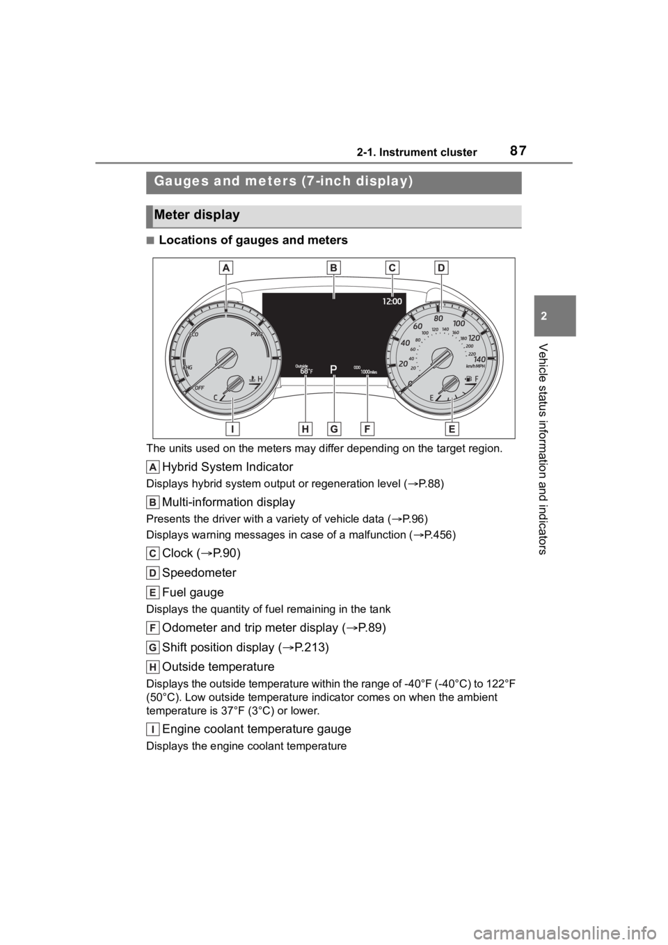
■Locations of gauges and meters
The units used on the meters may differ depending on the target region.
Hybrid System Indicator
Displays hybrid system output or regeneration level ( P. 8 8 )
Multi-information display
Presents the driver with a variety of vehicle data (P.96)
Displays warning messages in case of a malfunction (P.456)
Clock ( P. 9 0 )
Speedometer
Fuel gauge
Displays the quantity of fu el remaining in the tank
Odometer and trip meter display ( P.89)
Shift position display ( P.213)
Outside temperature
Displays the outside temperature within the range of -40°F (-40 °C) to 122°F
(50°C). Low outside temperature indicator comes on when the amb ient
temperature is 37°F (3°C) or lower.
Engine coolant temperature gauge
Displays the engine c oolant temperature
Gauges and meters (7-inch display)
Meter display
Page 90 of 572
902-1. Instrument cluster
ing area is dark
The clocks can be adjusted on
the audio system screen.
Refer to “MULTIMEDIA
OWNER’S MANUAL”.
Adjusting the clock
Page 91 of 572
912-1. Instrument cluster
2
Vehicle status information and indicators
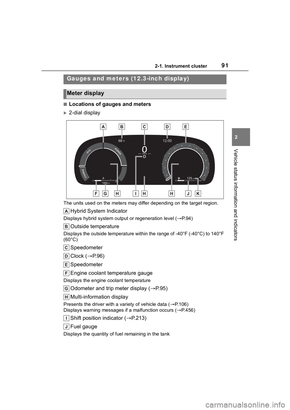
■Locations of gauges and meters
2-dial display
The units used on the meters may differ depending on the target region.
Hybrid System Indicator
Displays hybrid system output or regeneration level ( P. 9 4 )
Outside temperature
Displays the outside temperature within the range of -40°F (-40 °C) to 140°F
(60°C)
Speedometer
Clock ( P. 9 6 )
Speedometer
Engine coolant temperature gauge
Displays the engine c oolant temperature
Odometer and trip meter display ( P.95)
Multi-information display
Presents the driver with a variety of vehicle data (P.106)
Displays warning messages if a malfunction occurs (P.456)
Shift position indicator ( P.213)
Fuel gauge
Displays the quantity of fu el remaining in the tank
Gauges and meters (12.3-inch display)
Meter display
Page 92 of 572
922-1. Instrument cluster
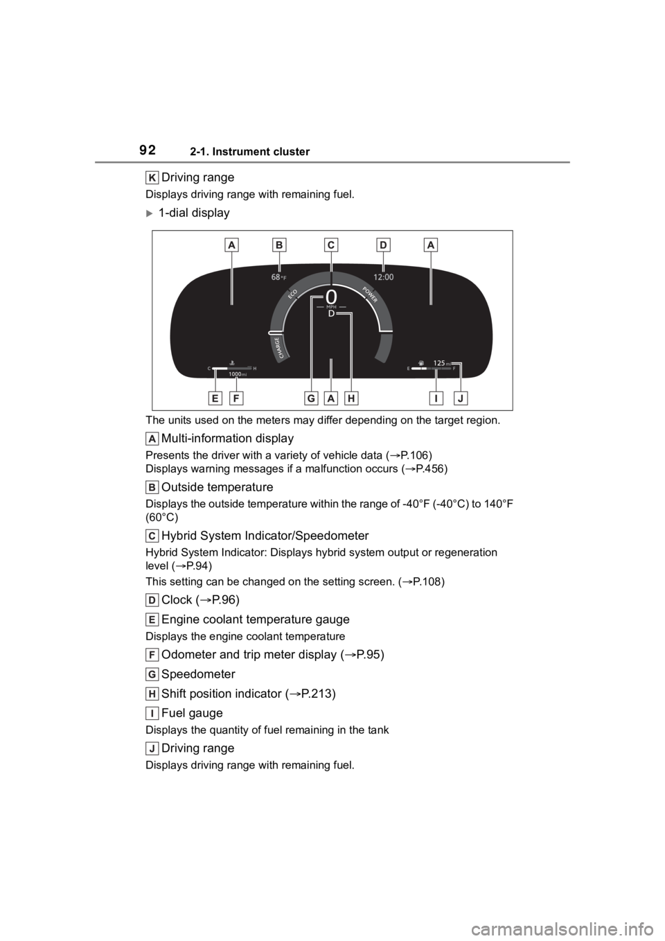
Driving range
Displays driving range with remaining fuel.
1-dial display
The units used on the meters may differ depending on the target region.
Multi-information display
Presents the driver with a variety of vehicle data (P.106)
Displays warning messages if a malfunction occurs (P.456)
Outside temperature
Displays the outside temperature within the range of -40°F (-40 °C) to 140°F
(60°C)
Hybrid System Indicator/Speedometer
Hybrid System Indicator: Display s hybrid system output or regeneration
level ( P. 9 4 )
This setting can be changed on the setting screen. ( P.108)
Clock ( P. 9 6 )
Engine coolant temperature gauge
Displays the engine c oolant temperature
Odometer and trip meter display ( P.95)
Speedometer
Shift position indicator ( P.213)
Fuel gauge
Displays the quantity of fu el remaining in the tank
Driving range
Displays driving range with remaining fuel.
Page 93 of 572
932-1. Instrument cluster
2
Vehicle status information and indicators
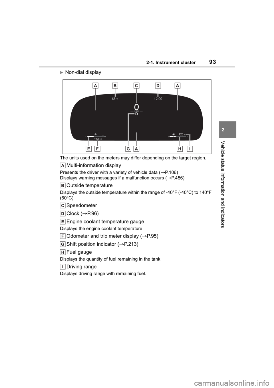
Non-dial display
The units used on the meters may differ depending on the target region.
Multi-information display
Presents the driver with a variety of vehicle data (P.106)
Displays warning messages if a malfunction occurs (P.456)
Outside temperature
Displays the outside temperature within the range of -40°F (-40 °C) to 140°F
(60°C)
Speedometer
Clock ( P. 9 6 )
Engine coolant temperature gauge
Displays the engine c oolant temperature
Odometer and trip meter display ( P.95)
Shift position indicator ( P.213)
Fuel gauge
Displays the quantity of fu el remaining in the tank
Driving range
Displays driving range with remaining fuel.
Page 96 of 572
962-1. Instrument cluster
nance should be performed
soon or is required is dis-
played.
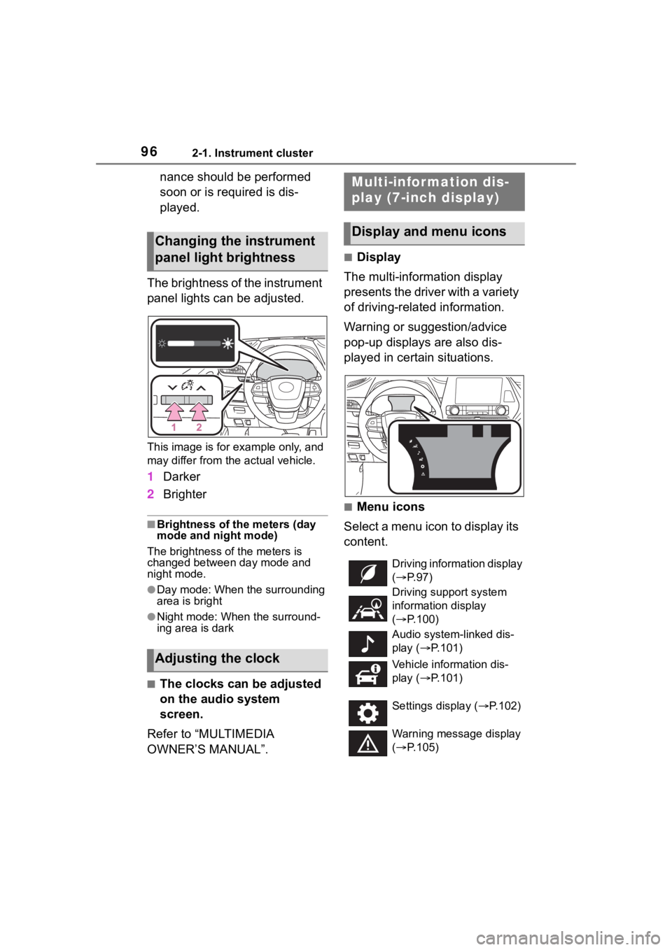
The brightness of the instrument
panel lights can be adjusted.
This image is for example only, and
may differ from the actual vehicle.
1 Darker
2 Brighter
■Brightness of the meters (day
mode and night mode)
The brightness of the meters is
changed between day mode and
night mode.
●Day mode: When the surrounding
area is bright
●Night mode: When the surround-
ing area is dark
■The clocks can be adjusted
on the audio system
screen.
Refer to “MULTIMEDIA
OWNER’S MANUAL”.
■Display
The multi-information display
presents the driver with a variety
of driving-related information.
Warning or suggestion/advice
pop-up displays are also dis-
played in certain situations.
■Menu icons
Select a menu icon to display its
content.
Changing the instrument
panel light brightness
Adjusting the clock
Multi-infor mation dis-
play (7-inch display)
Display and menu icons
Driving information display
( P. 9 7 )
Driving support system
information display
( P.100)
Audio system-linked dis-
play ( P.101)
Vehicle information dis-
play ( P.101)
Settings display ( P.102)
Warning message display
( P.105)
Page 329 of 572
3295-1. Using the air conditioning system and defogger
5
Interior features
■Adjusting the temperature
setting
Turn driver’s side temperature
control switch clockwise to
increases the temperature and
turn the switch counterclockwise
to decreases the temperature.
If “A/C” switch is not pressed, the
system will blow a mbient tempera-
ture air or heated air.
The temperature for the driver,
front passenger and rear seats
can be adjusted separately
when:
“SYNC” control knob is
moved upward or downward.
(The “PASS” and “REAR” dis-
plays disappear)
The passenger’s side tem-
perature control switch is
turned. (The “PASS” display
disappears)
The rear seat temperature
control knob is moved upward
or downward. (The “REAR”
display disappears)
To switch the air c onditioning sys-
tem between individual and simul-
taneous modes, move “SYNC”
control knob upward or downward.
■Setting the fan speed
To set the fan speed, move the
fan speed control knob upward
or downward.
Upward: Increases the fan speed
Downward: Decreases the fan
speed
Pressing the “OFF” switch turns off the fan.
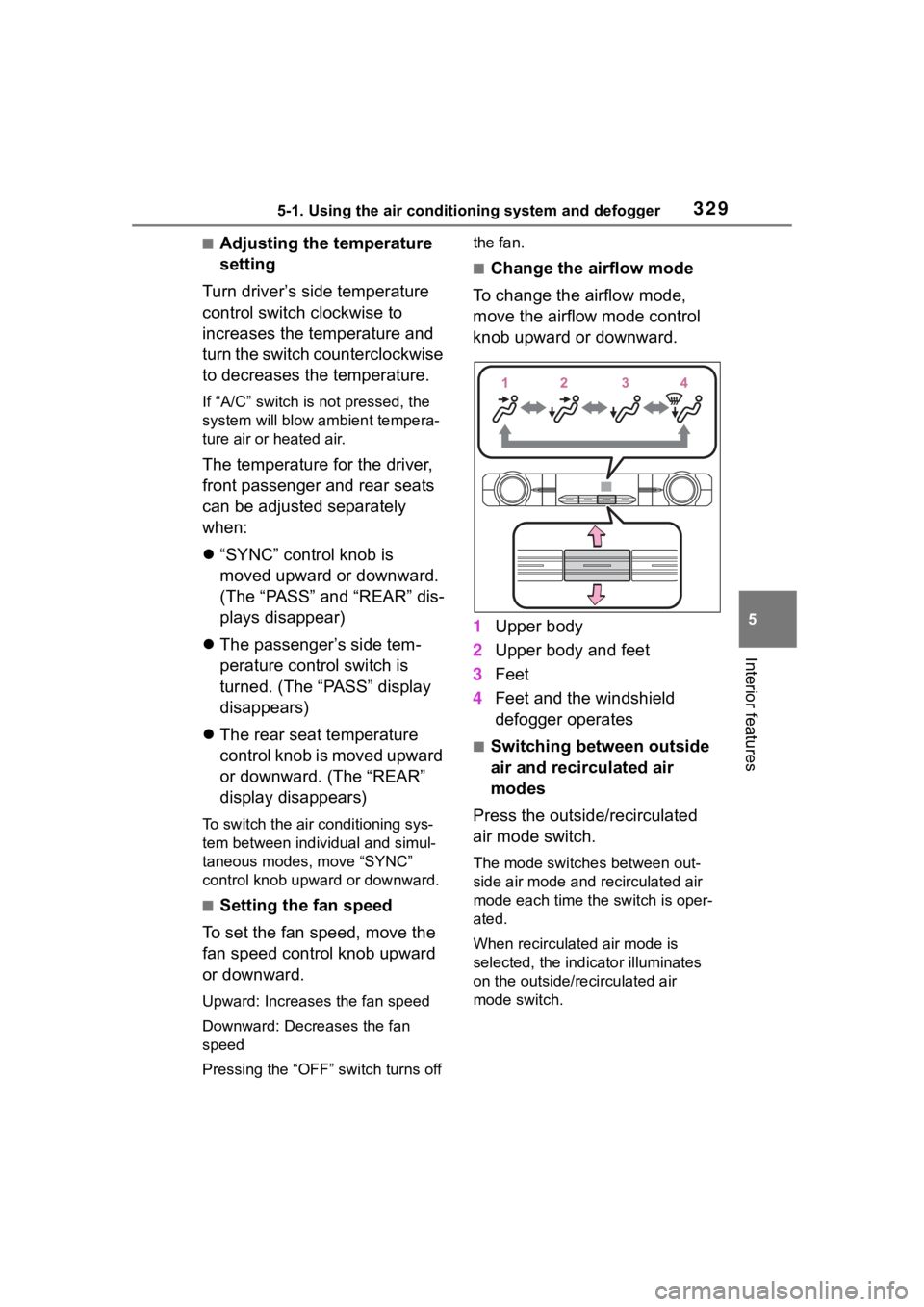
■Change the airflow mode
To change the airflow mode,
move the airflow mode control
knob upward or downward.
1 Upper body
2 Upper body and feet
3 Feet
4 Feet and the windshield
defogger operates
■Switching between outside
air and recirculated air
modes
Press the outside/recirculated
air mode switch.
The mode switches between out-
side air mode and recirculated air
mode each time the switch is oper-
ated.
When recirculated air mode is
selected, the indicator illuminates
on the outside/recirculated air
mode switch.
Page 397 of 572
3976-3. Do-it-yourself maintenance
6
Maintenance and care
stick.
■Checking the engine oil
1 Park the vehicle on level
ground. After warming up the
engine and turning off the
hybrid system, wait more
than 5 minutes for the oil to
drain back into the bottom of
the engine.
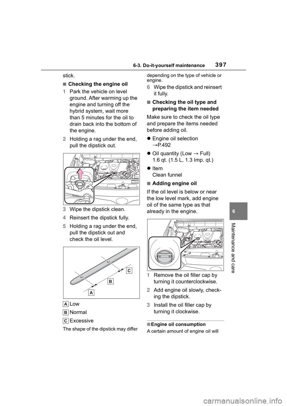
2 Holding a rag under the end,
pull the dipstick out.
3 Wipe the dipstick clean.
4 Reinsert the dipstick fully.
5 Holding a rag under the end,
pull the dipstick out and
check the oil level.
Low
Normal
Excessive
The shape of the dipstick may differ depending on the type of vehicle or
engine.
6
Wipe the dipstick and reinsert
it fully.
■Checking the oil type and
preparing the item needed
Make sure to check the oil type
and prepare the items needed
before adding oil.
Engine oil selection
P.492
Oil quantity (Low Full)
1.6 qt. (1.5 L, 1.3 Imp. qt.)
Item
Clean funnel
■Adding engine oil
If the oil level is below or near
the low level mark, add engine
oil of the same type as that
already in the engine.
1 Remove the oil filler cap by
turning it counterclockwise.
2 Add engine oil slowly, check-
ing the dipstick.
3 Install the oil filler cap by
turning it clockwise.
■Engine oil consumption
A certain amount of engine oil will
Page 430 of 572
4306-3. Do-it-yourself maintenance
on the inside of the lens.
●Water has built up inside the light.
■When replacing light bulbs
P. 4 2 6
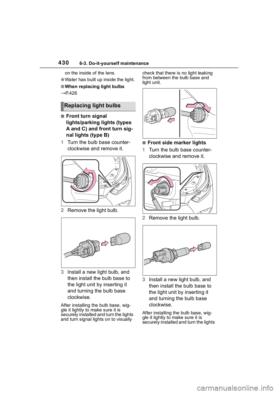
■Front turn signal
lights/parking lights (types
A and C) and front turn sig-
nal lights (type B)
1 Turn the bulb base counter-
clockwise and remove it.
2 Remove the light bulb.
3 Install a new light bulb, and
then install the bulb base to
the light unit by inserting it
and turning the bulb base
clockwise.
After installing th e bulb base, wig-
gle it lightly to make sure it is
securely installed and turn the lights
and turn signal li ghts on to visually check that there is no light leaking
from between the bulb base and
light unit.
■Front side marker lights
1 Turn the bulb base counter-
clockwise and remove it.
2 Remove the light bulb.
3 Install a new light bulb, and
then install the bulb base to
the light unit by inserting it
and turning the bulb base
clockwise.
After installing the bulb base, wig-
gle it lightly to make sure it is
securely installed a nd turn the lights
Replacing light bulbs
Page 431 of 572
4316-3. Do-it-yourself maintenance
6
Maintenance and care
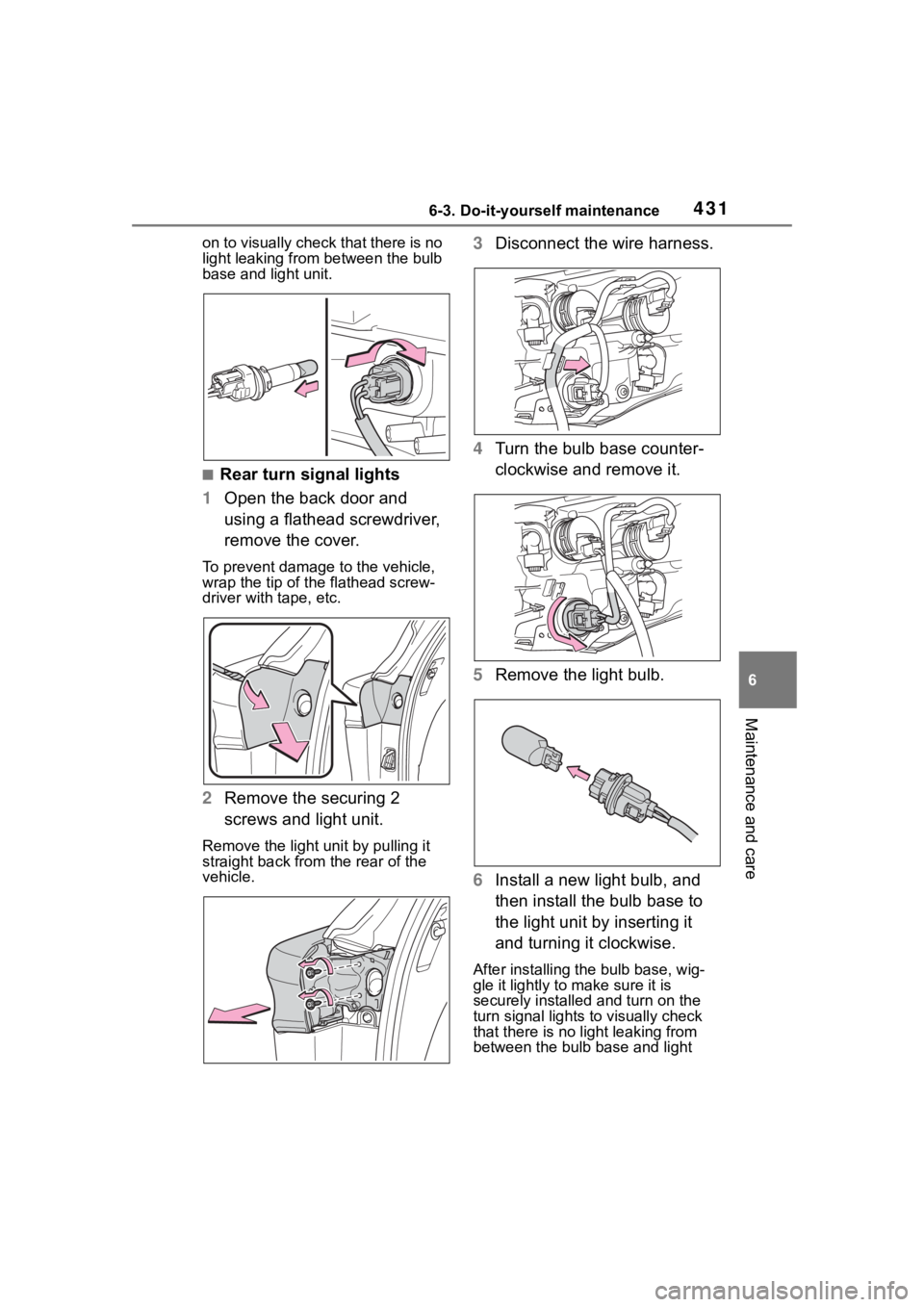
on to visually check that there is no
light leaking from between the bulb
base and light unit.
■Rear turn signal lights
1 Open the back door and
using a flathead screwdriver,
remove the cover.
To prevent damage to the vehicle,
wrap the tip of the flathead screw-
driver with tape, etc.
2Remove the securing 2
screws and light unit.
Remove the light u nit by pulling it
straight back from the rear of the
vehicle.
3 Disconnect the wire harness.
4 Turn the bulb base counter-
clockwise and remove it.
5 Remove the light bulb.
6 Install a new light bulb, and
then install the bulb base to
the light unit by inserting it
and turning it clockwise.
After installing the bulb base, wig-
gle it lightly to make sure it is
securely installed and turn on the
turn signal lights to visually check
that there is no light leaking from
between the bulb base and light