power steering fluid TOYOTA LAND CRUISER 1996 J80 User Guide
[x] Cancel search | Manufacturer: TOYOTA, Model Year: 1996, Model line: LAND CRUISER, Model: TOYOTA LAND CRUISER 1996 J80Pages: 1399, PDF Size: 41.35 MB
Page 1284 of 1399

R08069
R08082
R08066
Soft Jaws
−
STEERING POWER STEERING VANE PUMP
SR−31
1996 LAND CRUISER (RM451U)
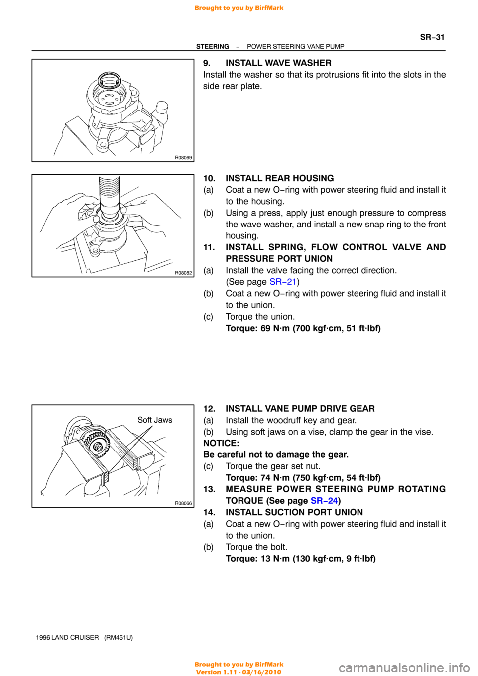
9. INSTALL WAVE WASHER
Install the washer so that its protrusions fit into the slots in the
side rear plate.
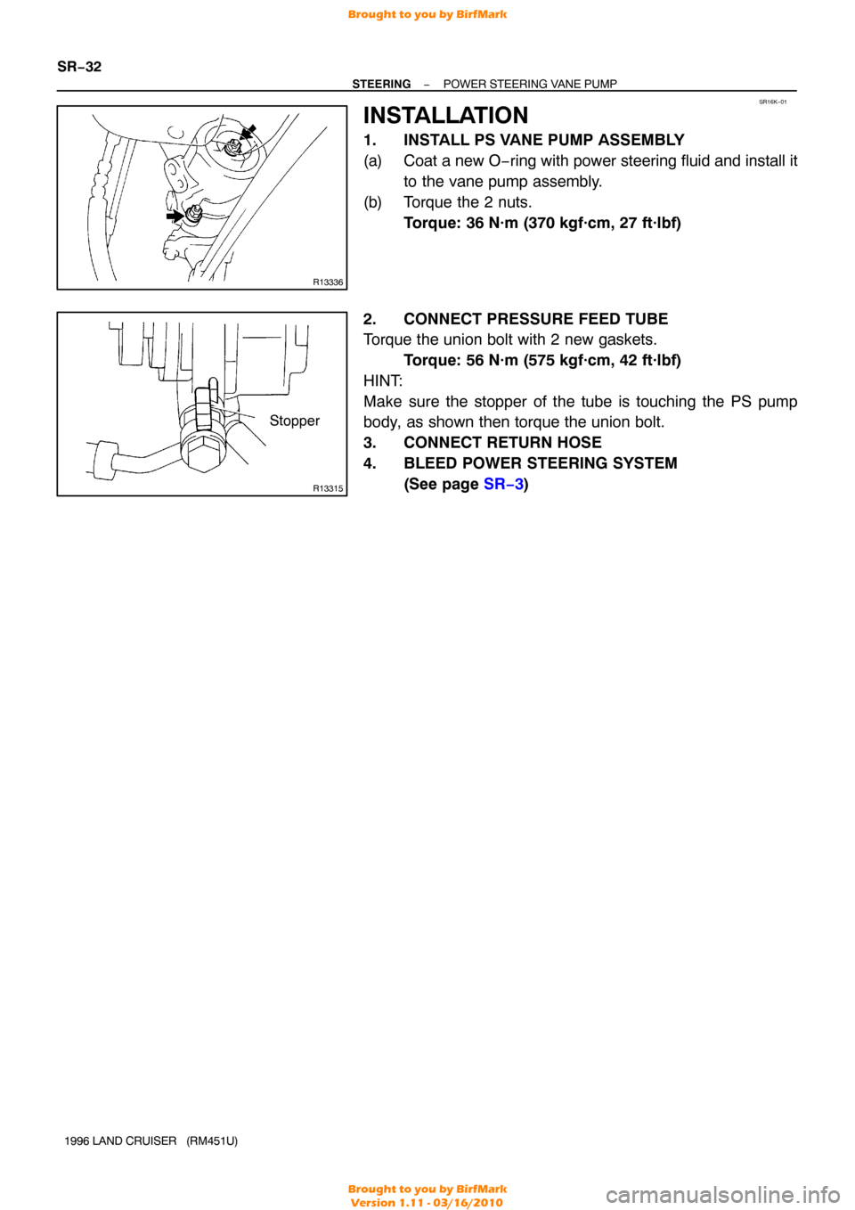
10. INSTALL REAR HOUSING
(a) Coat a new O−ring with power steering fluid and install it
to the housing.
(b) Using a press, apply just enough pressure to compress the wave washer, and install a new snap ring to the front
housing.
11. INSTALL SPRING, FLOW CONTROL VALVE AND PRESSURE PORT UNION
(a) Install the valve facing the correct direction. (See page SR−21 )
(b) Coat a new O −ring with power steering fluid and install it
to the union.
(c) Torque the union. Torque: 69 N·m (700 kgf·cm, 51 ft·lbf)
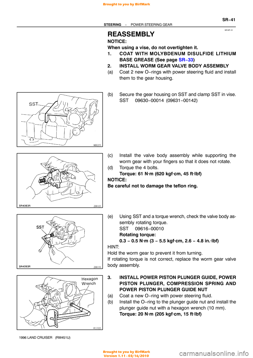
12. INSTALL VANE PUMP DRIVE GEAR
(a) Install the woodruff key and gear.
(b) Using soft jaws on a vise, clamp the gear in the vise.
NOTICE:
Be careful not to damage the gear.
(c) Torque the gear set nut. Torque: 74 N·m (750 kgf·cm, 54 ft·lbf)
13. MEASURE POWER STEERING PUMP ROTATING
TORQUE (See page SR−24 )
14. INSTALL SUCTION PORT UNION
(a) Coat a new O −ring with power steering fluid and install it
to the union.
(b) Torque the bolt.
Torque: 13 N·m (130 kgf·cm, 9 ft·lbf)
Brought to you by BirfMark
Brought to you by BirfMark
Version 1.11 - 03/16/2010
Page 1285 of 1399

SR16K−01
R13336
R13315
Stopper
SR−32
−
STEERING POWER STEERING VANE PUMP
1996 LAND CRUISER (RM451U)
INSTALLATION
1. INSTALL PS VANE PUMP ASSEMBLY
(a) Coat a new O −ring with power steering fluid and install it
to the vane pump assembly.
(b) Torque the 2 nuts. Torque: 36 N·m (370 kgf·cm, 27 ft·lbf)
2. CONNECT PRESSURE FEED TUBE
Torque the union bolt with 2 new gaskets. Torque: 56 N·m (575 kgf·cm, 42 ft·lbf)
HINT:
Make sure the stopper of the tube is touching the PS pump
body, as shown then torque the union bolt.
3. CONNECT RETURN HOSE
4. BLEED POWER STEERING SYSTEM (See page SR−3 )
Brought to you by BirfMark
Brought to you by BirfMark
Version 1.11 - 03/16/2010
Page 1292 of 1399

SR2804
−
STEERING POWER STEERING GEAR
SR−39
1996 LAND CRUISER (RM451U)
(d) Coat a new O− ring and metal spacer with power steering
fluid and install them.
(e) Using snap ring pliers, install a new snap ring.
(f) Coat a new teflon ring with power steering fluid.
(g) Form a teflon ring into a heart shape and install it with
hand.
(h) Using SST, form the teflon ring.
SST 09630−00014 (09631 −00121)
NOTICE:
The teflon ring must be squeezed before inserting the
cross shaft or damage will result.
(i) Coat a new oil seal with power steering fluid.
(j) Using SST, press in the oil seal to the gear housing. SST 09950−60010 (09951 −00340, 09951−00450)
09950 −70010 (09951 −07200)
NOTICE:
Make sure you install the oil seal facing the correct direc-
tion.
5. IF NECESSARY, REPLACE TEFLON RING AND O −
RING
(a) Using a screwdriver, remove the teflon ring and O −ring
from the worm gear valve body assembly.
NOTICE:
Be careful not to damage the worm gear valve body assem-
bly.
(b) Coat a new O −ring with power steering fluid and install it.
(c) Expand a new teflon ring with your fingers.
NOTICE:
Be careful not to overexpand the teflon ring.
(d) Install the teflon ring.
(e) Coat the teflon ring with power steering fluid and snug it down with piston ring compressor for 5 − 7 minutes.
Brought to you by BirfMark
Brought to you by BirfMark
Version 1.11 - 03/16/2010
Page 1294 of 1399

SR16P−01
−
STEERING POWER STEERING GEAR
SR−41
1996 LAND CRUISER (RM451U)
REASSEMBLY
NOTICE:
When using a vise, do not overtighten it.
1. COAT WITH MOLYBDENUM DISULFIDE LITHIUM
BASE GREASE (See page SR−33 )
2. INSTALL WORM GEAR VALVE BODY ASSEMBLY
(a) Coat 2 new O−rings with power steering fluid and install them to the gear housing.
(b) Secure the gear housing on SST and clamp SST in vise. SST 09630−00014 (09631 −00142)
(c) Install the valve body assembly while supporting the worm gear with your fingers so that it does not rotate.
(d) Torque the 4 bolts. Torque: 61 N·m (620 kgf·cm, 45 ft·lbf)
NOTICE:
Be careful not to damage the teflon ring.
(e) Using SST and a torque wrench, check the valve body as-
sembly rotating torque.
SST 09616−00010
Rotating torque:
0.3 − 0.5 N·m (3 − 5.5 kgf·cm, 2.6 − 4.8 in.·lbf)
HINT:
Hold the worm gear to prevent it from turning.
If rotating torque is not correct, replace the worm gear valve
body assembly.
3. INSTALL POWER PISTON PLUNGER GUIDE, POWER
PISTON PLUNGER, COMPRESSION SPRING AND
POWER PISTON PLUNGER GUIDE NUT
(a) Coat a new O−ring with power steering fluid.
(b) Install the O−ring to the plunger guide nut and install the plunger guide nut with a hexagon wrench (10 mm).
Torque: 20 N·m (205 kgf·cm, 15 ft·lbf)
Brought to you by BirfMark
Brought to you by BirfMark
Version 1.11 - 03/16/2010
Page 1295 of 1399

SR−42
−
STEERING POWER STEERING GEAR
1996 LAND CRUISER (RM451U)
4. DETERMINE CENTER POSITION
(a) Using SST, turn the worm gear valve body shaft so full
lock in both directions and determine the exact center.
SST 09616−00010
(b) Place matchmarks on the worm gear valve body shaft and
worm gear valve body housing to show neutral position.
5. INSTALL CROSS SHAFT AND SIDE COVER
(a) Coat a new O −ring with power steering fluid and install it
on the side cover.
(b) Assemble the cross shaft to the side cover.
HINT:
Fully loosen the cross shaft adjusting screw.
(c) Install and push the cross shaft into the gear housing so that the center teeth mesh together.
(d) Torque the 4 bolts in a diagonal pattern. Torque: 61 N·m (620 kgf·cm, 45 ft·lbf)
6. ADJUST TOTAL PRELOAD
(a) Install SST with a torque wrench on the worm gear valve body shaft.
SST 09616−00010
(b) Turn the cross shaft adjusting screw until the preload is
within specification.
Preload (Turning):
0.74 − 10.8 N·m (7.5 − 11.0 kgf·cm, 6.5 − 9.6 in.·lbf)
7. INSTALL NEW SEAL WASHER
8. INSTALL ADJUSTING SCREW LOCK NUT
Torque the lock nut while holding the cross shaft adjusting
screw. Torque: 46 N·m (470 kgf·cm, 34 ft·lbf)
9. CHECK TOTAL PRELOAD
Using SST and a torque wrench, check total preload. SST 09616−00010
Total preload (Turning):
0.74 − 1.08 N·m (7.5 − 11.0 kgf·cm, 6.5 − 9.6 in.·lbf)
Brought to you by BirfMark
Brought to you by BirfMark
Version 1.11 - 03/16/2010