flat tire TOYOTA LAND CRUISER 2013 J200 Service Manual
[x] Cancel search | Manufacturer: TOYOTA, Model Year: 2013, Model line: LAND CRUISER, Model: TOYOTA LAND CRUISER 2013 J200Pages: 720, PDF Size: 21.46 MB
Page 643 of 720
5
When trouble arises
643 5-2. Steps to take in an emergency
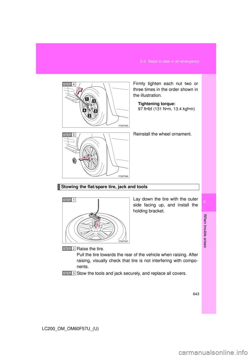
LC200_OM_OM60F57U_(U)Firmly tighten each nut two or
three times in the order shown in
the illustration.
Tightening torque:
97 ft•lbf (131 N•m, 13.4 kgf•m)
Reinstall the wheel ornament.
Stowing the flat/spare tire, jack and tools
Lay down the tire with the outer
side facing up, and install the
holding bracket.
Raise the tire.
Pull the tire towards the rear of the vehicle when raising. After
raising, visually check that tire is not interfering with compo-
nents.
Stow the tools and jack securely, and replace all covers.
STEP4
STEP5
STEP1
STEP2
STEP3
Page 644 of 720
644 5-2. Steps to take in an emergency
LC200_OM_OM60F57U_(U)
■After completing the tire change
The tire pressure warning system must be reset. (P. 545)
CAUTION
■Using the tire jack
Improper use of the tire jack may lead to death or serious injuries due to
the vehicle suddenly falling off the jack.
●Do not use the tire jack for any purpose other than replacing tires or
installing and removing tire chains.
●Only use the tire jack that comes with this vehicle for replacing a flat
tire.
Do not use it on other vehicles, and do not use other tire jacks for
replacing tires on this vehicle.
●Always check that the tire jack is securely set to the jack point.
●Do not raise the vehicle while someone is in it.
●When raising the vehicle, do not put an object on or under the jack.
●Do not raise the vehicle to a height greater than that required to
replace the tire.
●Use a jack stand if it is necessary to get under the vehicle.
●Do not put any part of your body under the vehicle supported by a jack.
●Do not start or run the engine while your vehicle is supported by the
jack.
Take particular care when lowering the vehicle to ensure that no one
working on or near the vehicle may be injured.
■Using the jack handle
Tighten all the jack handle bolts securely using a Phillips-head screw-
driver, to prevent the extension parts from coming apart unexpectedly.
Page 645 of 720
5
When trouble arises
645 5-2. Steps to take in an emergency
LC200_OM_OM60F57U_(U)
CAUTION
■Replacing a flat tire
●Observe the following precautions.
Failure to do so may result in serious injury:
• Lower the spare tire completely to the ground before removing it
from under the vehicle.
• Do not try to remove the wheel ornament by hand. Take due care in
handling the ornament to avoid unexpected personal injury.
• Do not touch the disc wheels or the area around the brakes imme-
diately after the vehicle has been driven.
After the vehicle has been driven the disc wheels and the area
around the brakes will be extremely hot. Touching these areas with
hands, feet or other body parts while changing a tire, etc. may
result in burns.
●Failure to follow these precautions could cause the wheel nuts to
loosen and the tire to fall off, resulting in death or serious injury.
• Have the wheel nuts tightened with a torque wrench to 97 ft•lbf
(131 N•m, 13.4 kgf•m) as soon as possible after changing wheels.
• When installing a tire, only use wheel nuts that have been specifi-
cally designed for that wheel.
• If there are any cracks or deformations in the bolt screws, nut
threads or bolt holes of the wheel, have the vehicle inspected by
your Toyota dealer.
• Do not attach a heavily damaged wheel ornament, as it may fly off
the wheel while the vehicle is moving.
• When installing the wheel nuts, be sure to install them with the
tapered ends facing inward.
(P. 558)
Page 646 of 720

646 5-2. Steps to take in an emergency
LC200_OM_OM60F57U_(U)
NOTICE
■Do not drive the vehicle with a flat tire
Do not continue driving with a flat tire.
Driving even a short distance with a flat tire can damage the tire and the
wheel beyond repair.
■When stowing the flat tire
Ensure that there is no object caught between the tire and the vehicle
underbody.
■When replacing the tires
When removing or fitting the wheels, tires or the tire pressure warning
valve and transmitter, contact your Toyota dealer as the tire pressure
warning valve and transmitter may be damaged if not handled correctly.
■To avoid damage to the tire pressure warning valves and transmit-
ters
When a tire is repaired with liquid sealants, the tire pressure warning
valve and transmitter may not operate properly. If a liquid sealant is
used, contact your Toyota dealer or other qualified service shop as soon
as possible. Make sure to replace the tire pressure warning valve and
transmitter when replacing the tire.
(P. 545)
Page 674 of 720
674 6-1. Specifications
LC200_OM_OM60F57U_(U)
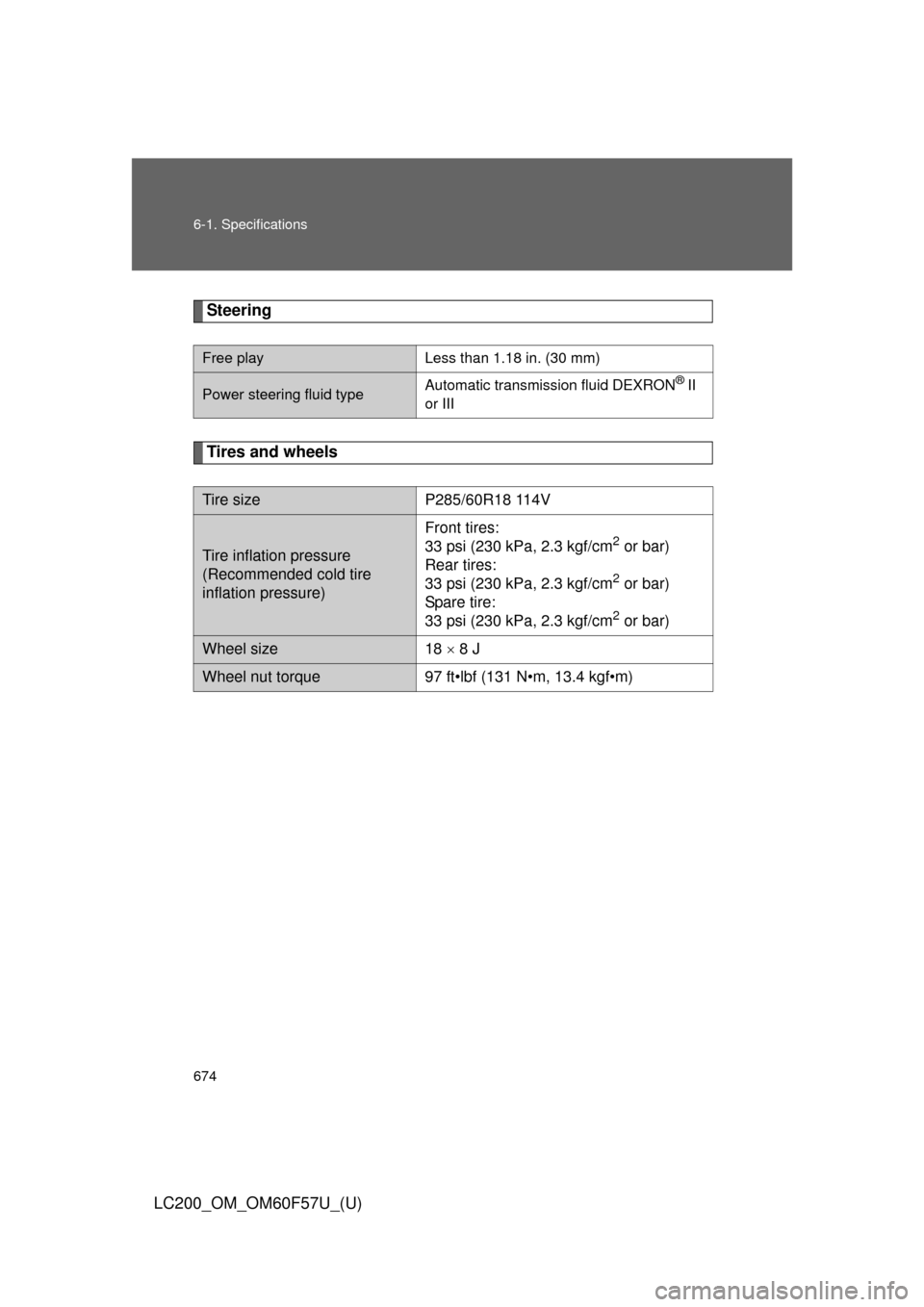
Steering
Tires and wheels
Free playLess than 1.18 in. (30 mm)
Power steering fluid typeAutomatic transmission fluid DEXRON® II
or III
Tire sizeP285/60R18 114V
Tire inflation pressure
(Recommended cold tire
inflation pressure)
Front tires:
33 psi (230 kPa, 2.3 kgf/cm2 or bar)
Rear tires:
33 psi (230 kPa, 2.3 kgf/cm
2 or bar)
Spare tire:
33 psi (230 kPa, 2.3 kgf/cm
2 or bar)
Wheel size18 8 J
Wheel nut torque97 ft•lbf (131 N•m, 13.4 kgf•m)
Page 680 of 720
680
6-1. Specifications
LC200_OM_OM60F57U_(U)
Tire infor mation
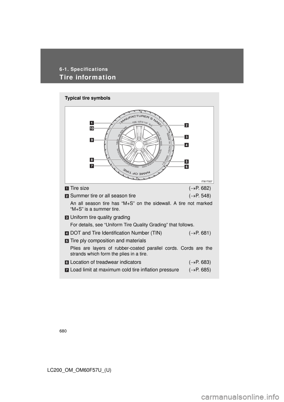
Typical tire symbols
Tire size (P. 682)
Summer tire or all season tire (P. 548)
An all season tire has “M+S” on the sidewall. A tire not marked
“M+S” is a summer tire.
Uniform tire quality grading
For details, see “Uniform Tire Quality Grading” that follows.
DOT and Tire Identification Number (TIN) (P. 681)
Tire ply composition and materials
Plies are layers of rubber-coated parallel cords. Cords are the
strands which form the plies in a tire.
Location of treadwear indicators (P. 683)
Load limit at maximum cold tire inflation pressure (P. 685)
PRIES TREAD : 2 POLYESTER+2STEEL+1NYLON SIDE WALL : 2 POLYESTER
TREADVEAR XXX TRACTION X TEMPERATURE X
TUBELESS STEEL BELTED RADIAL
DOT XXXX XXXX XXXXXXX
P285 / 60R18 114V M+S
STANDARD LOAD MAX.LOAD XXX KG (XXXX LBS) MAX.PRESS. XXX KPA (XXPSI)
Page 681 of 720
681 6-1. Specifications
6
Vehicle specifications
LC200_OM_OM60F57U_(U)
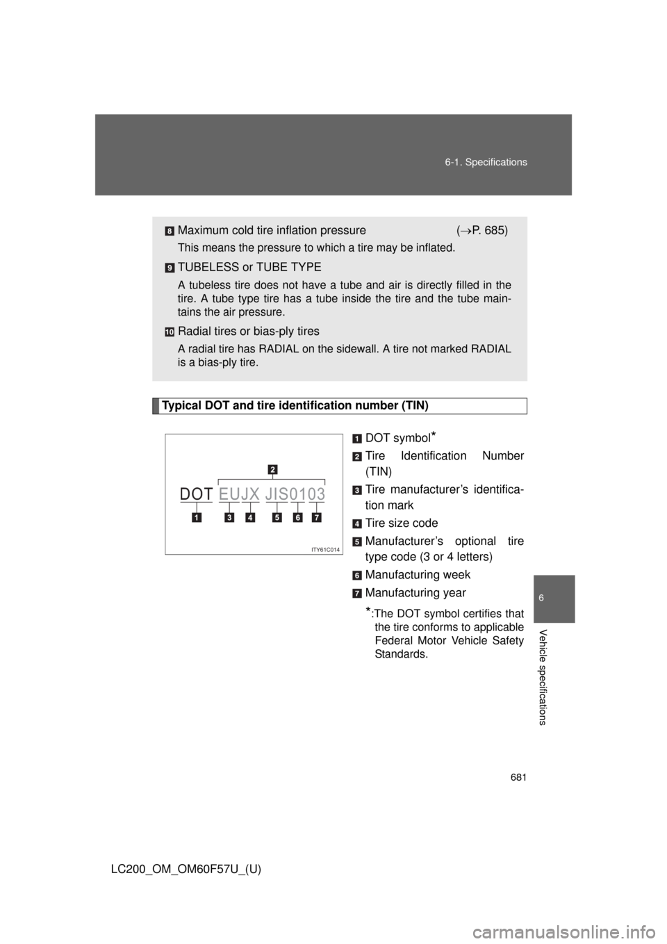
Typical DOT and tire identification number (TIN)
DOT symbol
*
Tire Identification Number
(TIN)
Tire manufacturer’s identifica-
tion mark
Tire size code
Manufacturer’s optional tire
type code (3 or 4 letters)
Manufacturing week
Manufacturing year
*:The DOT symbol certifies that
the tire conforms to applicable
Federal Motor Vehicle Safety
Standards.
Maximum cold tire inflation pressure (P. 685)
This means the pressure to which a tire may be inflated.
TUBELESS or TUBE TYPE
A tubeless tire does not have a tube and air is directly filled in the
tire. A tube type tire has a tube inside the tire and the tube main-
tains the air pressure.
Radial tires or bias-ply tires
A radial tire has RADIAL on the sidewall. A tire not marked RADIAL
is a bias-ply tire.
ITY61C014
DOT EUJX JIS0103
Page 685 of 720
685 6-1. Specifications
6
Vehicle specifications
LC200_OM_OM60F57U_(U)
Warning: The temperature grades for this tire are established for a
tire that is properly inflated and not overloaded.
Excessive speed, underinflation, or excessive loading, either sepa-
rately or in combination, can cause heat buildup and possible tire fail-
ure.
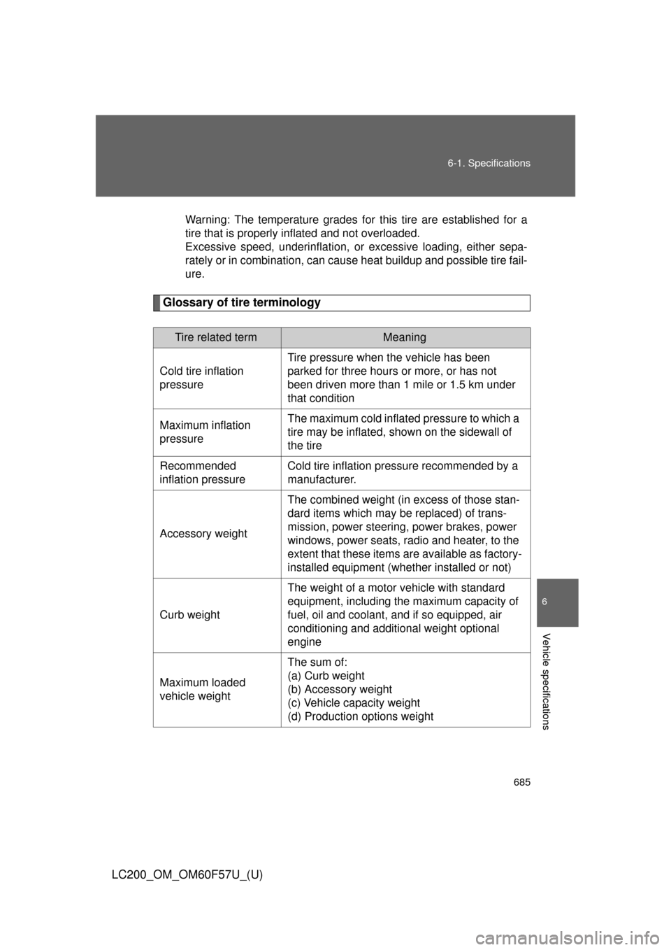
Glossary of tire terminology
Tire related termMeaning
Cold tire inflation
pressureTire pressure when the vehicle has been
parked for three hours or more, or has not
been driven more than 1 mile or 1.5 km under
that condition
Maximum inflation
pressureThe maximum cold inflated pressure to which a
tire may be inflated, shown on the sidewall of
the tire
Recommended
inflation pressureCold tire inflation pressure recommended by a
manufacturer.
Accessory weightThe combined weight (in excess of those stan-
dard items which may be replaced) of trans-
mission, power steering, power brakes, power
windows, power seats, radio and heater, to the
extent that these items are available as factory-
installed equipment (whether installed or not)
Curb weightThe weight of a motor vehicle with standard
equipment, including the maximum capacity of
fuel, oil and coolant, and if so equipped, air
conditioning and additional weight optional
engine
Maximum loaded
vehicle weightThe sum of:
(a) Curb weight
(b) Accessory weight
(c) Vehicle capacity weight
(d) Production options weight
Page 687 of 720
687 6-1. Specifications
6
Vehicle specifications
LC200_OM_OM60F57U_(U)
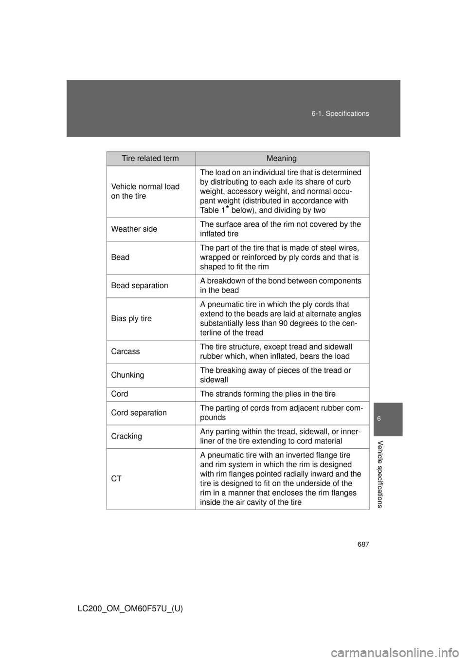
Tire related termMeaning
Vehicle normal load
on the tireThe load on an individual tire that is determined
by distributing to each axle its share of curb
weight, accessory weight, and normal occu-
pant weight (distributed in accordance with
Ta b l e 1
* below), and dividing by two
Weather sideThe surface area of the rim not covered by the
inflated tire
BeadThe part of the tire that is made of steel wires,
wrapped or reinforced by ply cords and that is
shaped to fit the rim
Bead separationA breakdown of the bond between components
in the bead
Bias ply tireA pneumatic tire in which the ply cords that
extend to the beads are laid at alternate angles
substantially less than 90 degrees to the cen-
terline of the tread
CarcassThe tire structure, except tread and sidewall
rubber which, when inflated, bears the load
ChunkingThe breaking away of pieces of the tread or
sidewall
Cord The strands forming the plies in the tire
Cord separationThe parting of cords from adjacent rubber com-
pounds
CrackingAny parting within the tread, sidewall, or inner-
liner of the tire extending to cord material
CTA pneumatic tire with an inverted flange tire
and rim system in which the rim is designed
with rim flanges pointed radially inward and the
tire is designed to fit on the underside of the
rim in a manner that encloses the rim flanges
inside the air cavity of the tire
Page 688 of 720

688 6-1. Specifications
LC200_OM_OM60F57U_(U)
Tire related termMeaning
Extra load tireA tire designed to operate at higher loads and
at higher inflation pressures than the corre-
sponding standard tire
Groove The space between two adjacent tread ribs
InnerlinerThe layer(s) forming the inside surface of a
tubeless tire that contains the inflating medium
within the tire
Innerliner separationThe parting of the innerliner from cord material
in the carcass
Intended outboard
sidewall(a)The sidewall that contains a whitewall, bears
white lettering, or bears manufacturer, brand,
and/or model name molding that is higher or
deeper than the same molding on the other
sidewall of the tire, or
(b)The outward facing sidewall of asymmetrical
tire that has a particular side that must always
face outward when mounted on a vehicle
Light truck (LT) tireA tire designated by its manufacturer as prima-
rily intended for use on lightweight trucks or
multipurpose passenger vehicles
Load ratingThe maximum load that a tire is rated to carry
for a given inflation pressure
Maximum load ratingThe load rating for a tire at the maximum per-
missible inflation pressure for that tire
Maximum permissible
inflation pressureThe maximum cold inflation pressure to which
a tire may be inflated
Measuring rimThe rim on which a tire is fitted for physical
dimension requirements
Open spliceAny parting at any junction of tread, sidewall, or
innerliner that extends to cord material
Outer diameter The overall diameter of an inflated new tire