TOYOTA LAND CRUISER 2014 J200 Owners Manual
LAND CRUISER 2014 J200
TOYOTA
TOYOTA
https://www.carmanualsonline.info/img/14/6500/w960_6500-0.png
TOYOTA LAND CRUISER 2014 J200 Owners Manual
Trending: light, fuel additives, child lock, dimensions, low beam, airbag, fuel tank capacity
Page 261 of 724
261
2-4. Using other
driving systems
2
When driving
LC200_OM_OM60L09U_(U)
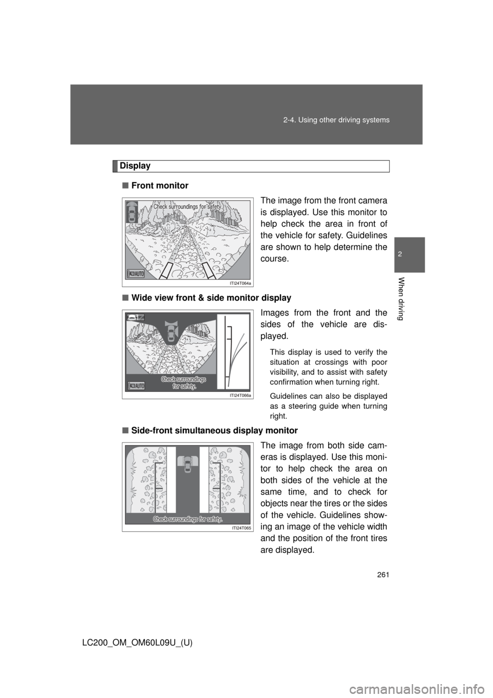
Display
■ Front monitor
The image from the front camera
is displayed. Use this monitor to
help check the area in front of
the vehicle for safety. Guidelines
are shown to help determine the
course.
■ Wide view front & side monitor display
Images from the front and the
sides of the vehicle are dis-
played.
This display is used to verify the
situation at crossings with poor
visibility, and to assist with safety
confirmation when turning right.
Guidelines can also be displayed
as a steering guide when turning
right.
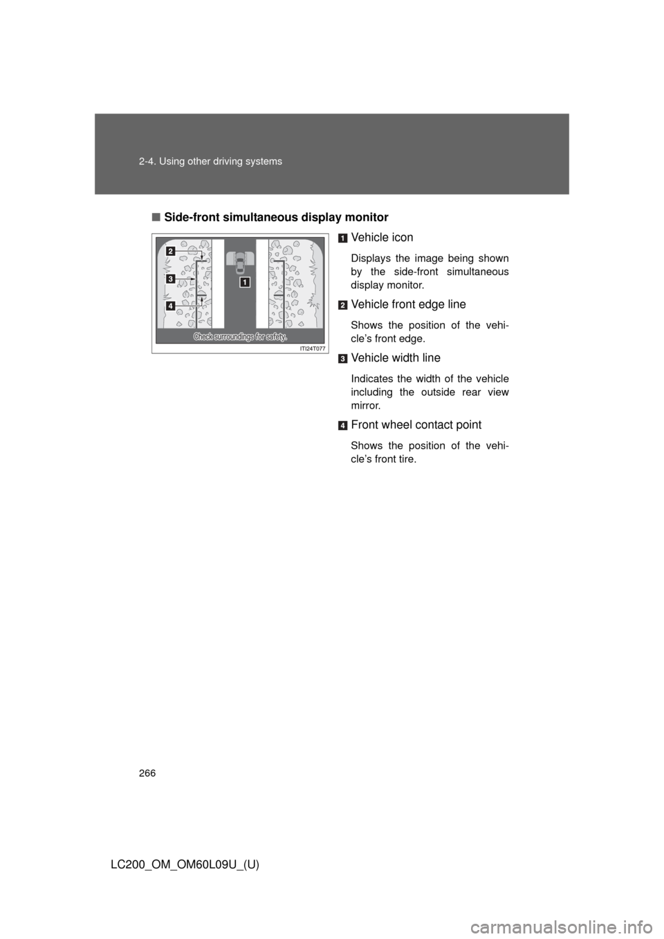
■Side-front simultaneous display monitor
The image from both side cam-
eras is displayed. Use this moni-
tor to help check the area on
both sides of the vehicle at the
same time, and to check for
objects near the tires or the sides
of the vehicle. Guidelines show-
ing an image of the vehicle width
and the position of the front tires
are displayed.
Page 262 of 724
262 2-4. Using other driving systems
LC200_OM_OM60L09U_(U)■
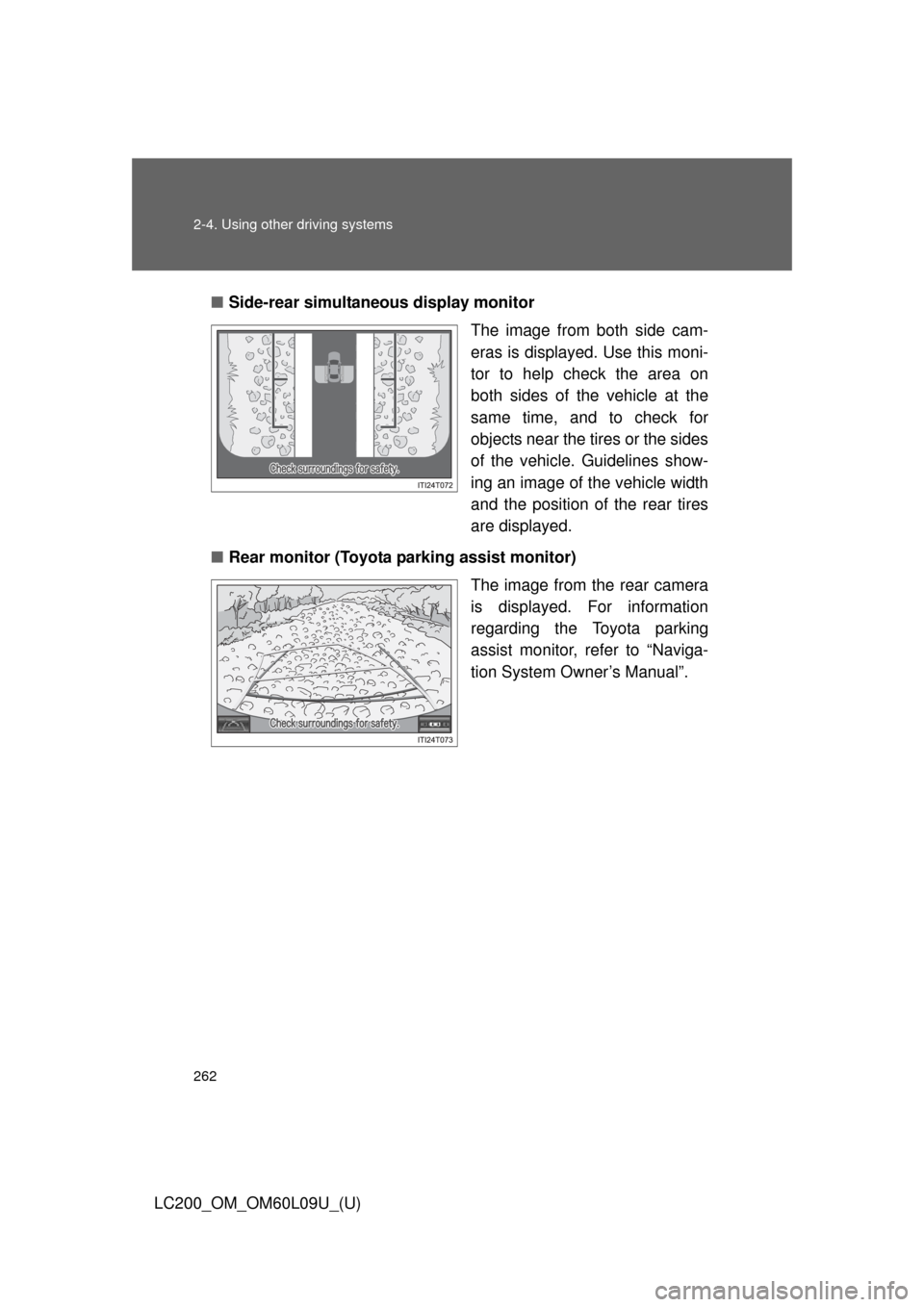
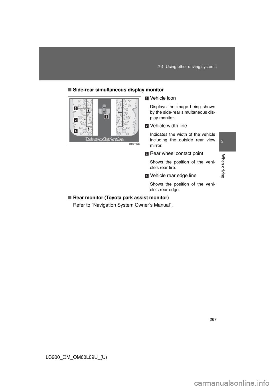
Side-rear simultane ous display monitor
The image from both side cam-
eras is displayed. Use this moni-
tor to help check the area on
both sides of the vehicle at the
same time, and to check for
objects near the tires or the sides
of the vehicle. Guidelines show-
ing an image of the vehicle width
and the position of the rear tires
are displayed.
■ Rear monitor (Toyota parking assist monitor)
The image from the rear camera
is displayed. For information
regarding the Toyota parking
assist monitor, refer to “Naviga-
tion System Owner’s Manual”.
Page 263 of 724
263
2-4. Using other
driving systems
2
When driving
LC200_OM_OM60L09U_(U)
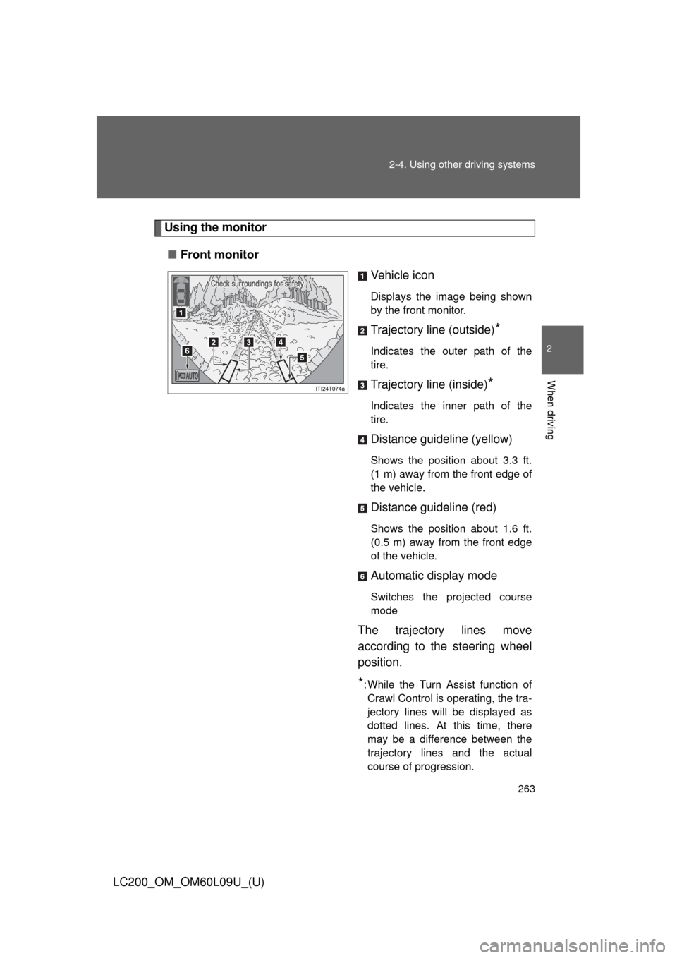
Using the monitor
■ Front monitor
Vehicle icon
Displays the image being shown
by the front monitor.
Trajectory line (outside)*
Indicates the outer path of the
tire.
Trajectory line (inside)*
Indicates the inner path of the
tire.
Distance guideline (yellow)
Shows the position about 3.3 ft.
(1 m) away from the front edge of
the vehicle.
Distance guideline (red)
Shows the position about 1.6 ft.
(0.5 m) away from the front edge
of the vehicle.
Automatic display mode
Switches the projected course
mode
The trajectory lines move
according to the steering wheel
position.
*: While the Turn Assist function ofCrawl Control is operating, the tra-
jectory lines will be displayed as
dotted lines. At this time, there
may be a difference between the
trajectory lines and the actual
course of progression.
Page 264 of 724
264 2-4. Using other driving systems
LC200_OM_OM60L09U_(U)
Wide view front & side monitor displayProjected course line switch-
ing button
The course line display mode will
change as follows each time the
switch is touched.
When the shift lever is in “R”, dis-
play mode can not be changed.
Vehicle icon
Displays the image being shown
by the front monitor.
Front wheel contact point
Shows the position of the vehi-
cle’s front tire.
Vehicle front edge line
Shows the position of the vehi-
cle’s leading edge.
Projected course line (yellow)
Displays a rough guide of the
vehicle path that moves accord-
ing to the steering wheel position.
Displayed along with the mini-
mum projected turning circle.
Page 265 of 724
265
2-4. Using other
driving systems
2
When driving
LC200_OM_OM60L09U_(U) Minimum projected turning cir-
cle (blue)
Displays the smallest turning cir-
cle projected by the system if the
steering wheel is turned to full
lock. Displayed when the steering
wheel is turned to the right (fur-
ther than 90
from straight
ahead).
Vehicle width line (blue)
Indicates the width of the vehicle
including the outside rear view
mirror.
Rear wheel contact point
Shows the position of the vehi-
cle’s rear tire.
Automatic display mode
Switches the projected course
mode
Page 266 of 724
266 2-4. Using other driving systems
LC200_OM_OM60L09U_(U)■
Side-front simultaneous display monitor
Vehicle icon
Displays the image being shown
by the side-front simultaneous
display monitor.
Vehicle front edge line
Shows the position of the vehi-
cle’s front edge.
Vehicle width line
Indicates the width of the vehicle
including the outside rear view
mirror.
Front wheel contact point
Shows the position of the vehi-
cle’s front tire.
Page 267 of 724
267
2-4. Using other
driving systems
2
When driving
LC200_OM_OM60L09U_(U)■
Side-rear simultane ous display monitor
Vehicle icon
Displays the image being shown
by the side-rear simultaneous dis-
play monitor.
Vehicle width line
Indicates the width of the vehicle
including the outside rear view
mirror.
Rear wheel contact point
Shows the position of the vehi-
cle’s rear tire.
Vehicle rear edge line
Shows the position of the vehi-
cle’s rear edge.
■Rear monitor (Toyota park assist monitor)
Refer to “Navigation System Owner’s Manual”.
Page 268 of 724
268 2-4. Using other driving systems
LC200_OM_OM60L09U_(U)
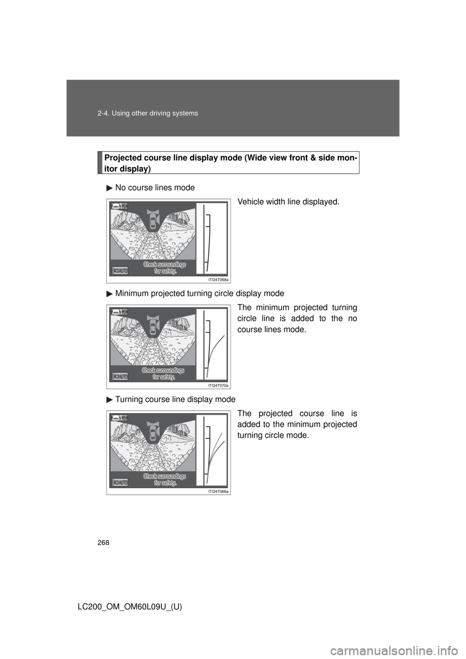
Projected course line display mode (Wide view front & side mon-
itor display)No course lines mode Vehicle width line displayed.
Minimum projected turning circle display mode The minimum projected turning
circle line is added to the no
course lines mode.
Turning course line display mode The projected course line is
added to the minimum projected
turning circle mode.
Page 269 of 724
269
2-4. Using other
driving systems
2
When driving
LC200_OM_OM60L09U_(U)■
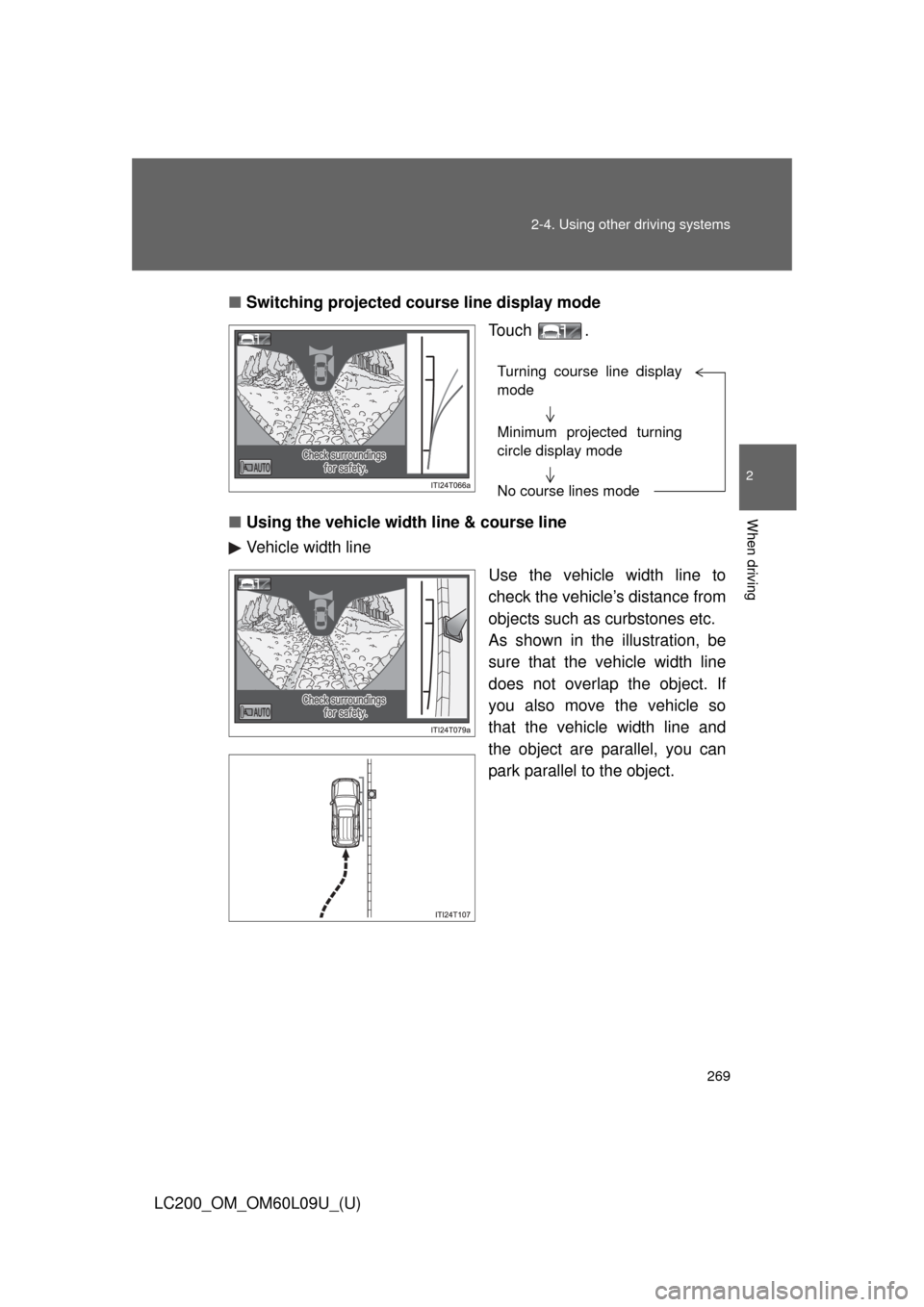
Switching projected cour se line display mode
Touch .
■ Using the vehicle width line & course line
Vehicle width line
Use the vehicle width line to
check the vehicle’s distance from
objects such as curbstones etc.
As shown in the illustration, be
sure that the vehicle width line
does not overlap the object. If
you also move the vehicle so
that the vehicle width line and
the object are parallel, you can
park parallel to the object.
Turning course line display
mode
Minimum projected turning
circle display mode
No course lines mode
Page 270 of 724
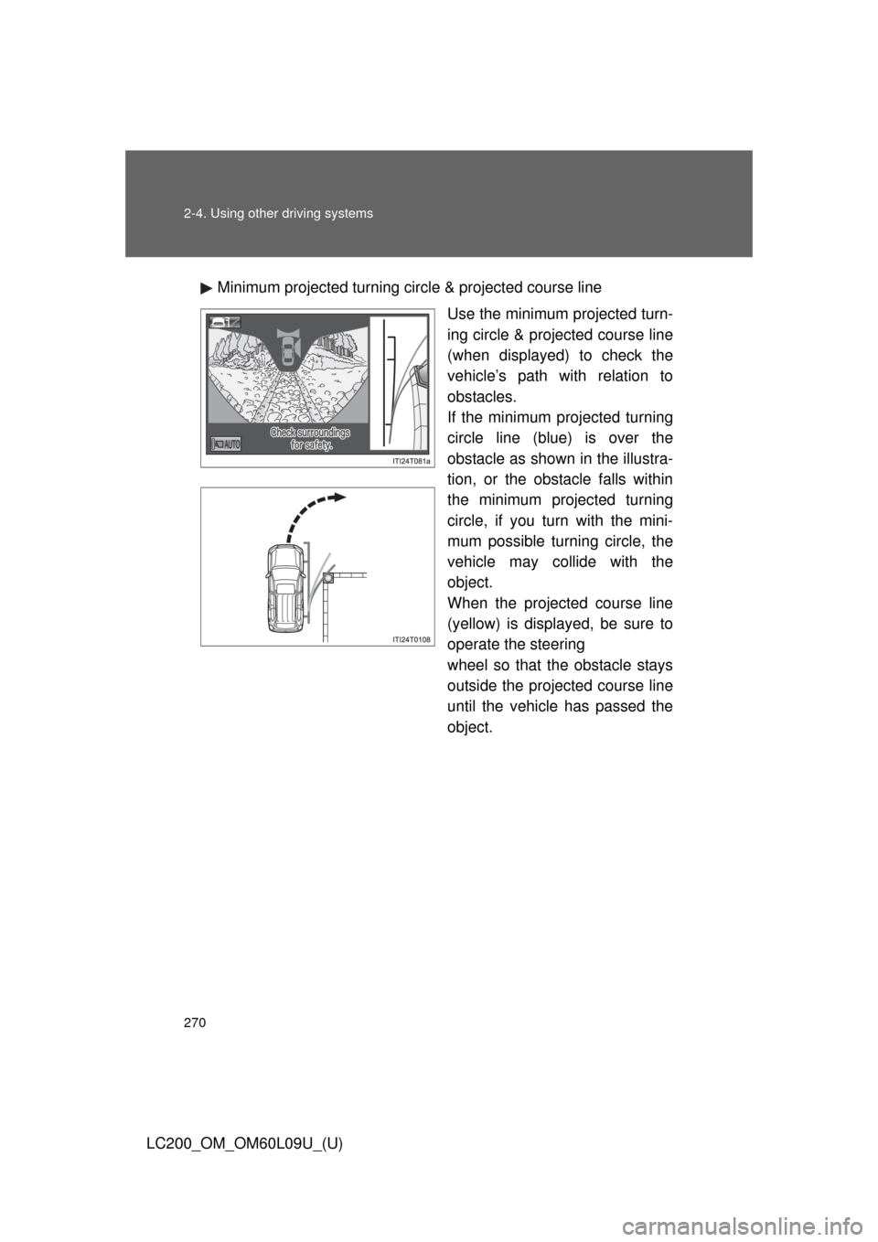
270 2-4. Using other driving systems
LC200_OM_OM60L09U_(U)Minimum projected turning circle & projected course line
Use the minimum projected turn-
ing circle & projected course line
(when displayed) to check the
vehicle’s path with relation to
obstacles.
If the minimum projected turning
circle line (blue) is over the
obstacle as shown in the illustra-
tion, or the obstacle falls within
the minimum projected turning
circle, if you turn with the mini-
mum possible turning circle, the
vehicle may collide with the
object.
When the projected course line
(yellow) is displayed, be sure to
operate the steering
wheel so that the obstacle stays
outside the projected course line
until the vehicle has passed the
object.
Trending: windshield wipers, fuel additives, check engine light, seats, check transmission fluid, cooling, instrument panel
