TOYOTA LAND CRUISER 2016 J200 Owners Manual
Manufacturer: TOYOTA, Model Year: 2016, Model line: LAND CRUISER, Model: TOYOTA LAND CRUISER 2016 J200Pages: 608, PDF Size: 10.91 MB
Page 321 of 608
LC200_OM_OM60M88U_(U)
3214-5. Using the driving support systems
4
Driving
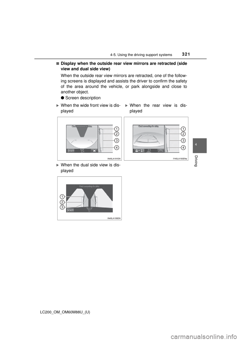
■Display when the outside rear view mirrors are retracted (side
view and dual side view)
When the outside rear view mirrors are retracted, one of the follow-
ing screens is displayed and assist s the driver to confirm the safety
of the area around the vehicle, or park alongside and close to
another object.
● Screen description
When the wide front view is dis-
playedWhen the rear view is dis-
played
When the dual side view is dis-
played
Page 322 of 608

322
LC200_OM_OM60M88U_(U)
4-5. Using the driving support systems
For information about other than the side view and dual side view dis-
play area, refer to the page for the respective screen.
Front distance guide line (red)
Indicates a distance approximately 1.5 ft. (0.5 m) from the front end of the
vehicle.
Front tire contact line (blue)
Indicates the estimated front tire position on the image.
Vehicle width lines (blue)
Indicate the estimated vehicle width including the outside rear view mir-
rors.
Rear tire contact line (blue)
Indicates the estimated rear tire position on the image.
1
2
3
4
Page 323 of 608
LC200_OM_OM60M88U_(U)
3234-5. Using the driving support systems
4
Driving
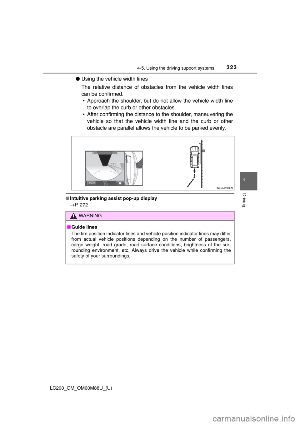
●Using the vehicle width lines
The relative distance of obstacles from the vehicle width lines
can be confirmed.
• Approach the shoulder, but do not allow the vehicle width line
to overlap the curb or other obstacles.
• After confirming the distance to the shoulder, maneuvering the
vehicle so that the vehicle width line and the curb or other
obstacle are parallel allows t he vehicle to be parked evenly.
■Intuitive parking assist pop-up display
P. 272
WARNING
■Guide lines
The tire position indicator lines and vehicle position indicator lines m\
ay differ
from actual vehicle positions depending on the number of passengers,
cargo weight, road grade, road surface conditions, brightness of the sur-
rounding environment, etc. Always drive the vehicle while confirming the
safety of your surroundings.
Page 324 of 608
324
LC200_OM_OM60M88U_(U)
4-5. Using the driving support systems
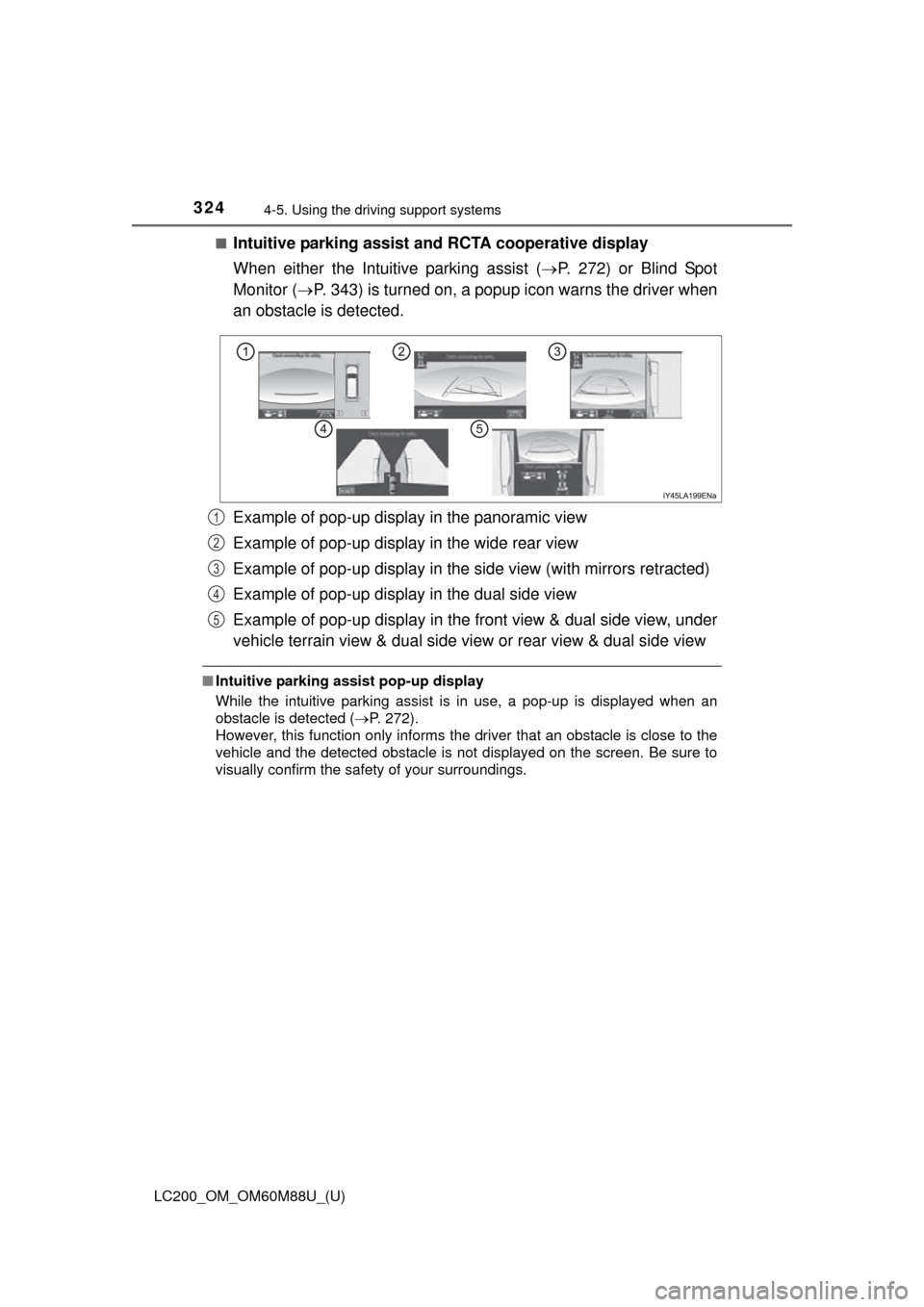
■Intuitive parking assist and RCTA cooperative display
When either the Intuitive parking assist ( P. 272) or Blind Spot
Monitor ( P. 343) is turned on, a popup icon warns the driver when
an obstacle is detected.
Example of pop-up display in the panoramic view
Example of pop-up display in the wide rear view
Example of pop-up display in the side view (with mirrors retracted)
Example of pop-up display in the dual side view
Example of pop-up display in the front view & dual side view, under
vehicle terrain view & dual side view or rear view & dual side view
■ Intuitive parking assist pop-up display
While the intuitive parking assist is in use, a pop-up is displayed when an
obstacle is detected ( P. 272).
However, this function only informs the driver that an obstacle is close to the
vehicle and the detected obstacle is not displayed on the screen. Be sure to
visually confirm the safety of your surroundings.
1
2
3
4
5
Page 325 of 608
LC200_OM_OM60M88U_(U)
3254-5. Using the driving support systems
4
Driving
Observe the following precautions. Failure to do so may result in an
unexpected accident. Also, when driv ing, make sure to directly con-
firm the safety of your surroundings and the area to the rear of the
vehicle.
When using the Multi-terrain Monitor
WARNING
■ Conditions under which the Multi-terrain Monitor should not be used
Do not use the Multi-terrain Monitor in the following situations. The system
may not operate properly, resulting in an unexpected accident.
●When driving on an icy, snow-covered or otherwise slippery road surface
● When using tire chains or a spare tire
● When either front door or the back door is not completely closed
● When driving on an uneven road, such as a hill
● When tires or suspension parts other than those specified are equipped
When the tires are replaced, the position indicated by the guide lines dis-
played on the screen may differ.
■ Guide lines
The tire position indicator lines and vehicle position indicator lines m\
ay differ
from actual vehicle positions depending on the number of passengers,
cargo weight, road grade, road surface conditions, brightness of the sur-
rounding environment, etc. Always drive the vehicle while confirming the
safety of your surroundings.
Page 326 of 608
326
LC200_OM_OM60M88U_(U)
4-5. Using the driving support systems
NOTICE
■Panoramic view
●In the panoramic view, the system combines images taken from the front,
back, left and right side cameras into a single image. There are limits to
the range and content that can be displayed. Understand the characteris-
tics of this system before using.
● Image clarity may decline at the four corners of the panoramic view. How-
ever, this is not a malfunction, as these are the regions along the border of
each camera image where the images are combined.
● Depending on lighting conditions near each of the cameras, bright and
dark patches may appear on the panoramic view.
● The panoramic view display does not extend higher than the installation
position and image capture range of each camera.
● There are blind spots around the vehicl e and there are regions that are not
displayed in the panoramic view.
● Three-dimensional objects displayed in wide front view or rear view may
not be displayed in the panoramic view.
● People and other three-dimensional obstacles may appear differently
when displayed in the panoramic view. (These differences include, among
others, cases in which displayed objects appear to have fallen over, disap-
pear near image processing areas, appear from image processing areas,
or when the actual distance to an object differs from the displayed posi-
tion.)
● The panoramic view will not be properly displayed when either front door
or the back door is open.
● The vehicle icon displayed in the panoramic view is a computer generated
image, and properties such as the color, shape and size will differ from the
actual vehicle. Therefore, nearby three-dimensional objects may appear to
be touching the vehicle, and actual distances to three-dimensional objects
may differ from those displayed.
Page 327 of 608
LC200_OM_OM60M88U_(U)
3274-5. Using the driving support systems
4
Driving
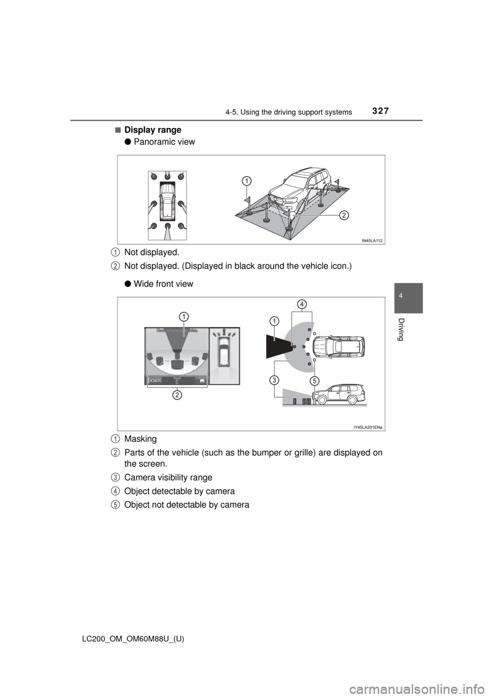
■Display range
●Panoramic view
Not displayed.
Not displayed. (Displayed in black around the vehicle icon.)
● Wide front view
Masking
Parts of the vehicle (such as the bumper or grille) are displayed on
the screen.
Camera visibility range
Object detectable by camera
Object not detectable by camera
1
2
1
2
3
4
5
Page 328 of 608
328
LC200_OM_OM60M88U_(U)
4-5. Using the driving support systems
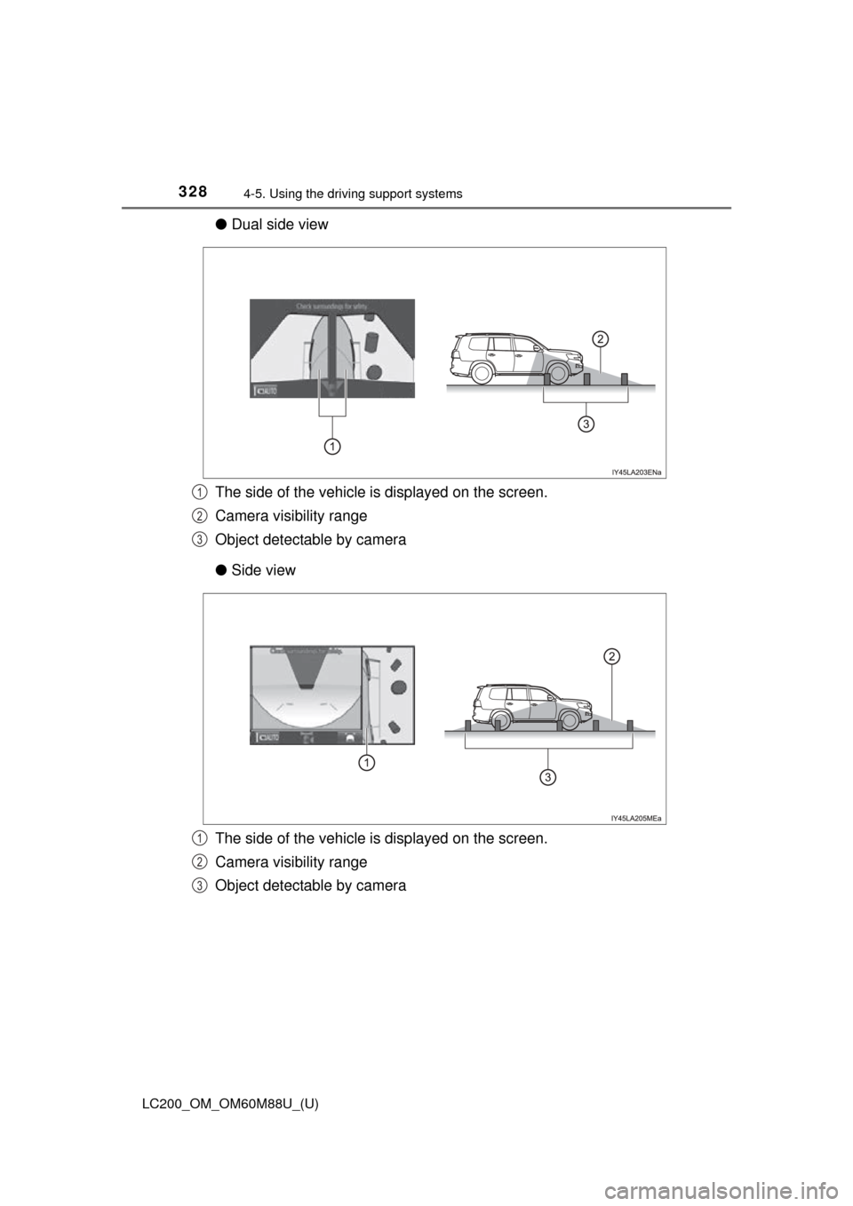
●Dual side view
The side of the vehicle is displayed on the screen.
Camera visibility range
Object detectable by camera
● Side view
The side of the vehicle is displayed on the screen.
Camera visibility range
Object detectable by camera
1
2
3
1
2
3
Page 329 of 608
LC200_OM_OM60M88U_(U)
3294-5. Using the driving support systems
4
Driving
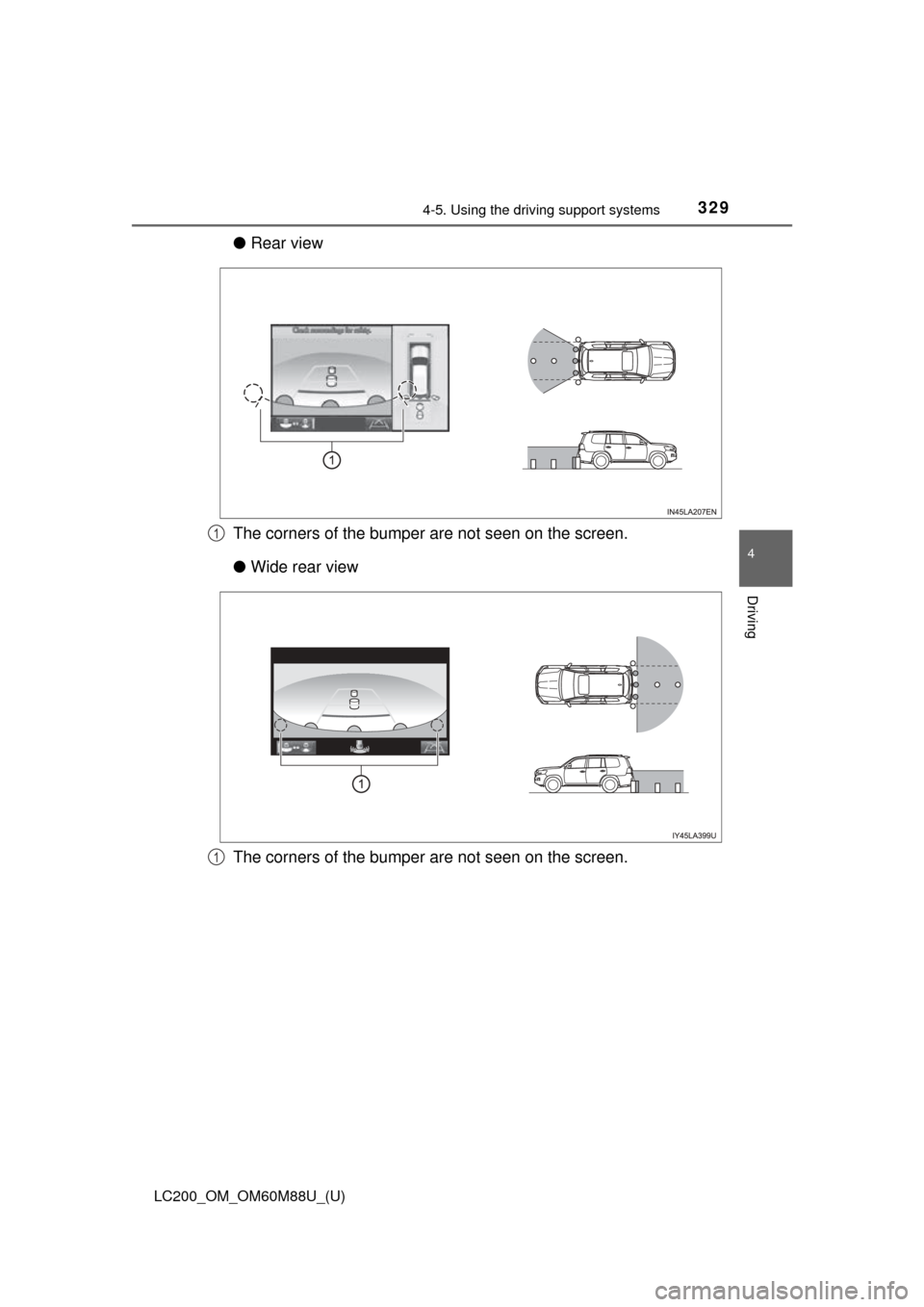
●Rear view
The corners of the bumper are not seen on the screen.
● Wide rear view
The corners of the bumper are not seen on the screen.
1
1
Page 330 of 608
330
LC200_OM_OM60M88U_(U)
4-5. Using the driving support systems
■Panoramic view display range
●In the panoramic view, the system processes and displays images acquired
form the 4 cameras under the assumption that the vehicle is on a flat road
surface. Therefore, the display may appear as follows.
• Three-dimensional objects may appear to have fallen over, and be long
and thin or bigger than they actually are
• Three-dimensional objects at a point higher than the surface of the road
may appear further away than they actually are, or may not appear
• Tall objects may appear to emerge from the image processing seams
● Inconsistencies in the brightness of images from each camera may occur
depending on lighting conditions.
● The displayed image may not be aligned when the tilt or height of the vehi-
cle changed due to the number of passengers, cargo weight or remaining
quantity of gasoline.
● Images and guide lines may not be properly displayed when the doors are
not completely closed.
● The relative distances between the vehicle icon and road surface or an
obstacle displayed in the panoramic view may differ from the actual state.
● If an illuminated license plate is used, it may appear on the screen.
● The black area around the vehicle icon is an area that is not appear in the
camera. Check these areas directly.
■ Wide front view display range
●Certain areas at the front of the vehicle have a different sense of distance,
and are masked in black so that they do not appear on the screen.
● There are limits to the range displayed on the screen. Objects at either cor-
ner of the bumper or directly below the bumper are not displayed.
● The perceived distance in images displayed on the screen differs from the
actual distance.
■ Images displayed on the screen
Cameras of the Multi-terrain Monitor system use special lenses. The distance
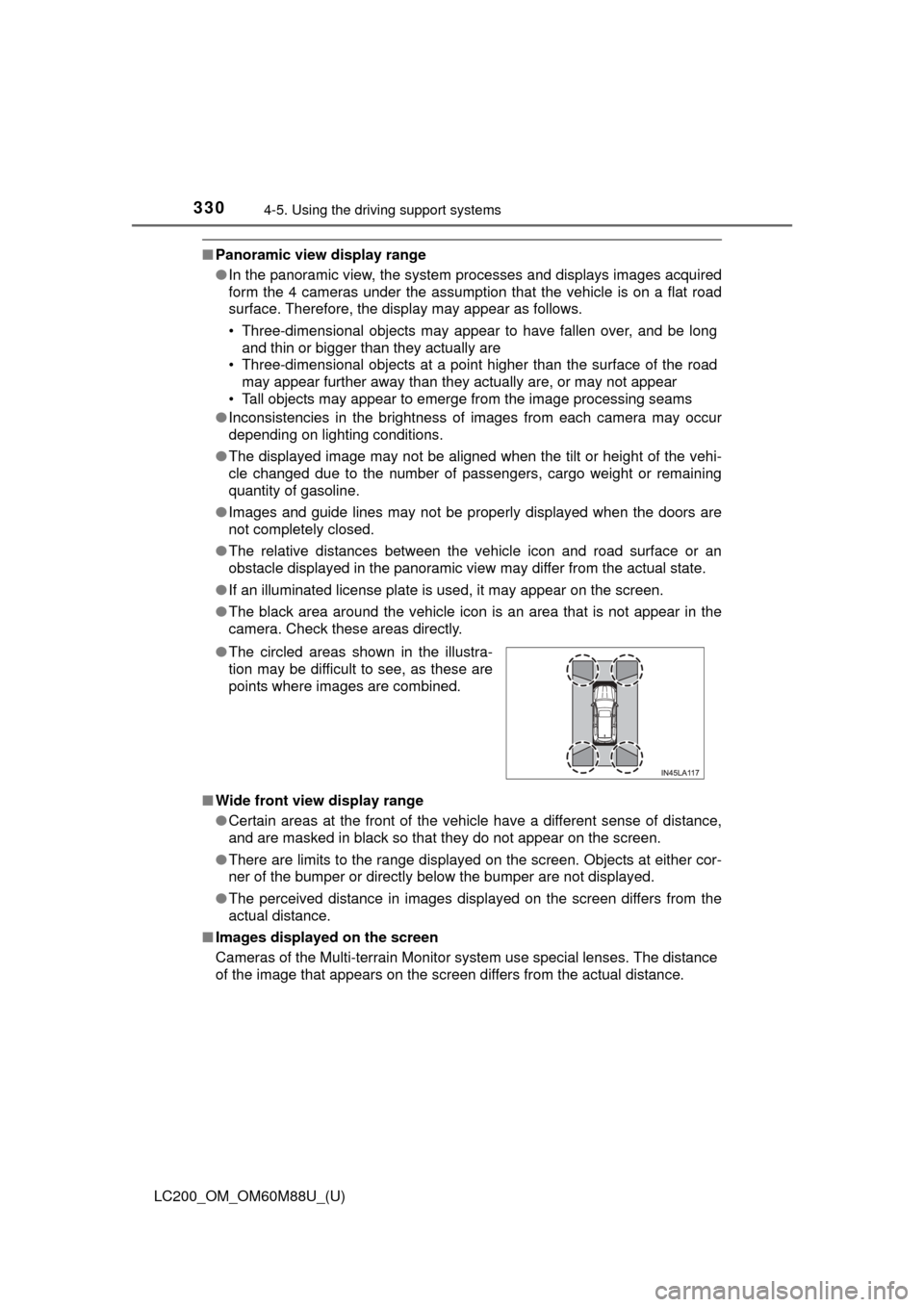
of the image that appears on the screen differs from the actual distance. ●The circled areas shown in the illustra-
tion may be difficult to see, as these are
points where images are combined.