display TOYOTA LAND CRUISER 2017 J200 Owners Manual
[x] Cancel search | Manufacturer: TOYOTA, Model Year: 2017, Model line: LAND CRUISER, Model: TOYOTA LAND CRUISER 2017 J200Pages: 608, PDF Size: 15.88 MB
Page 2 of 608
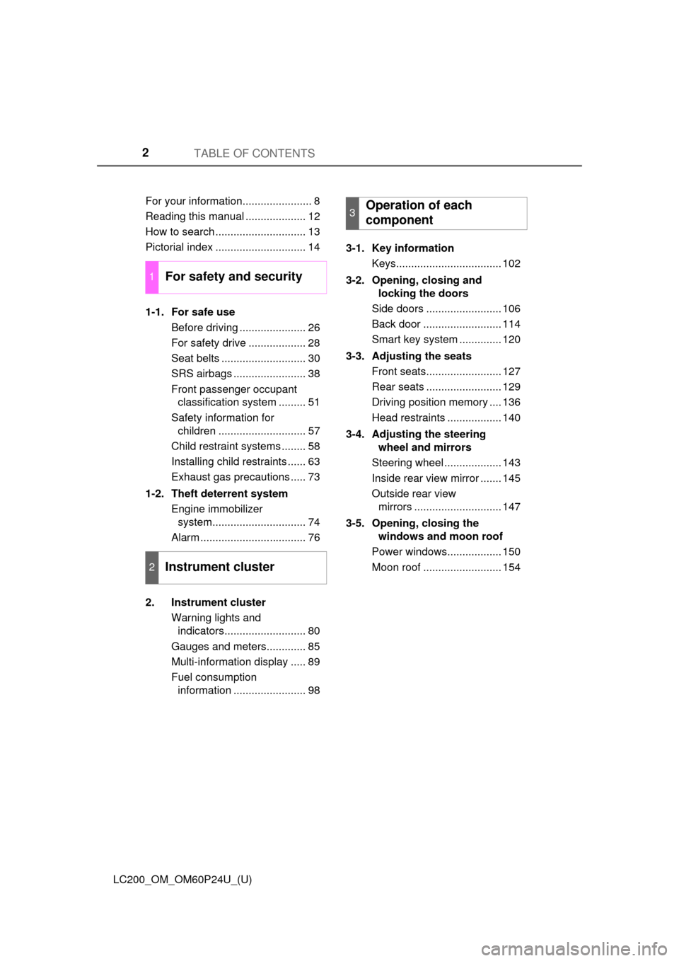
TABLE OF CONTENTS2
LC200_OM_OM60P24U_(U)For your information....................... 8
Reading this manual .................... 12
How to search .............................. 13
Pictorial index .............................. 14
1-1. For safe use
Before driving ...................... 26
For safety drive ................... 28
Seat belts ............................ 30
SRS airbags ........................ 38
Front passenger occupant classification system ......... 51
Safety information for children ............................. 57
Child restraint systems ........ 58
Installing child restraints ...... 63
Exhaust gas precautions ..... 73
1-2. Theft deterrent system Engine immobilizer system............................... 74
Alarm ................................... 76
2. Instrument cluster Warning lights and indicators........................... 80
Gauges and meters............. 85
Multi-information display ..... 89
Fuel consumption information ........................ 98 3-1. Key information
Keys................................... 102
3-2. Opening, closing and locking the doors
Side doors ......................... 106
Back door .......................... 114
Smart key system .............. 120
3-3. Adjusting the seats Front seats......................... 127
Rear seats ......................... 129
Driving position memory .... 136
Head restraints .................. 140
3-4. Adjusting the steering wheel and mirrors
Steering wheel ................... 143
Inside rear view mirror ....... 145
Outside rear view mirrors ............................. 147
3-5. Opening, closing the windows and moon roof
Power windows.................. 150
Moon roof .......................... 154
1For safety and security
2Instrument cluster
3Operation of each
component
Page 4 of 608

TABLE OF CONTENTS4
LC200_OM_OM60P24U_(U)5-1. Using the air conditioning
system and defogger
Front automatic air conditioning system ........ 374
Rear air conditioning system............................. 385
Heated steering wheel/ seat heaters/
seat ventilators ................ 389
5-2. Using the interior lights Interior lights list ................ 393• Interior lights ................. 394
• Personal lights .............. 395
5-3. Using the storage features List of storage features...... 396• Glove box...................... 397
• Console box .................. 398
• Overhead console ......... 399
• Cup holders .................. 400
• Bottle holders ................ 402
• Card holders ................. 403
• Auxiliary boxes .............. 403
Luggage compartment features ........................... 404 5-4. Using the other interior
features
Other interior features........ 406 • Cool box ........................ 406
• Sun visors ..................... 408
• Vanity mirror .................. 408
• Clock ............................. 409
• Outside temperature
display ........................... 409
• Power outlets ................ 410
• Wireless charger ........... 412
• Armrest.......................... 420
• Coat hooks .................... 420
• Assist grips .................... 421
Garage door opener .......... 422
Safety Connect .................. 427
5Interior features
Page 5 of 608
5
1
8 7
6
5
4
3
2
LC200_OM_OM60P24U_(U)
9
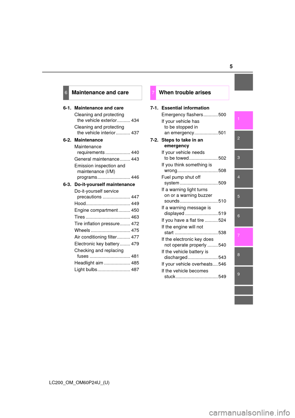
6-1. Maintenance and careCleaning and protecting the vehicle exterior .......... 434
Cleaning and protecting the vehicle interior ........... 437
6-2. Maintenance Maintenance requirements ................... 440
General maintenance ........ 443
Emission inspection and maintenance (I/M)
programs ......................... 446
6-3. Do-it-yourself maintenance Do-it-yourself service precautions ..................... 447
Hood.................................. 449
Engine compartment ......... 450
Tires .................................. 463
Tire inflation pressure........ 472
Wheels .............................. 475
Air conditioning filter .......... 477
Electronic key battery ........ 479
Checking and replacing fuses ............................... 481
Headlight aim .................... 485
Light bulbs ......................... 487 7-1. Essential information
Emergency flashers ........... 500
If your vehicle has to be stopped in
an emergency.................. 501
7-2. Steps to take in an emergency
If your vehicle needs to be towed ...................... 502
If you think something is wrong............................... 508
Fuel pump shut off system ............................. 509
If a warning light turns on or a warning buzzer
sounds ............................. 510
If a warning message is displayed ......................... 519
If you have a flat tire .......... 524
If the engine will not start ................................. 538
If the electronic key does not operate properly ........ 540
If the vehicle battery is discharged ....................... 543
If your vehicle overheats.... 546
If the vehicle becomes stuck ................................ 549
6Maintenance and care7When trouble arises
Page 17 of 608
17Pictorial index
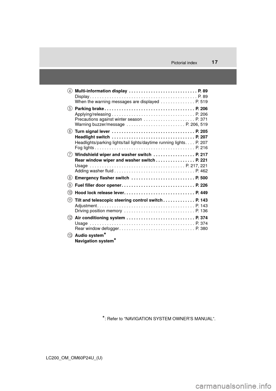
LC200_OM_OM60P24U_(U)Multi-information display . . . . . . . . . . . . . . . . . . . . . . . . . . . . P. 89
Display . . . . . . . . . . . . . . . . . . . . . . . . . . . . . . . . . . . . . . . . . . . . P. 89
When the warning messages are displayed . . . . . . . . . . . . . . P. 519
Parking brake . . . . . . . . . . . . . . . . . . . . . . . . . . . . . . . . . . . . . P. 206
Applying/releasing . . . . . . . . . . . . . . . . . . . . . . . . . . . . . . . . . . P. 206
Precautions against winter season . . . . . . . . . . . . . . . . . . . . . P. 371
Warning buzzer/message . . . . . . . . . . . . . . . . . . . . . . . . P. 206, 519
Turn signal lever . . . . . . . . . . . . . . . . . . . . . . . . . . . . . . . . . . P. 205
Headlight switch . . . . . . . . . . . . . . . . . . . . . . . . . . . . . . . . . . P. 207
Headlights/parking lights/tail lights/daytime running lights . . . . P. 207
Fog lights . . . . . . . . . . . . . . . . . . . . . . . . . . . . . . . . . . . . . . . . . P. 216
Windshield wiper and washer switch . . . . . . . . . . . . . . . . . P. 217
Rear window wiper and washer switch . . . . . . . . . . . . . . . . P. 221
Usage . . . . . . . . . . . . . . . . . . . . . . . . . . . . . . . . . . . . . . . P. 217, 221
Adding washer fluid . . . . . . . . . . . . . . . . . . . . . . . . . . . . . . . . . P. 462
Emergency flasher switch . . . . . . . . . . . . . . . . . . . . . . . . . . P. 500
Fuel filler door opener . . . . . . . . . . . . . . . . . . . . . . . . . . . . . . P. 226
Hood lock release lever. . . . . . . . . . . . . . . . . . . . . . . . . . . . . P. 449
Tilt and telescopic steering control switch . . . . . . . . . . . . . P. 143
Adjustment . . . . . . . . . . . . . . . . . . . . . . . . . . . . . . . . . . . . . . . . P. 143
Driving position memory . . . . . . . . . . . . . . . . . . . . . . . . . . . . . P. 136
Air conditioning system . . . . . . . . . . . . . . . . . . . . . . . . . . . . P. 374
Usage . . . . . . . . . . . . . . . . . . . . . . . . . . . . . . . . . . . . . . . . . . . P. 374
Rear window defogger . . . . . . . . . . . . . . . . . . . . . . . . . . . . . . . P. 380
Audio system
*
Navigation system*
*
: Refer to “NAVIGATION SYSTEM OWNER’S MANUAL”.
4
5
6
7
8
9
10
11
12
13
Page 63 of 608
631-1. For safe use
LC200_OM_OM60P24U_(U)
1
For safety and security
Installing child restraints
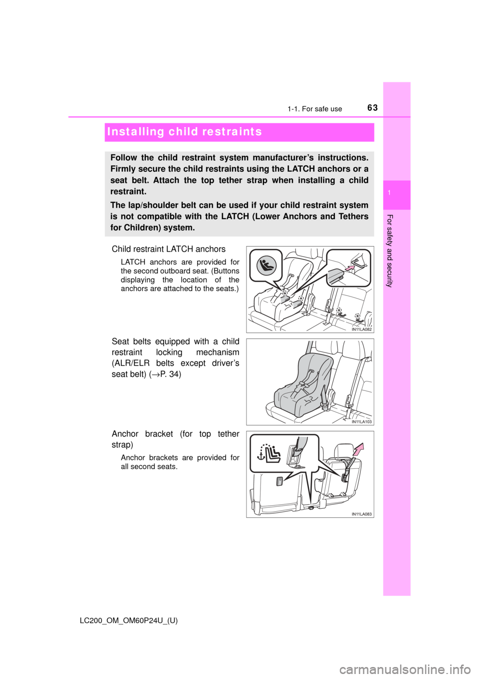
Child restraint LATCH anchors
LATCH anchors are provided for
the second outboard seat. (Buttons
displaying the location of the
anchors are attached to the seats.)
Seat belts equipped with a child
restraint locking mechanism
(ALR/ELR belts except driver’s
seat belt) (→P. 34)
Anchor bracket (for top tether
strap)
Anchor brackets are provided for
all second seats.
Follow the child restraint system manufacturer’s instructions.
Firmly secure the child restraints using the LATCH anchors or a
seat belt. Attach the top tether strap when installing a child
restraint.
The lap/shoulder belt can be used if your child restraint system
is not compatible with the LATCH (Lower Anchors and Tethers
for Children) system.
Page 79 of 608

79
LC200_OM_OM60P24U_(U)
Instrument cluster2
2. Instrument clusterWarning lights and indicators .......................... 80
Gauges and meters ............ 85
Multi-information display ..... 89
Fuel consumption information ........................ 98
Page 80 of 608
80
LC200_OM_OM60P24U_(U)
2. Instrument cluster
Warning lights and indicators
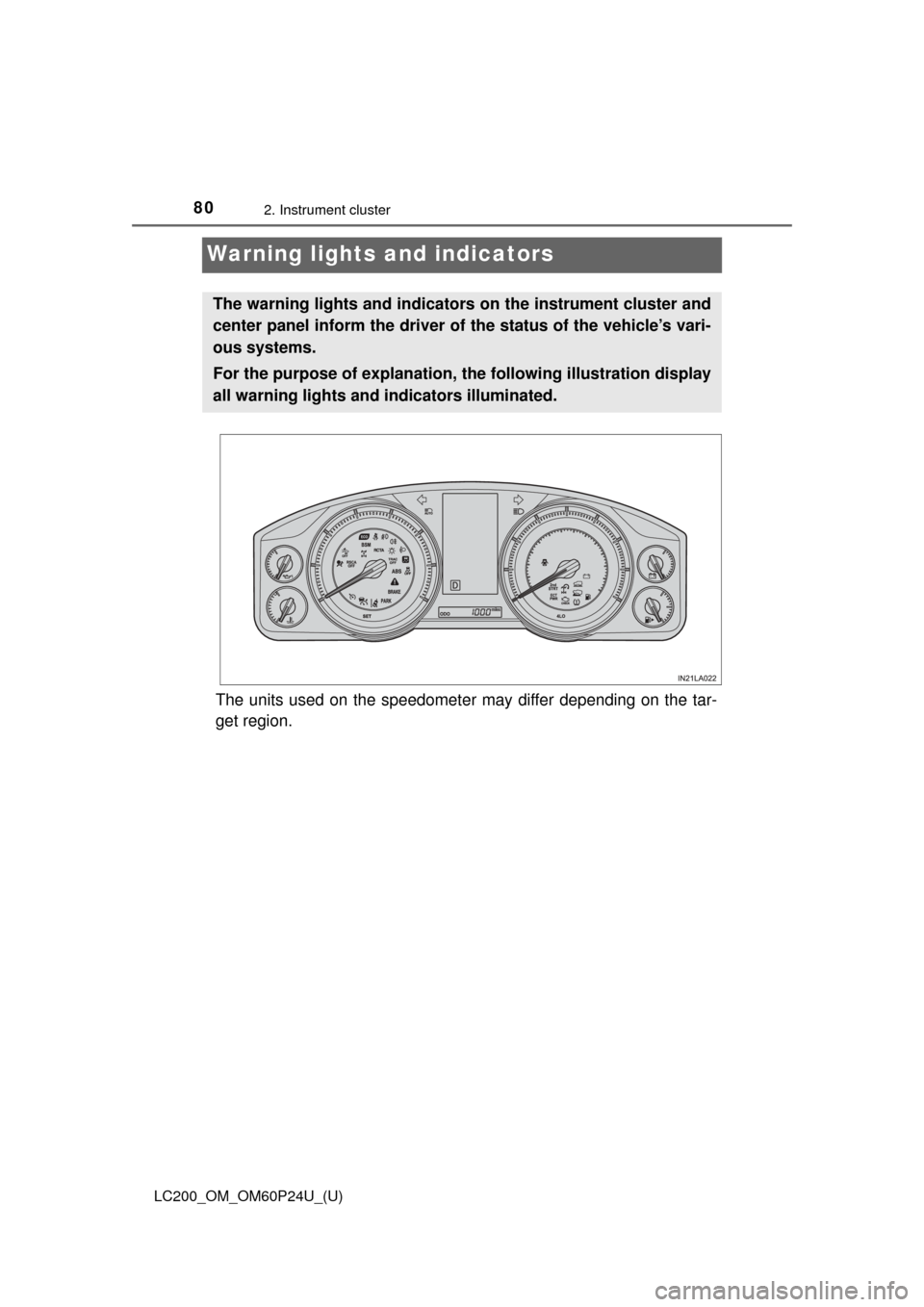
The units used on the speedometer may differ depending on the tar-
get region.
The warning lights and indicators on the instrument cluster and
center panel inform the driver of the status of the vehicle’s vari-
ous systems.
For the purpose of explanation, th e following illustration display
all warning lights and indicators illuminated.
Page 85 of 608
85
LC200_OM_OM60P24U_(U)
2. Instrument cluster
2
Instrument cluster
Gauges and meters
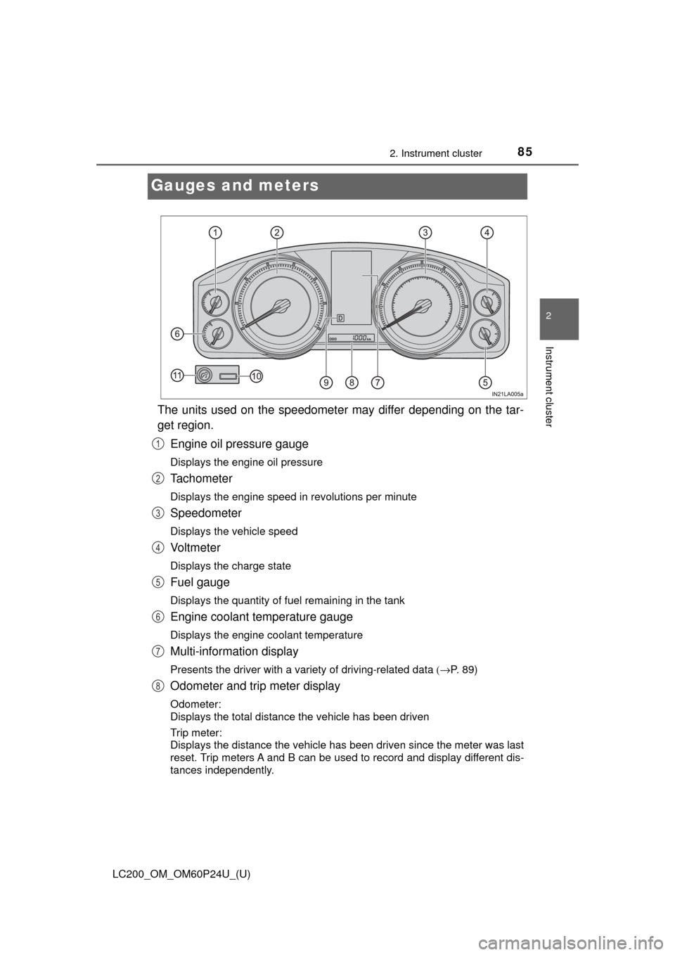
The units used on the speedometer may differ depending on the tar-
get region.Engine oil pressure gauge
Displays the engine oil pressure
Tachometer
Displays the engine speed in revolutions per minute
Speedometer
Displays the vehicle speed
Vo l t m e t e r
Displays the charge state
Fuel gauge
Displays the quantity of fuel remaining in the tank
Engine coolant temperature gauge
Displays the engine coolant temperature
Multi-information display
Presents the driver with a variety of driving-related data (→P. 89)
Odometer and trip meter display
Odometer:
Displays the total distance the vehicle has been driven
Trip meter:
Displays the distance the vehicle has been driven since the meter was last
reset. Trip meters A and B can be used to record and display different dis-
tances independently.
1
2
3
4
5
6
7
8
Page 86 of 608
86
LC200_OM_OM60P24U_(U)
2. Instrument cluster
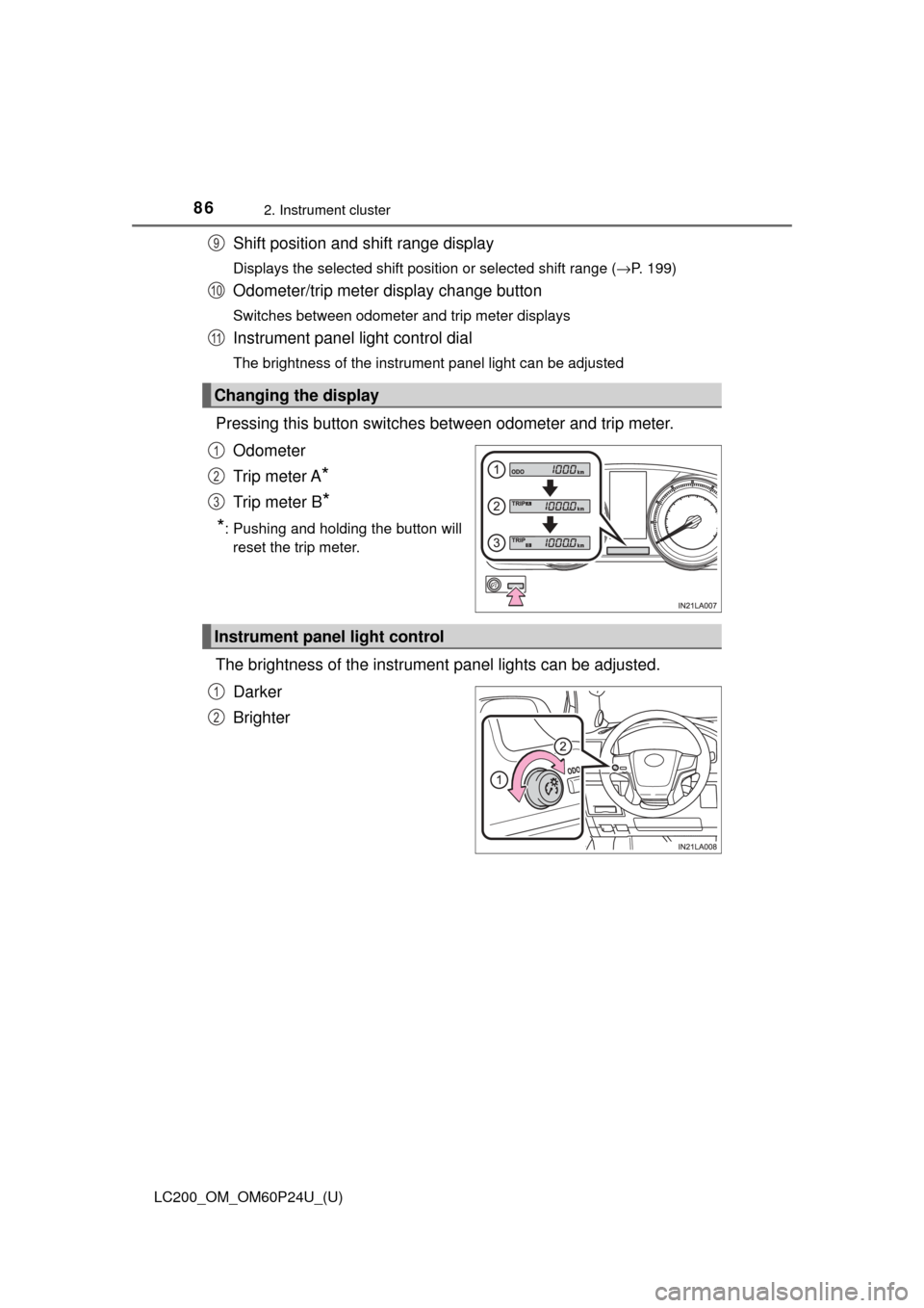
Shift position and shift range display
Displays the selected shift position or selected shift range (→P. 199)
Odometer/trip meter display change button
Switches between odometer and trip meter displays
Instrument panel light control dial
The brightness of the instrument panel light can be adjusted
Pressing this button switches between odometer and trip meter.
Odometer
Trip meter A
*
Trip meter B*
*
: Pushing and holding the button will reset the trip meter.
The brightness of the instrument panel lights can be adjusted.
Darker
Brighter
Changing the display
9
10
11
1
2
3
Instrument panel light control
1
2
Page 87 of 608
LC200_OM_OM60P24U_(U)
872. Instrument cluster
2
Instrument cluster
■The meters and display illuminate when
The engine switch is in IGNITION ON mode.
■ The brightness of the instrument panel lights
When the tail lights are turned on, the meter’s brightness will be reduced
slightly unless the meter brightness level adjustment is set to the brightest
setting.
If the tail lights are turned on when the surroundings are dark, the meter’s
brightness will reduce slightly. Howe ver, when the surroundings are bright,
such as during the daytime, the meter’s brightness will not be reduced even if
the tail lights are turned on.
■ Customization
The meter display can be customized on the multi-information display.
(Customizable features: →P. 574)
WARNING
■ The information display at low temperatures
Allow the interior of the vehicle to warm up before using the liquid crystal
information display. At extremely low temperatures, the information display
monitor may respond slowly, and display changes may be delayed.
For example, there is a lag between the driver’s shifting and the new gear
number appearing on the display. This l ag could cause the driver to down-
shift again, causing rapid and excessive engine braking and possibly an
accident resulting in death or injury.