instrument panel TOYOTA MATRIX 2010 E140 / 2.G Owners Manual
[x] Cancel search | Manufacturer: TOYOTA, Model Year: 2010, Model line: MATRIX, Model: TOYOTA MATRIX 2010 E140 / 2.GPages: 448, PDF Size: 9.74 MB
Page 13 of 448
13
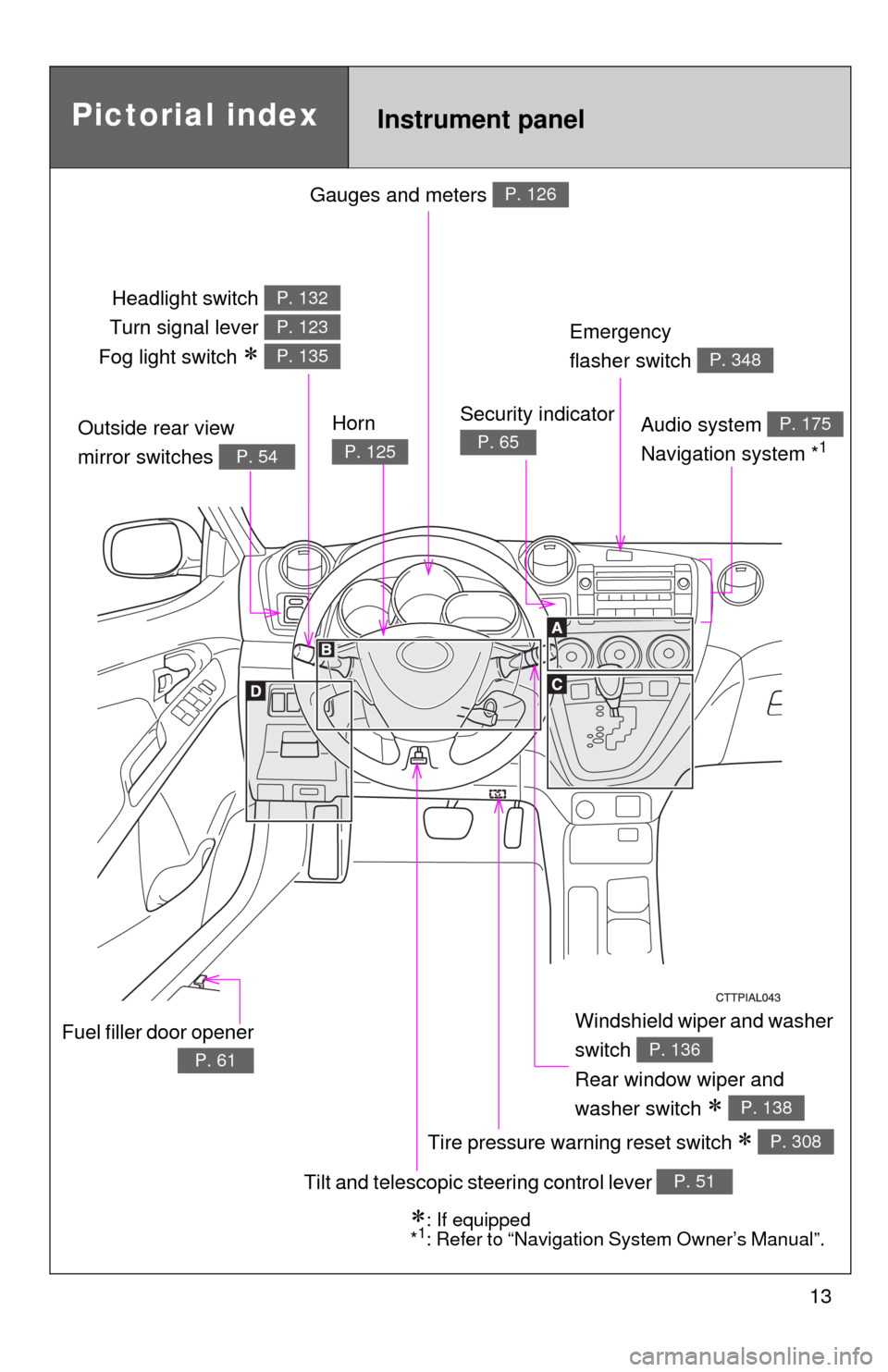
Gauges and meters P. 126
Tilt and telescopic steering control lever P. 51
Pictorial index
Headlight switch
Turn signal lever
Fog light switch
P. 132
P. 123
P. 135
Instrument panel
Audio system
Navigation system *1
P. 175
Windshield wiper and washer
switch
Rear window wiper and
washer switch
P. 136
P. 138
Security indicator
P. 65Outside rear view
mirror switches
P. 54
Tire pressure warning reset switch P. 308
Fuel filler door opener
P. 61
: If equipped
*1: Refer to “Navigation System Owner’s Manual”.
Emergency
flasher switch
P. 348
Horn
P. 125
Page 14 of 448
14
A
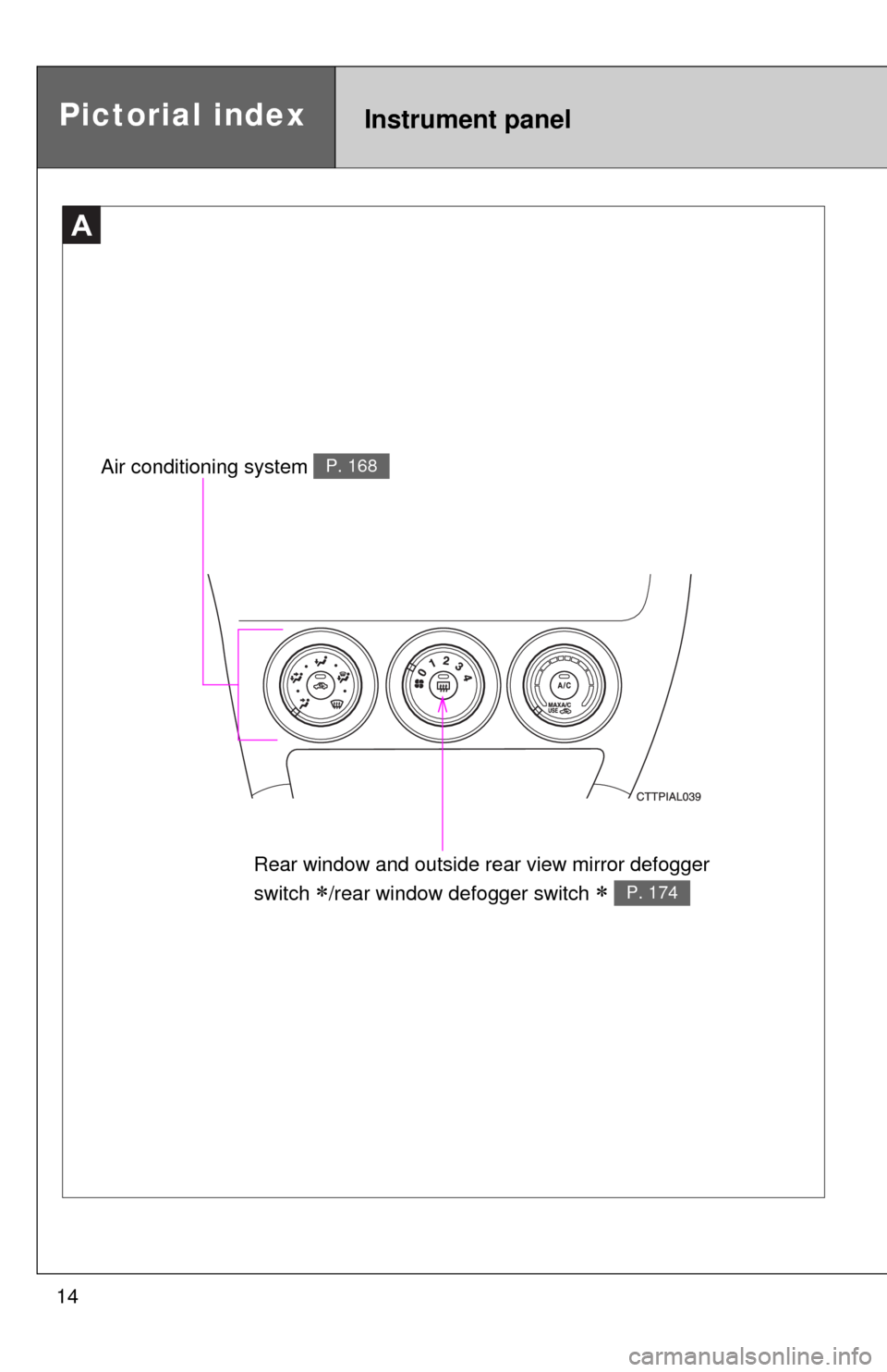
Rear window and outside rear view mirror defogger
switch
/rear window defogger switch P. 174
Air conditioning system P. 168
Pictorial indexInstrument panel
Page 16 of 448
16
C
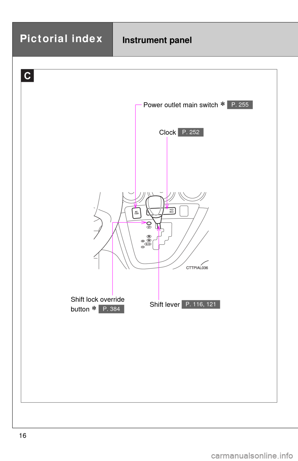
Power outlet main switch P. 255
Clock P. 252
Shift lever P. 116, 121Shift lock override
button
P. 384
Instrument panelPictorial index
Page 77 of 448

77 1-7. Safety information
1
Before driving
CAUTION
■SRS airbag precautions
Observe the following precautions regarding the airbags.
Failure to do so may cause death or serious injury.
●The driver and all passengers in the vehicle must wear their seat belts
properly.
The SRS airbags are supplemental devices to be used with the seat belts.
●The SRS driver airbag deploys with considerable force, and can cause
death or serious injury especially if the driver is very close to the airbag.
The National Highway Traffic Safety Administration (“NHTSA”) advises:
Since the risk zone for the driver’s airbag is the first 2 - 3 in. (50 - 75 mm)
of inflation, placing yourself 10 in. (250 mm) from your driver airbag pro-
vides you with a clear margin of safety. This distance is measured from the
center of the steering wheel to your breastbone. If you sit less than 10 in.
(250 mm) away now, you can change your driving position in several
ways:
• Move your seat to the rear as far as you can while still reaching the
pedals comfortably.
• Slightly recline the back of the seat.
Although vehicle designs vary, many drivers can achieve the 10 in.
(250 mm) distance, even with the driver seat all the way forward, sim-
ply by reclining the back of the seat somewhat. If reclining the back of
your seat makes it hard to see the road, raise yourself by using a firm,
non-slippery cushion, or raise the seat if your vehicle has that feature.
• If your steering wheel is adjustable, tilt it downward. This points the air-
bag toward your chest instead of your head and neck.
The seat should be adjusted as recommended by NHTSA above, while
still maintaining control of the foot pedals, steering wheel, and your view of
the instrument panel controls.
Page 81 of 448

81 1-7. Safety information
1
Before driving
CAUTION
■SRS airbag precautions
●If breathing becomes difficult after the SRS airbag has deployed, open a
door or window to allow fresh air in, or leave the vehicle if it is safe to do
so. Wash off any residue as soon as possible to prevent skin irritation.
●If the areas where the SRS airbags are stored, such as the steering wheel
pad and front and rear pillar garnishes, are damaged or cracked, have
them replaced by your Toyota dealer.
■Modification and disposal of SRS airbag system components
Do not dispose of your vehicle or perform any of the following modifications
without consulting your Toyota dealer.
The SRS airbags may malfunction or deploy (inflate) accidentally, causing
death or serious injury.
●Installation, removal, disassembly and repair of the SRS airbags.
●Repairs, modifications, removal or replacement of the steering wheel,
instrument panel, dashboard, seats or seat upholstery, front, side and rear
pillars or roof side rail.
●Repairs or modifications of the front fender, front bumper, or side of the
occupant compartment.
●Installation of snow plows, winches, etc. to the front grille (bull bars, kan-
garoo bar etc.).
●Modifications to the vehicle's suspension system.
●Installation of electronic devices such as mobile two-way radios or CD
players.
●Modifications to your vehicle for a person with a physical disability.
Page 126 of 448
126
2-2. Instrument cluster
Gauges and meters
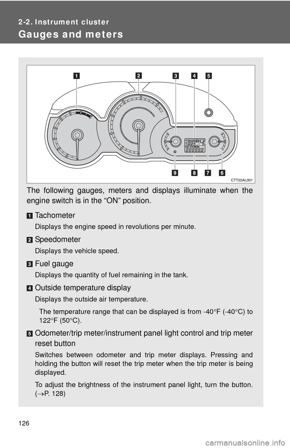
The following gauges, meters and displays illuminate when the
engine switch is in the “ON” position.
Tachometer
Displays the engine speed in revolutions per minute.
Speedometer
Displays the vehicle speed.
Fuel gauge
Displays the quantity of fuel remaining in the tank.
Outside temperature display
Displays the outside air temperature.
The temperature range that can be displayed is from -40F (-40C) to
122F (50C).
Odometer/trip meter/instrument panel light control and trip meter
reset button
Switches between odometer and trip meter displays. Pressing and
holding the button will reset the trip meter when the trip meter is being
displayed.
To adjust the brightness of the instrument panel light, turn the button.
(P. 128)
Page 128 of 448
128 2-2. Instrument cluster
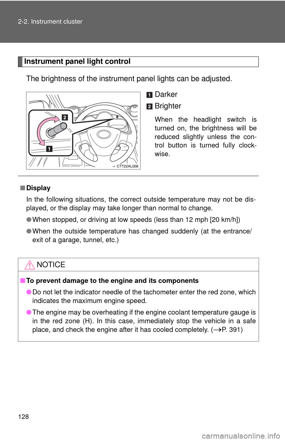
Instrument panel light control
The brightness of the instrument panel lights can be adjusted.
Darker
Brighter
When the headlight switch is
turned on, the brightness will be
reduced slightly unless the con-
trol button is turned fully clock-
wise.
■Display
In the following situations, the correct outside temperature may not be dis-
played, or the display may take longer than normal to change.
●When stopped, or driving at low speeds (less than 12 mph [20 km/h])
●When the outside temperature has changed suddenly (at the entrance/
exit of a garage, tunnel, etc.)
NOTICE
■To prevent damage to the engine and its components
●Do not let the indicator needle of the tachometer enter the red zone, which
indicates the maximum engine speed.
●The engine may be overheating if the engine coolant temperature gauge is
in the red zone (H). In this case, immediately stop the vehicle in a safe
place, and check the engine after it has cooled completely. (
P. 391)
Page 129 of 448
129
2-2. Instrument cluster
2
When driving
Indicators and warning lights
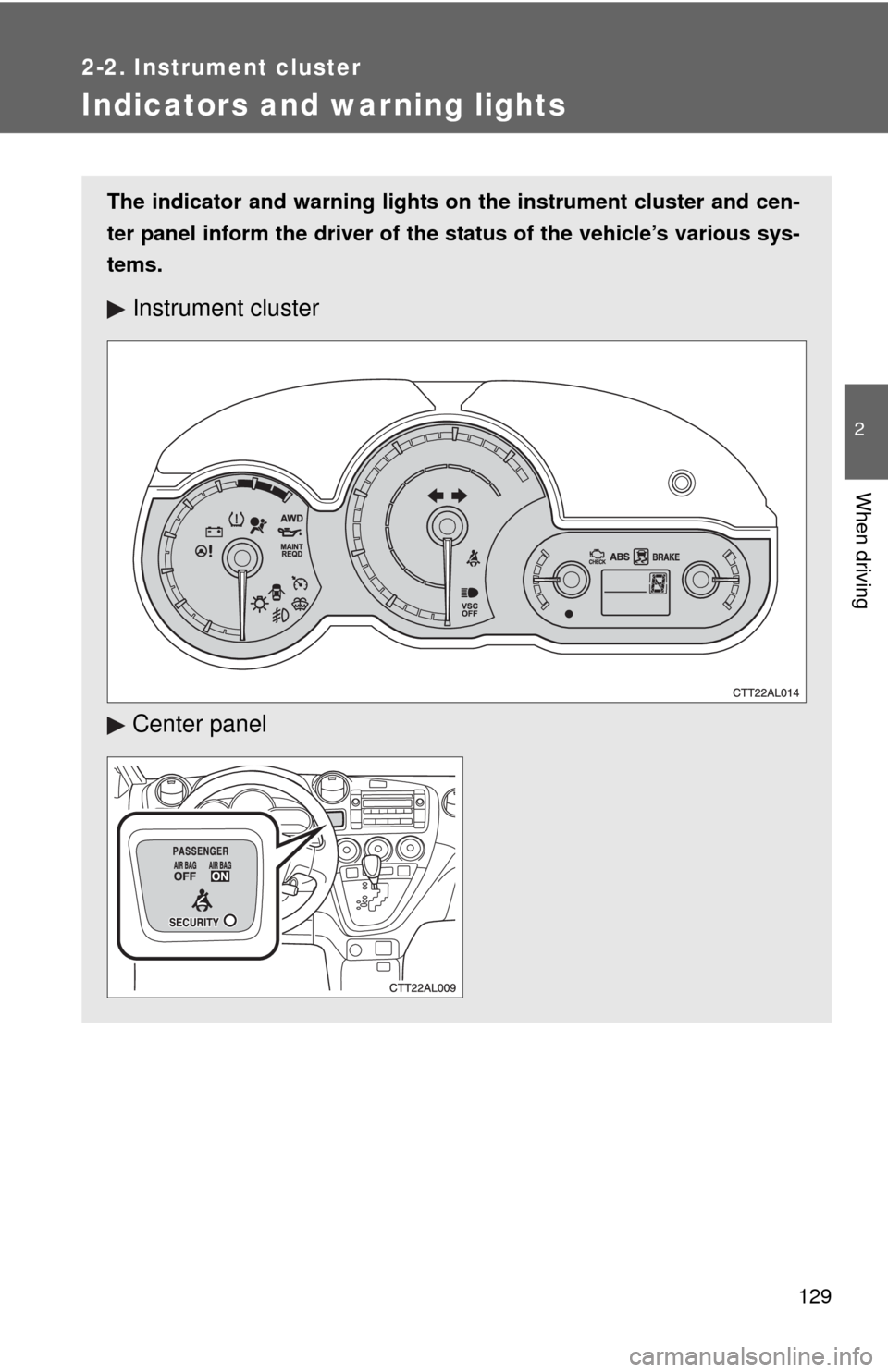
The indicator and warning lights on the instrument cluster and cen-
ter panel inform the driver of the status of the vehicle’s various sys-
tems.
Instrument cluster
Center panel
Page 132 of 448
132
2-3. Operating the lights and wipers
Headlight switch
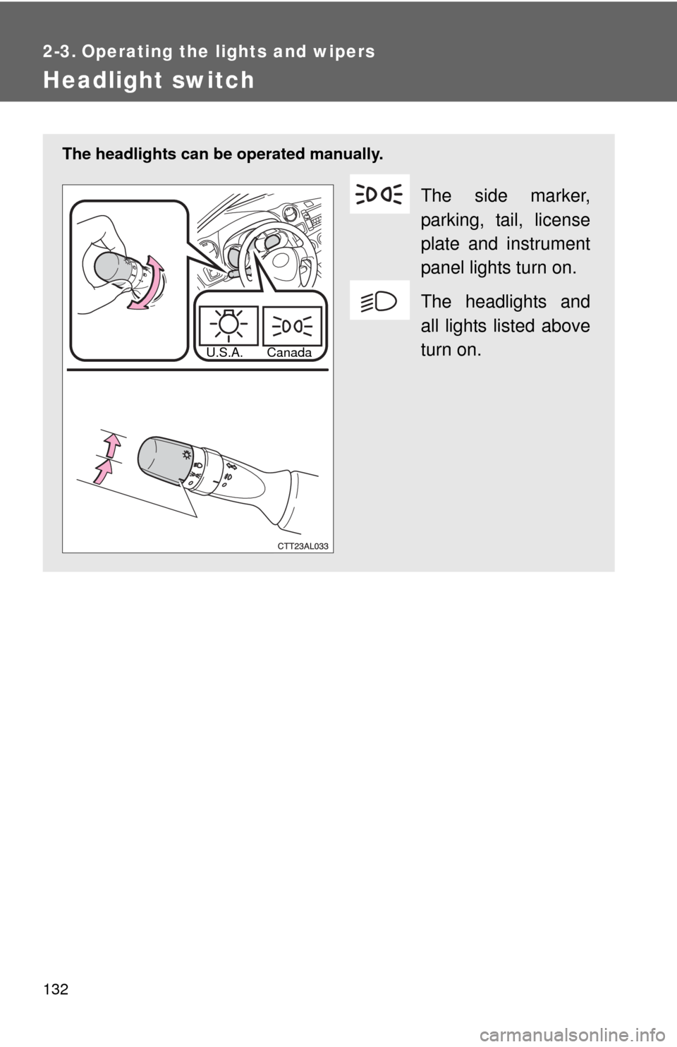
The headlights can be operated manually.
The side marker,
parking, tail, license
plate and instrument
panel lights turn on.
The headlights and
all lights listed above
turn on.
U.S.A. Canada
Page 133 of 448
133 2-3. Operating the lights and wipers
2
When driving
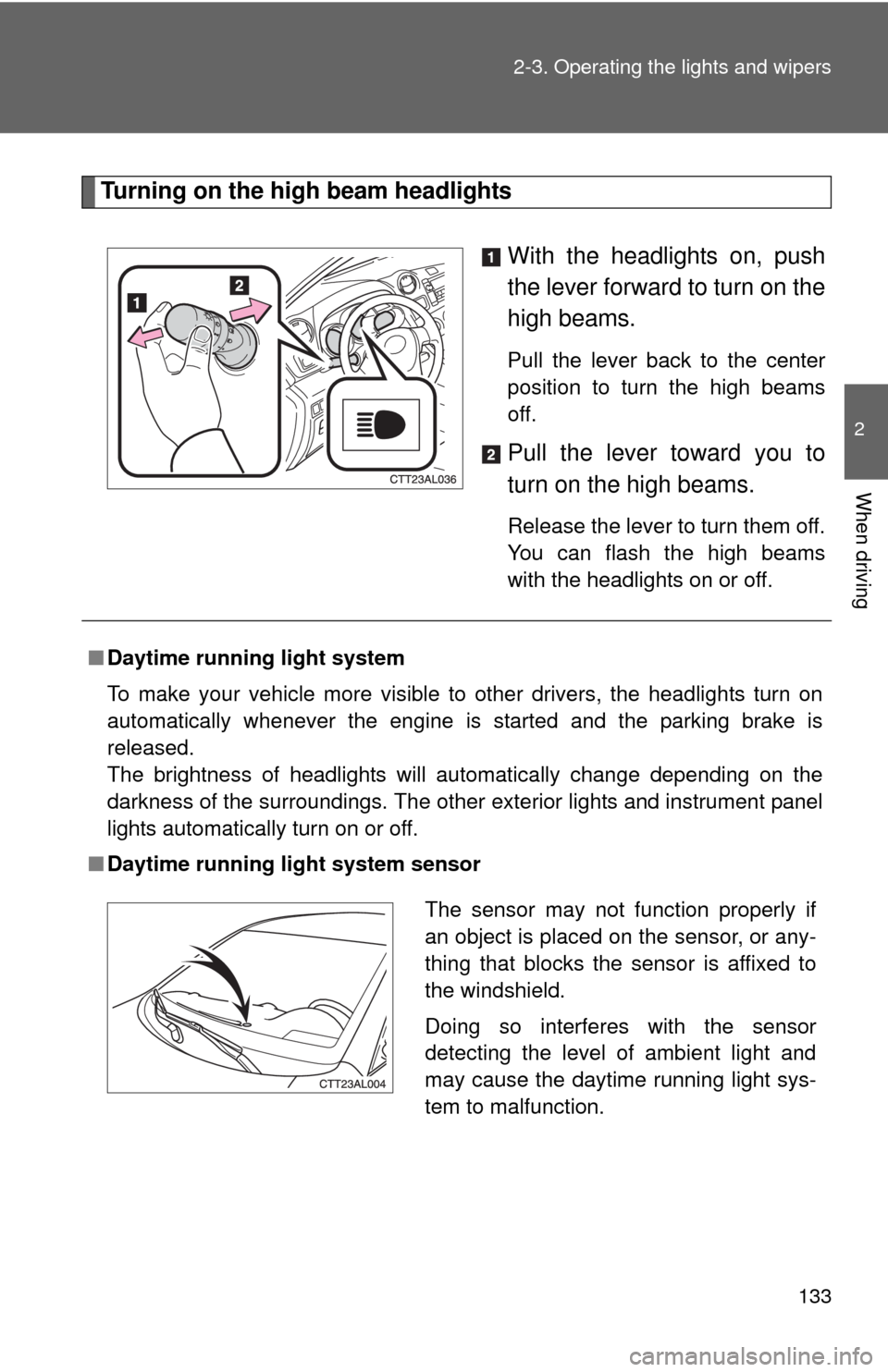
Turning on the high beam headlights
With the headlights on, push
the lever forward to turn on the
high beams.
Pull the lever back to the center
position to turn the high beams
off.
Pull the lever toward you to
turn on the high beams.
Release the lever to turn them off.
You can flash the high beams
with the headlights on or off.
■Daytime running light system
To make your vehicle more visible to other drivers, the headlights turn on
automatically whenever the engine is started and the parking brake is
released.
The brightness of headlights will automatically change depending on the
darkness of the surroundings. The other exterior lights and instrument panel
lights automatically turn on or off.
■Daytime running light system sensor
The sensor may not function properly if
an object is placed on the sensor, or any-
thing that blocks the sensor is affixed to
the windshield.
Doing so interferes with the sensor
detecting the level of ambient light and
may cause the daytime running light sys-
tem to malfunction.