air conditioning TOYOTA MIRAI 2018 Owners Manual (in English)
[x] Cancel search | Manufacturer: TOYOTA, Model Year: 2018, Model line: MIRAI, Model: TOYOTA MIRAI 2018Pages: 464, PDF Size: 8.61 MB
Page 4 of 464

TABLE OF CONTENTS4
MIRAI_OM_USA_OM62025U6-1. Using the air conditioning
system and defogger
Automatic air conditioning system............................. 256
Heated steering wheel/ seat heaters .................... 265
6-2. Using the interior lights Interior lights list ................ 267• Interior lights ................. 268
• Personal lights .............. 268
6-3. Using the storage features List of storage features...... 270• Glove box...................... 271
• Console box .................. 271
• Cup holders .................. 272
• Bottle holders ................ 274
• Auxiliary box ................. 274
Trunk features ................... 275
6-4. Other interior features Other interior features ....... 277• Sun visors ..................... 277
• Vanity mirrors................ 277
• Clock ............................. 278
• Armrest ......................... 279
• Coat hooks.................... 279
• Assist grips ................... 280
• Power outlet .................. 281
• USB charging ports....... 282
• Wireless charger ........... 284
Garage door opener .......... 292
Safety Connect.................. 299 7-1. Maintenance and care
Cleaning and protecting the vehicle exterior .......... 306
Cleaning and protecting the vehicle interior ........... 310
7-2. Maintenance Maintenance requirements ................... 313
General maintenance ........ 315
7-3. Do-it-yourself maintenance
Do-it-yourself service precautions ...................... 318
Hood .................................. 320
Positioning a floor jack....... 321
Motor compartment ........... 323
12-volt battery .................... 328
Tires................................... 332
Replacing the tire............... 339
Tire inflation pressure ........ 346
Wheels............................... 349
Air conditioning filter .......... 351
Electronic key battery ........ 353
Checking and replacing fuses ................................ 355
Light bulbs ......................... 358
6Interior features7Maintenance and care
Page 17 of 464
17Pictorial index
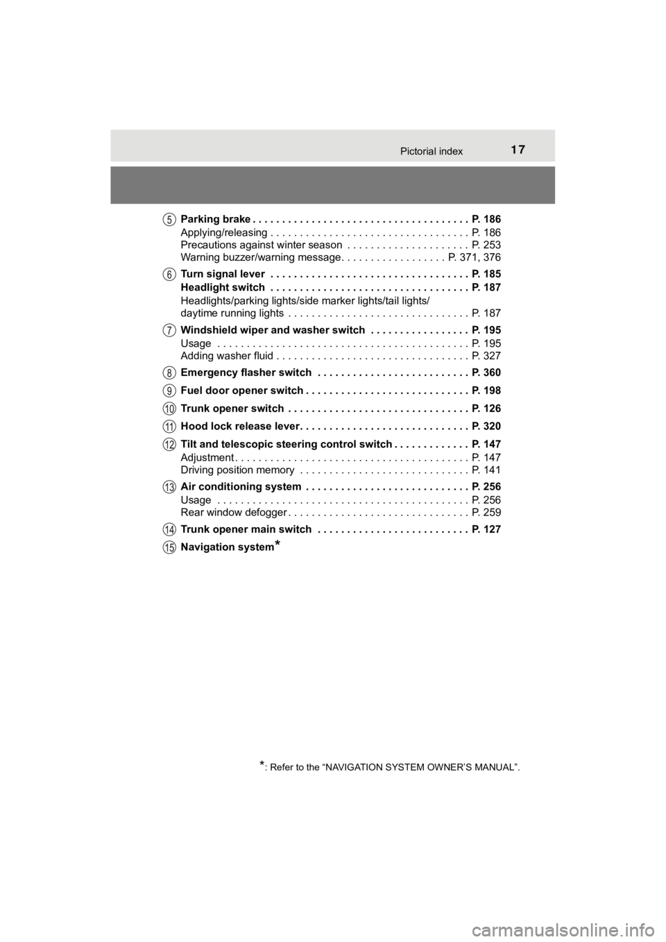
MIRAI_OM_USA_OM62025UParking brake . . . . . . . . . . . . . . . . . . . . . . . . . . . . . . . . . . . . . P. 186
Applying/releasing . . . . . . . . . . . . . . . . . . . . . . . . . . . . . . . . . . P. 186
Precautions against winter season . . . . . . . . . . . . . . . . . . . . . P. 253
Warning buzzer/warning message. . . . . . . . . . . . . . . . .
. P. 371, 376
Turn signal lever . . . . . . . . . . . . . . . . . . . . . . . . . . . . . . . . . . P. 185
Headlight switch . . . . . . . . . . . . . . . . . . . . . . . . . . . . . . . . . . P. 187
Headlights/parking lights/side marker lights/tail lights/
daytime running lights . . . . . . . . . . . . . . . . . . . . . . . . . . . . . . . P. 187
Windshield wiper and washer switch . . . . . . . . . . . . . . . . . P. 195
Usage . . . . . . . . . . . . . . . . . . . . . . . . . . . . . . . . . . . . . . . . . . . P. 195
Adding washer fluid . . . . . . . . . . . . . . . . . . . . . . . . . . . . . . . . . P. 327
Emergency flasher switch . . . . . . . . . . . . . . . . . . . . . . . . . . P. 360
Fuel door opener switch . . . . . . . . . . . . . . . . . . . . . . . . . . . . P. 198
Trunk opener switch . . . . . . . . . . . . . . . . . . . . . . . . . . . . . . . P. 126
Hood lock release lever. . . . . . . . . . . . . . . . . . . . . . . . . . . . . P. 320
Tilt and telescopic steering control switch . . . . . . . . . . . . . P. 147
Adjustment . . . . . . . . . . . . . . . . . . . . . . . . . . . . . . . . . . . . . . . . P. 147
Driving position memory . . . . . . . . . . . . . . . . . . . . . . . . . . . . . P. 141
Air conditioning system . . . . . . . . . . . . . . . . . . . . . . . . . . . . P. 256
Usage . . . . . . . . . . . . . . . . . . . . . . . . . . . . . . . . . . . . . . . . . . . P. 256
Rear window defogger . . . . . . . . . . . . . . . . . . . . . . . . . . . . . . . P. 259
Trunk opener main switch . . . . . . . . . . . . . . . . . . . . . . . . . . P. 127
Navigation system
*
*: Refer to the “NAVIGATION SYSTEM OWNER’S MANUAL”.
Page 83 of 464
832. Fuel cell vehicle
2
Fuel cell system
MIRAI_OM_USA_OM62025U
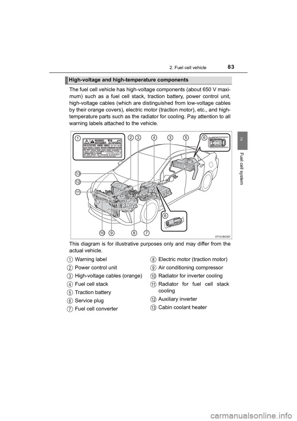
The fuel cell vehicle has high-voltage components (about 650 V m axi-
mum) such as a fuel cell stack, traction battery, power control unit,
high-voltage cables (which are di stinguished from low-voltage cables
by their orange covers), electric motor (traction motor), etc., and high-
temperature parts such as the radiator for cooling. Pay attenti on to all
warning labels attached to the vehicle.
This diagram is for illustrative purposes only and may differ f rom the
actual vehicle.
High-voltage and high-temperature components
Warning label
Power control unit
High-voltage cables (orange)
Fuel cell stack
Traction battery
Service plug
Fuel cell converter Electric motor (traction motor)
Air conditioning compressor
Radiator for inverter cooling
Radiator for fuel cell stack
cooling
Auxiliary inverter
Cabin coolant heater
Page 85 of 464
852. Fuel cell vehicle
2
Fuel cell system
MIRAI_OM_USA_OM62025U
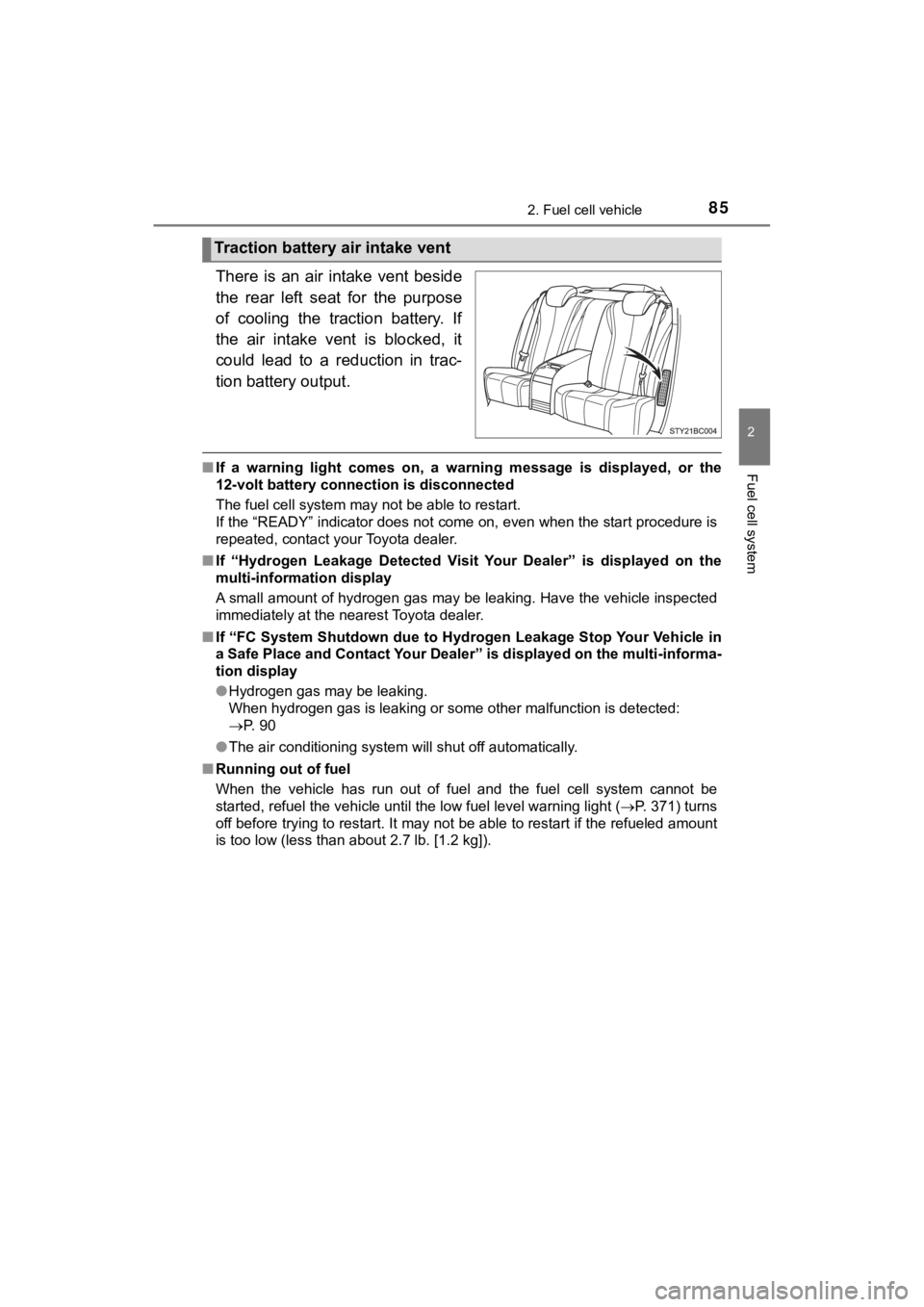
There is an air intake vent beside
the rear left seat for the purpose
of cooling the traction battery. If
the air intake vent is blocked, it
could lead to a reduction in trac-
tion battery output.
■If a warning light comes on, a warning message is displayed, or the
12-volt battery connection is disconnected
The fuel cell system may not be able to restart.
If the “READY” indicator does not come on, even when the start procedure is
repeated, contact your Toyota dealer.
■ If “Hydrogen Leakage Detected Visit Your Dealer” is displayed on the
multi-information display
A small amount of hydrogen gas may be leaking. Have the vehicle inspected
immediately at the nearest Toyota dealer.
■ If “FC System Shutdown due to Hydrogen Leakage Stop Your Vehicle in
a Safe Place and Contact Your Dealer” is displayed on the multi -informa-
tion display
● Hydrogen gas may be leaking.
When hydrogen gas is leaking or some other malfunction is detected:
P. 90
● The air conditioning system will shut off automatically.
■ Running out of fuel
When the vehicle has run out of fuel and the fuel cell system c annot be
started, refuel the vehicle until the low fuel level warning li ght (P. 371) turns
off before trying to restart. It may not be able to restart if the refueled amount
is too low (less than about 2.7 lb. [1.2 kg]).
Traction battery air intake vent
Page 95 of 464
952. Fuel cell vehicle
2
Fuel cell system
MIRAI_OM_USA_OM62025U
◆Using Eco drive mode
Using Eco drive mode (P. 181) makes torque generation less
aggressive than normal when stepping on the accelerator pedal,
leading to improvement in fuel economy.
Also, is displayed on the air conditioning screen, indicating
the switch to ECO HEAT/COOL mode ( P. 2 5 8 ) .
◆Air conditioning system on/off
● Turn off the air conditioning system operation switch except
when necessary to help curb fuel consumption.
In summer: When the ambient temperature is high, use the recircu -
lated air mode. This decreases the load on the air con-
ditioning system.
In winter: Avoid excess heating. Use the seat heater to minimize the need for cabin heating ( P. 266).
● By pushing , ECO HEAT/COOL mode is turned on. This
helps curb fuel consumption even with the air conditioning syst em
turned on.
◆Checking tire inflation pressure
Make sure to check the tire inflation pressure frequently. Impr oper
tire inflation pressure can cause poor fuel economy.
Additionally, snow tires have mo re rolling friction and their use on
dry roads lead to poor fuel economy. Use tires that are appropr iate
for the season.
◆Luggage
Avoid carrying unnecessary luggage and unload excess weight in
order avoid poor fuel economy. Installing a large roof rack wil l also
reduce fuel economy.
Page 103 of 464

1033. Instrument cluster
3
Instrument cluster
MIRAI_OM_USA_OM62025U
Power restriction indicator
Blue: The fuel cell system output power is restricted, because the
coolant temperature is low.
Amber: The fuel cell system output power is restricted, because the
coolant temperature is high.
Outside temperature
Displays the outside temperature within the range of -40°F (-40 °C)
to 122°F (50°C).
Low outside temperature indicator flashes when the ambient tem-
perature is 37°F (3°C) or lower.
Driving range distance
Displays the estimated maximum distance that can be driven with
the quantity of fuel remaining. • Displays the possible driving d istance computed from the fuel
consumption studied f rom the driving history and the current
remaining amount of fuel. The ac tual possible driving distance
may differ as fuel consumpti on changes, depending on driving
environment (weather, traffic, etc.) and conditions (sudden acc el-
eration, air conditioning, etc.).
• When only a small amount of fuel is added to the hydrogen tanks, the display may not be updated.
Speedometer
Displays the vehicle speed.
Odometer and trip meter
Odometer:
Displays the total distance the vehicle has been driven.
Trip meter:
Displays the distance the vehicl e has been driven since the met er
was last reset.
Trip meters “A” and “B” can be used to record and display diffe rent
distances independently.
Distance after start:
Displays the distance driven afte r the fuel cell system was started.
Blank:
A blank is displayed.
Page 181 of 464
1815-2. Driving procedures
5
Driving
MIRAI_OM_USA_OM62025U
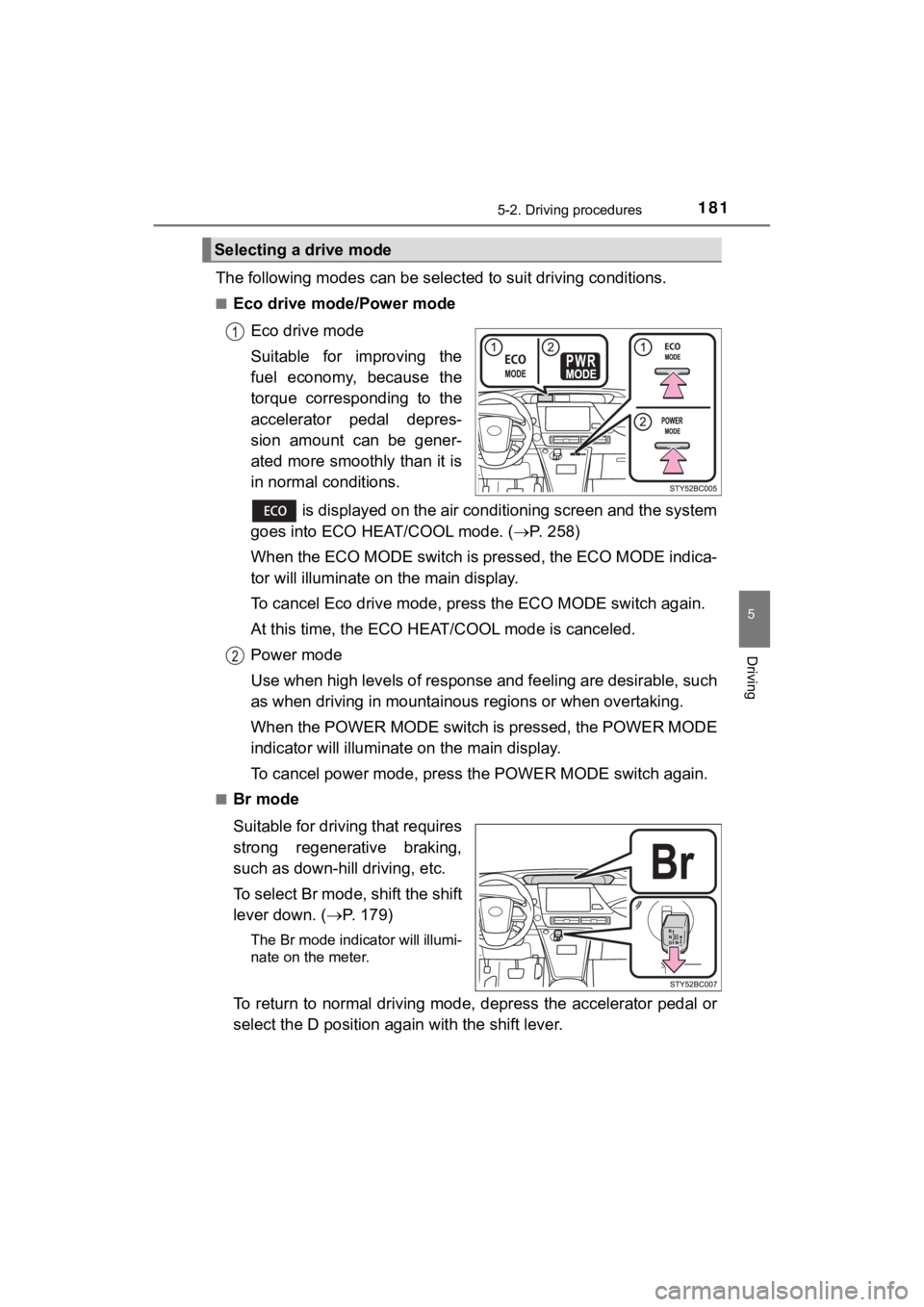
The following modes can be selected to suit driving conditions.
■Eco drive mode/Power mode
Eco drive mode
Suitable for improving the
fuel economy, because the
torque corresponding to the
accelerator pedal depres-
sion amount can be gener-
ated more smoothly than it is
in normal conditions.
is displayed on the air conditioning screen and the system
goes into ECO HEAT/COOL mode. ( P. 258)
When the ECO MODE switch is pressed, the ECO MODE indica-
tor will illuminate on the main display.
To cancel Eco drive mode, pre ss the ECO MODE switch again.
At this time, the ECO HE AT/COOL mode is canceled.
Power mode
Use when high levels of response and feeling are desirable, such
as when driving in mountainous regions or when overtaking.
When the POWER MODE switch is pressed, the POWER MODE
indicator will illuminate on the main display.
To cancel power mode, press the POWER MODE switch again.
■Br mode
Suitable for driving that requires
strong regenerative braking,
such as down-hill driving, etc.
To select Br mode, shift the shift
lever down. ( P. 179)
The Br mode indicator will illumi-
nate on the meter.
To return to normal driving mode, depress the accelerator pedal or
select the D position again with the shift lever.
Selecting a drive mode
Page 183 of 464
1835-2. Driving procedures
5
Driving
MIRAI_OM_USA_OM62025U■
Regenerative Braking
When the shift position is in D, regenerative braking is engage d when the foot
is released from the accelerator pedal.
■ ECO HEAT/COOL mode operation for Eco drive mode
●When the ECO MODE switch is pressed, the system switches over t o ECO
HEAT/COOL mode. ( P. 261) During the use of Eco drive mode, only the
ECO HEAT/COOL mode can be canceled.
● When it is desired to improve the effectiveness of the air cond itioning sys-
tem, perform the following operations.
• Adjust the temperature settings and airflow mode.
• Press of the air conditioning operation panel ( P. 256) and can-
cel the ECO HEAT/COOL mode, or cancel Eco drive mode.
■ Power mode automatic deactivation
Power mode is automatically deactivated if the power switch is turned off after
driving in power mode.
■ Shifting from P on a slope
When changing to another position from P when parked on a slope in the P
position, vibrations may be felt.
WARNING
■When driving on slippery road surfaces
Do not accelerate or shift the shift position suddenly.
Sudden changes in regenerative braking may cause the vehicle to spin or
skid, resulting in an accident.
■ For the shift lever
Do not remove the shift lever knob or use anything but a genuin e Toyota
shift lever knob. Also, do not hang anything on the shift lever .
Doing so could prevent the shift lever from returning to positi on, causing
unexpected accidents to occur when the vehicle is in motion.
■ P position switch
Do not press the P position switch while the vehicle is moving.
If the P position switch is pressed when driving at very low speeds (for
example, directly before stopping the vehicle), the vehicle may stop sud-
denly when the shift position switches to P, which could lead t o an accident.
Page 219 of 464

2195-5. Using the driving support systems
5
Driving
MIRAI_OM_USA_OM62025U
■Temporary cancelation of the LDA system functions
If any of the following occurs, the LDA system functions will b e temporarily
canceled. The functions will resume after the necessary operati ng conditions
have returned.
● The turn signal lever is operated.
● The vehicle speed deviates from the operating range of the LDA system
functions.
● When the lane lines cannot be recognized while driving.
● When the lane departure warning function is activated.
The lane departure warning function will not operate again for a several sec-
onds after it has been activated, even if the vehicle leaves th e lane again.
■ Alert buzzer for lane departure alert
Depending on the audio system sound level or air conditioning f an noise
while the audio system or air conditioning system is in use, it may be difficult
to hear the alert buzzer.
■ After the vehicle has been parked in the sun
The LDA system may not be available and a warning message is displayed
for a while after driving has started. When the temperature in the cabin
decreases and the temperature around the camera sensor ( P. 2 1 6 )
becomes suitable for its operation, turn the LDA switch on agai n after a
short time.
■ If there are lane markers on only one side of the vehicle
The lane departure alert will not operate for the side on which lane markers
could not be recognized.
Page 229 of 464

2295-5. Using the driving support systems
5
Driving
MIRAI_OM_USA_OM62025U●
The following situations may occur during use.
• Depending on the shape of the obstacle and other factors, the detection
distance may shorten, or detection may be impossible.
• Obstacles may not be detected if they are too close to the sen sor.
• There will be a short delay between obstacle detection and dis play. Even
at slow speeds, there is a possibility that the obstacle will c ome within the
sensor’s detection areas before the display is shown and the bu zzer
sounds.
• Thin posts or objects lower than the sensor may not be detecte d when
approached, even if they have been detected once.
• It might be difficult to hear beeps due to the volume of audio system or air
flow noise of the air conditioning system.
■ If “Clean Parking Assist Sensor” is displayed on the multi-information
display
A sensor may be dirty or covered with snow or ice. In such case s, if it is
removed from the sensor, the system should return to normal.
Also, due to the sensor being frozen at low temperatures, a mal function dis-
play may appear or an obstacle may not be detected. If the sens or thaws out,
the system should return to normal.
■ If “Parking Assist Malfunction” is displayed on the multi-information dis-
play
Depending on the malfunction of the sensor, the device may not be working
normally.
Have the vehicle inspected by your Toyota dealer.
■ Customization
Some functions can be customized.
(Customizable features: P. 440)
■ Certification for the intuitive parking assist
This device complies with Part 15 of the FCC Rules. Operation i s subject to
the following two conditions: (1) This device may not cause har mful interfer-
ence, and (2) This device must accept any interference received, including
interference that may cause undesired operation.