weight TOYOTA MIRAI 2022 User Guide
[x] Cancel search | Manufacturer: TOYOTA, Model Year: 2022, Model line: MIRAI, Model: TOYOTA MIRAI 2022Pages: 556, PDF Size: 17.34 MB
Page 407 of 556
4077-3. Do-it-yourself maintenance
Owners Manual_USA_M62084_en
7
Maintenance and care
■The tire pressure warning
system must be initialized
in the following circum-
stances:
When the tire inflation pres-
sure is changed such as
when changing traveling
speed or load weight.
When the tire inflation pres-
sure is changed such as
when the tire size is changed.
When rotating the tires.
After performing the transmit-
ter ID code registration proce-
dure. ( P.409) When the tire pressure warning
system is initialized, the current
tire inflation pressure is set as
the benchmark pressure.
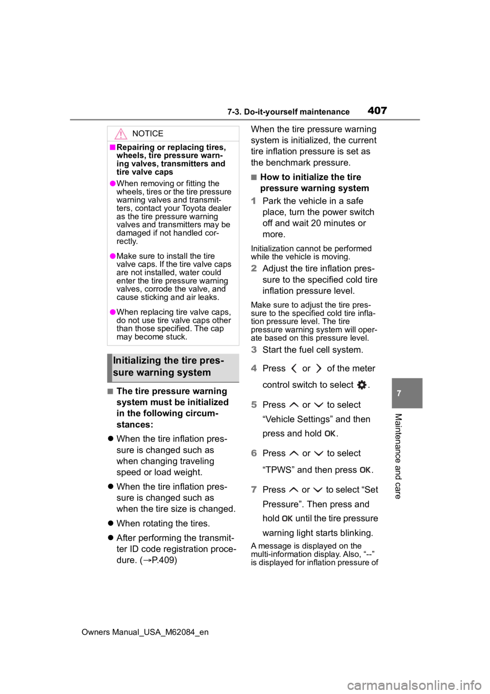
■How to initialize the tire
pressure warning system
1 Park the vehicle in a safe
place, turn the power switch
off and wait 20 minutes or
more.
Initialization cannot be performed
while the vehicle is moving.
2Adjust the tire inflation pres-
sure to the specified cold tire
inflation pressure level.
Make sure to adjust the tire pres-
sure to the specifie d cold tire infla-
tion pressure level. The tire
pressure warning system will oper-
ate based on this pressure level.
3Start the fuel cell system.
4 Press or of the meter
control switch to select .
5 Press or to select
“Vehicle Settings” and then
press and hold .
6 Press or to select
“TPWS” and then press .
7 Press or to select “Set
Pressure”. Then press and
hold until the tire pressure
warning light starts blinking.
A message is displayed on the
multi-information di splay. Also, “--”
is displayed for inflation pressure of
NOTICE
■Repairing or replacing tires,
wheels, tire pressure warn-
ing valves, transmitters and
tire valve caps
●When removing or fitting the
wheels, tires or the tire pressure
warning valves and transmit-
ters, contact your Toyota dealer
as the tire pr essure warning
valves and transmitters may be
damaged if not handled cor-
rectly.
●Make sure to install the tire
valve caps. If the tire valve caps
are not installed, water could
enter the tire pressure warning
valves, corrode the valve, and
cause sticking and air leaks.
●When replacing ti re valve caps,
do not use tire valve caps other
than those specified. The cap
may become stuck.
Initializing the tire pres-
sure warning system
Page 416 of 556
4167-3. Do-it-yourself maintenance
Owners Manual_USA_M62084_en
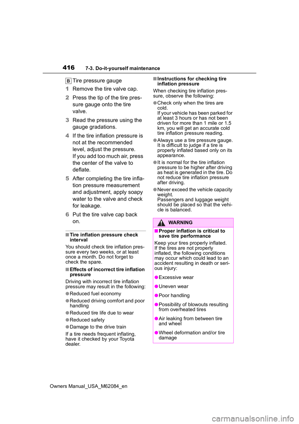
Tire pressure gauge
1 Remove the tire valve cap.
2 Press the tip of the tire pres-
sure gauge onto the tire
valve.
3 Read the pressure using the
gauge gradations.
4 If the tire inflation pressure is
not at the recommended
level, adjust the pressure.
If you add too much air, press
the center of the valve to
deflate.
5 After completing the tire infla-
tion pressure measurement
and adjustment, apply soapy
water to the valve and check
for leakage.
6 Put the tire valve cap back
on.
■Tire inflation pressure check
interval
You should check tire inflation pres-
sure every two weeks, or at least
once a month. Do not forget to
check the spare.
■Effects of incorrect tire inflation
pressure
Driving with incorrect tire inflation
pressure may result in the following:
●Reduced fuel economy
●Reduced driving comfort and poor
handling
●Reduced tire life due to wear
●Reduced safety
●Damage to the drive train
If a tire needs frequent inflating,
have it checked by your Toyota
dealer.
■Instructions for checking tire
inflation pressure
When checking tire inflation pres-
sure, observe the following:
●Check only when the tires are
cold.
If your vehicle has been parked for
at least 3 hours or has not been
driven for more than 1 mile or 1.5
km, you will get an accurate cold
tire inflation pressure reading.
●Always use a tire pressure gauge.
It is difficult to j udge if a tire is
properly inflated based only on its
appearance.
●It is normal for the tire inflation
pressure to be higher after driving
as heat is generated in the tire. Do
not reduce tire inflation pressure
after driving.
●Never exceed the vehicle capacity
weight.
Passengers and luggage weight
should be placed so that the vehi-
cle is balanced.
WARNING
■Proper inflation is critical to
save tire performance
Keep your tires properly inflated.
If the tires are not properly
inflated, the following conditions
may occur which could lead to an
accident resulting in death or seri-
ous injury:
●Excessive wear
●Uneven wear
●Poor handling
●Possibility of blowouts resulting
from overheated tires
●Air leaking from between tire
and wheel
●Wheel deformation and/or tire
damage
Page 418 of 556
4187-3. Do-it-yourself maintenance
Owners Manual_USA_M62084_en
Use only Toyota wheel nuts
and wheel nut wrenches
designed for use with your
aluminum wheels.
When rotating, repairing or
changing your tires, check
that the wheel nuts are still
tight after driving 1000 miles
(1600 km).
Be careful not to damage the
aluminum wheels when using
tire chains.
Use only Toyota genuine bal-
ance weights or equivalent
and a plastic or rubber ham-
mer when balancing your
wheels.
WARNING
■When replacing wheels
●Do not use wheels that are a dif-
ferent size from those recom-
mended in the Owner’s Manual,
as this may result in a loss of
handling control.
●Never use an inner tube in a
leaking wheel which is designed
for a tubeless tire.
Doing so may result in an acci-
dent, causing death or serious
injury.
■When installing the wheel
nuts
Never use oil or grease on the
wheel bolts or wheel nuts. Oil and
grease may cause the wheel nuts
to be excessively tightened, lead-
ing to bolt or disc wheel damage.
In addition, the oil or grease can
cause the wheel nuts to loosen
and the wheel may fall off, caus-
ing an accident and resulting in
death or serious injury. Remove
any oil or grease from the wheel
bolts or wheel nuts.
■Use of defective wheels pro-
hibited
Do not use cracked or deformed
wheels. Doing so could cause the
tire to leak air during driving, pos-
sibly causing an accident.
NOTICE
■Replacing tire pressure warn-
ing valves and transmitters
●Because tire repair or replace-
ment may affect the tire pres-
sure warning valves and
transmitters, make sure to have
tires serviced by your Toyota
dealer or other qualified service
shop. In addition, make sure to
purchase your tire pressure
warning valves and transmit-
ters at your Toyota dealer.
●Ensure that only genuine Toyota
wheels are used on your vehi-
cle.
Tire pressure warning valves
and transmitters may not work
properly with non-genuine
wheels.
Aluminum wheel precau-
tions
Page 482 of 556
4829-1. Specifications
Owners Manual_USA_M62084_en
9-1.Specifications
*1: Unladen vehicles
*2: Vehicles without electronic sunshade
*3: Vehicles with electronic sunshade
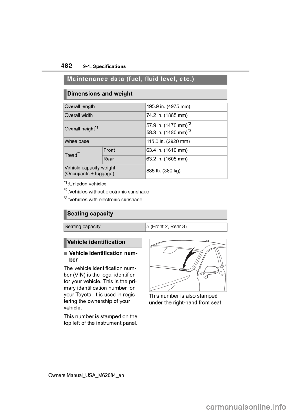
■Vehicle identification num-
ber
The vehicle identification num-
ber (VIN) is the legal identifier
for your vehicle. This is the pri-
mary identification number for
your Toyota. It is used in regis-
tering the ownership of your
vehicle.
This number is stamped on the
top left of the instrument panel. This number is also stamped
under the right-hand front seat.
Maintenance data (fuel,
fluid level, etc.)
Dimensions and weight
Overall length195.9 in. (4975 mm)
Overall width74.2 in. (1885 mm)
Overall height*157.9 in. (1470 mm)*2
58.3 in. (1480 mm)*3
Wheelbase115.0 in. (2920 mm)
Tread*1Front63.4 in. (1610 mm)
Rear63.2 in. (1605 mm)
Vehicle capacity weight
(Occupants + luggage)835 lb. (380 kg)
Seating capacity
Seating capacity5 (Front 2, Rear 3)
Vehicle identification
Page 492 of 556
4929-1. Specifications
Owners Manual_USA_M62084_enheat buildup and possible tire fail- ure.
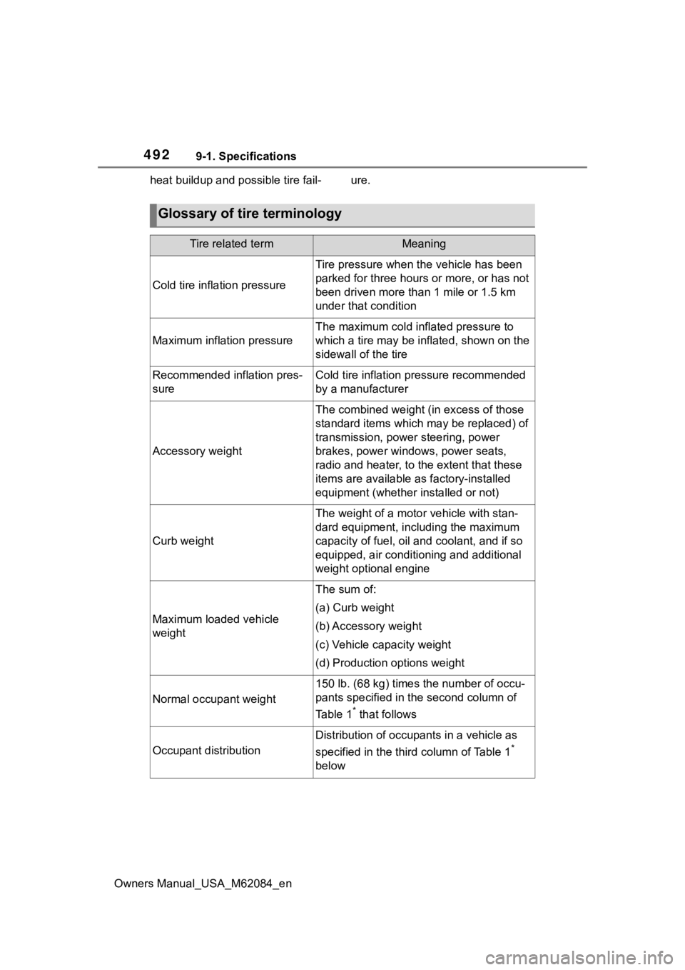
Glossary of tire terminology
Tire related termMeaning
Cold tire inflation pressure
Tire pressure when the vehicle has been
parked for three hours or more, or has not
been driven more than
1 mile or 1.5 km
under that condition
Maximum inflation pressure
The maximum cold inf lated pressure to
which a tire may be inflated, shown on the
sidewall of the tire
Recommended inflation pres-
sureCold tire inflation pressure recommended
by a manufacturer
Accessory weight
The combined weight (in excess of those
standard items which may be replaced) of
transmission, power steering, power
brakes, power windows, power seats,
radio and heater, to the extent that these
items are available as factory-installed
equipment (whether installed or not)
Curb weight
The weight of a moto r vehicle with stan-
dard equipment, including the maximum
capacity of fuel, oil and coolant, and if so
equipped, air conditioning and additional
weight optional engine
Maximum loaded vehicle
weight
The sum of:
(a) Curb weight
(b) Accessory weight
(c) Vehicle capacity weight
(d) Production options weight
Normal occupant weight
150 lb. (68 kg) times the number of occu-
pants specified in the second column of
Ta b l e 1
* that follows
Occupant distribution
Distribution of occupants in a vehicle as
specified in the third column of Table 1
*
below
Page 493 of 556
4939-1. Specifications
Owners Manual_USA_M62084_en
9
Vehicle specifications
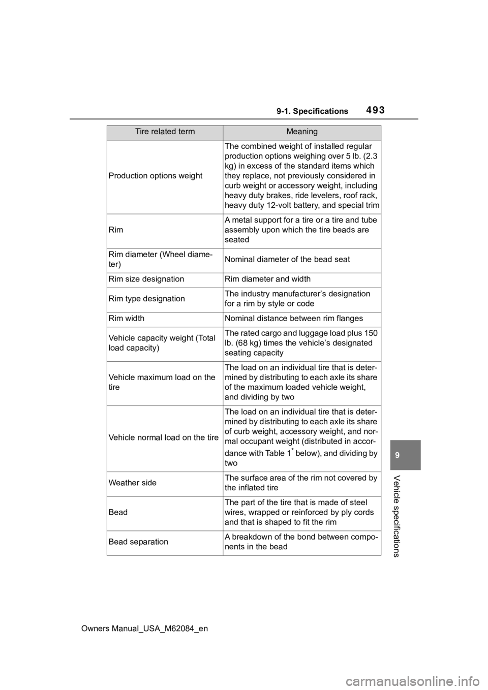
Production options weight
The combined weight of installed regular
production options weighing over 5 lb. (2.3
kg) in excess of the standard items which
they replace, not previously considered in
curb weight or accessory weight, including
heavy duty brakes, ride levelers, roof rack,
heavy duty 12-volt battery, and special trim
Rim
A metal support for a tire or a tire and tube
assembly upon which the tire beads are
seated
Rim diameter (Wheel diame-
ter)Nominal diameter o f the bead seat
Rim size designationRim diameter and width
Rim type designationThe industry manufacturer’s designation
for a rim by style or code
Rim widthNominal distance between rim flanges
Vehicle capacity weight (Total
load capacity)The rated cargo and luggage load plus 150
lb. (68 kg) times the vehicle’s designated
seating capacity
Vehicle maximum load on the
tire
The load on an individua l tire that is deter-
mined by distributing to each axle its share
of the maximum loaded vehicle weight,
and dividing by two
Vehicle normal load on the tire
The load on an individua l tire that is deter-
mined by distributing to each axle its share
of curb weight, accessory weight, and nor-
mal occupant weight (distributed in accor-
dance with Table 1
* below), and dividing by
two
Weather sideThe surface area of the rim not covered by
the inflated tire
Bead
The part of the tire that is made of steel
wires, wrapped or reinforced by ply cords
and that is shaped to fit the rim
Bead separationA breakdown of the bond between compo-
nents in the bead
Tire related termMeaning
Page 495 of 556
4959-1. Specifications
Owners Manual_USA_M62084_en
9
Vehicle specifications
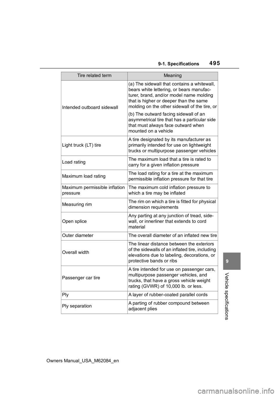
Intended outboard sidewall
(a) The sidewall that c ontains a whitewall,
bears white lettering , or bears manufac-
turer, brand, and/or model name molding
that is higher or deeper than the same
molding on the other s idewall of the tire, or
(b) The outward facing sidewall of an
asymmetrical tire that has a particular side
that must always face outward when
mounted on a vehicle
Light truck (LT) tire
A tire designated by its manufacturer as
primarily intended for use on lightweight
trucks or multipurpose passenger vehicles
Load ratingThe maximum load that a tire is rated to
carry for a given inflation pressure
Maximum load ratingThe load rating for a tire at the maximum
permissible inflation pressure for that tire
Maximum permissible inflation
pressureThe maximum cold inf lation pressure to
which a tire may be inflated
Measuring rimThe rim on which a tire is fitted for physical
dimension requirements
Open splice
Any parting at any junction of tread, side-
wall, or innerliner that extends to cord
material
Outer diameterThe overall diameter of an inflated new tire
Overall width
The linear distance between the exteriors
of the sidewalls of an inflated tire, including
elevations due to labeling, decorations, or
protective bands or ribs
Passenger car tire
A tire intended for use on passenger cars,
multipurpose passenger vehicles, and
trucks, that have a gross vehicle weight
rating (GVWR) of 10,000 lb. or less.
PlyA layer of rubber-coated parallel cords
Ply separationA parting of rubber compound between
adjacent plies
Tire related termMeaning
Page 510 of 556
5109-3. Initialization
Owners Manual_USA_M62084_en
9-3.Initialization
*: If equipped
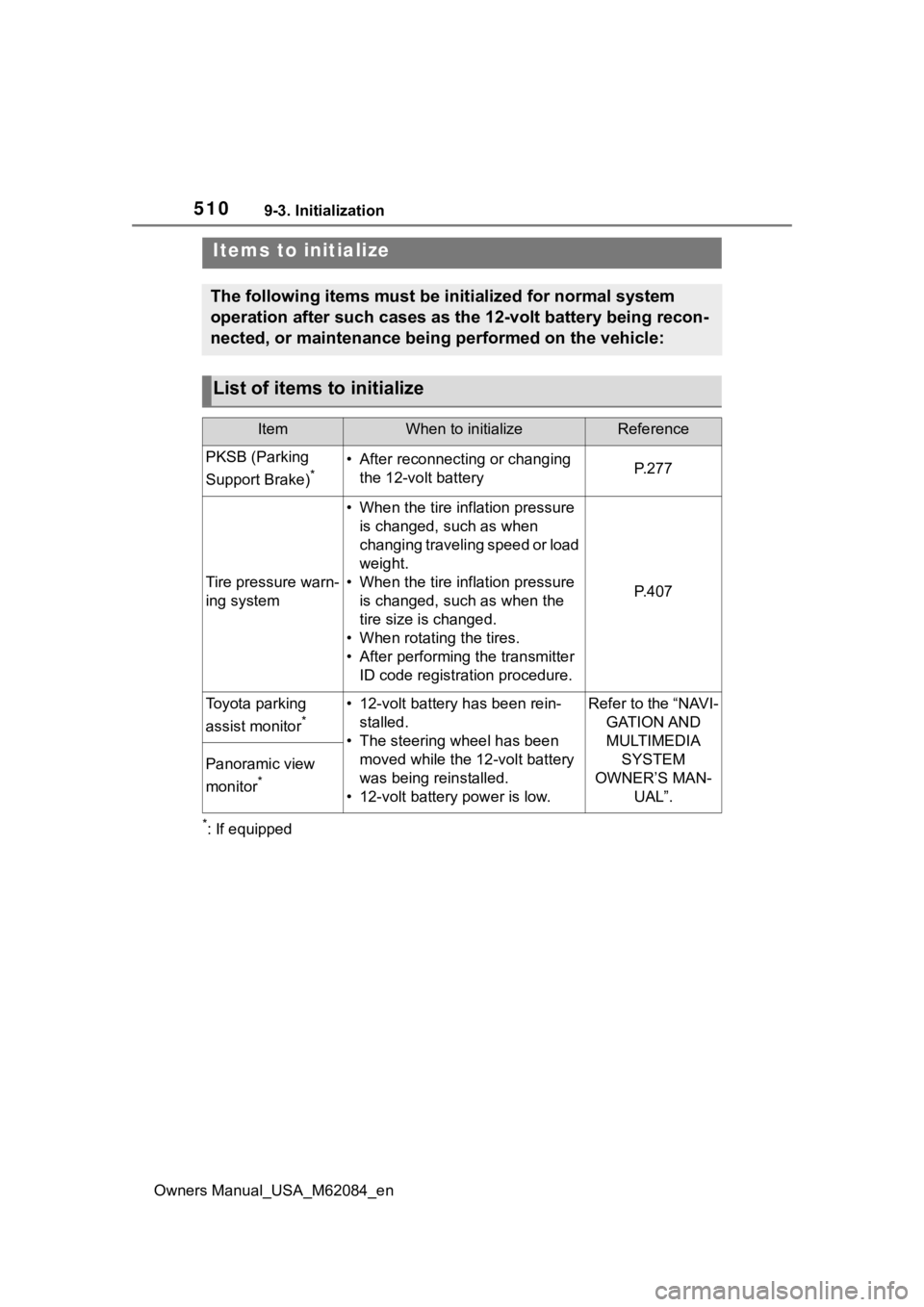
Items to initialize
The following items must be initialized for normal system
operation after such cases as the 12-volt battery being recon-
nected, or maintenance being performed on the vehicle:
List of items to initialize
ItemWhen to initializeReference
PKSB (Parking
Support Brake)
*• After reconnecting or changing the 12-volt batteryP.277
Tire pressure warn-
ing system
• When the tire inflation pressure is changed, such as when
changing traveling speed or load
weight.
• When the tire inflation pressure is changed, such as when the
tire size is changed.
• When rotating the tires.
• After performing the transmitter
ID code registration procedure.
P.407
Toyota parking
assist monitor
*
• 12-volt battery has been rein-
stalled.
• The steering wheel has been moved while the 12-volt battery
was being reinstalled.
• 12-volt battery power is low.Refer to the “NAVI- GATION AND
MULTIMEDIA SYSTEM
OWNER’S MAN- UAL”.
Panoramic view
monitor
*
Page 540 of 556
540Alphabetical Index
Owners Manual_USA_M62084_en
Intuitive parking assist .. 260, 444
LTA (Lane Tracing Assist) ... 223, 227, 444
Open door ......... ........... 122, 124
Open window ....................... 157
PCS (Pre-Collision System) . 444
PKSB (Parking Support Brake) ........................................... 445
Pre-collision braking ............. 212
Pre-collision warning ............ 212
RCD (Rear Camera Detection) ........................................... 445
RCTA (Rear Cross Traffic Alert) ........................................... 445
Seat belt ............................... 448
SRS airbag ........................... 442
Vehicle sway warning function (LTA) ................................... 233
Warning label ............................ 79
Warning lights .................. 93, 441 ABS ...................................... 443
Brake hold operated indicator........................................... 446
Brake Override System ........ 446
Brake system ....................... 441
Charging system .................. 442
Drive-Start Control ............... 446
Electric power steering ......... 443
Fuel cell system overheat .... 442
High coolant temperature ..... 442
Hydrogen leak ...................... 441
Intuitive parking assist OFF indi- cator ................................... 444
Low fuel level ....................... 447
LTA indicator ......................... 444
Parking brake indicator ........ 447
PKSB OFF indicato r ............. 445
Pop Up Hood........................ 443
Pre-collision system ............. 444
RCD OFF indicator............... 445
RCTA OFF indicator ............. 445
Seat belt reminder light ........ 448 Slip indicator .........................446
SRS airbag ...........................442
Tire pressure ......
..................447
Warning messages .................451
Warning reflector ....................352
Washer .....................................197 Adding ..................................399
Preparing and checking before winter ..................................320
Switch ...................................197
Washing and waxing ..............380
Weight Cargo capacity .....................170
Load limits ............................170
Weight ..................................482
Wheels .....................................417 Replacing wheels ................. 411
Size ......................................487
Window lock switch ...............158
Windows Power windows ....................156
Rear window defogger .327, 334
Washer .................................197
Windshield defogger ......326, 334
Windshield wipers ..................197 Rain-sensing windshield wipers...........................................197
Rest position.........................200
Winter driving tips ..................320
Wireless charger.....................357
Wireless remote control......... 119 Battery-Saving Function .......131
Locking/Unlocking ................ 119
Replacing the battery ...........423
?
For infor mation regarding the equipment listed
below, refer to the “NAVI-
GATION AND MULTIME-