immobilizer TOYOTA MIRAI 2022 Owners Manual
[x] Cancel search | Manufacturer: TOYOTA, Model Year: 2022, Model line: MIRAI, Model: TOYOTA MIRAI 2022Pages: 556, PDF Size: 17.34 MB
Page 2 of 556
2
Owners Manual_USA_M62084_enTABLE OF CONTENTS
For your information...................
6
Reading this manual ................ 11
How to search .......................... 12
Pictorial index .......................... 14
1-1. For safe use Before driving ................... 26
For safe driving ................ 27
Seat belts ......................... 29
SRS airbags ..................... 34
Pop Up Hood ................... 43
Front passenger occupant classification system ...... 46
1-2. Child safety Riding with children .......... 51
Child restraint systems..... 52
1-3. Emergency assistance Safety Connect ................ 65
1-4. Theft deterrent system Immobilizer system .......... 69
Alarm................................ 70
Theft prevention labels (U.S.A.) .......................... 72
2-1. Fuel cell vehicle Fuel cell vehicle characteris-tics .................................. 74
Fuel cell vehicle precautions ....................................... 79
Fuel cell vehicle driving tips ....................................... 893-1. Instrument cluster
Warning lights and indicators....................................... 92
Gauges and meters .......... 97
Multi-information display 100
Head-up display ............ 107
Energy monitor/ consumption
screen/air purification
screen.......................... 111
4-1. Key information Keys .............................. 118
4-2. Opening, closing and lock- ing the doors and trunk
Doors ............................. 121
Trunk ............................. 126
Smart key system .......... 130
4-3. Adjusting the seats Front seats .................... 135
Driving position memory 136
Head restraints .............. 139
4-4. Adjusting the steering wheel and mirrors
Steering wheel............... 141
Inside rear view mirror ... 143
Digital Rearview Mirror .. 144
Outside rear view mirrors .................................... 154
4-5. Opening, closing the win- dows
1For safety and security
2Fuel cell system
3
Vehicle status
information and
indicators
4Before driving
Page 25 of 556

25
Owners Manual_USA_M62084_en
1
1
For safety and security
For safety and security
1-1. For safe useBefore driving ................. 26
For safe driving .............. 27
Seat belts ....................... 29
SRS airbags ................... 34
Pop Up Hood ................. 43
Front passenger occupant classification system .... 46
1-2. Child safety Riding with children ........ 51
Child restraint systems... 52
1-3. Emergency assistance Safety Connect .............. 65
1-4. Theft deterrent system Immobilizer sys tem ........69
Alarm.............................. 70
Theft prevention labels (U.S.A.) ........................ 72
Page 69 of 556
691-4. Theft deterrent system
Owners Manual_USA_M62084_en
1
For safety and security
1-4.Theft deterrent system
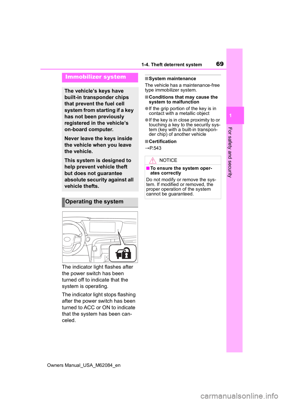
The indicator light flashes after
the power switch has been
turned off to indicate that the
system is operating.
The indicator light stops flashing
after the power switch has been
turned to ACC or ON to indicate
that the system has been can-
celed.
■System maintenance
The vehicle has a maintenance-free
type immobilizer system.
■Conditions that may cause the
system to malfunction
●If the grip portion of the key is in
contact with a metallic object
●If the key is in close proximity to or
touching a key to the security sys-
tem (key with a built-in transpon-
der chip) of another vehicle
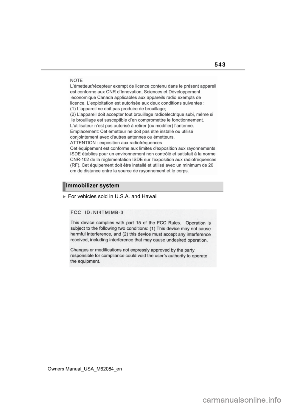
■Certification
P.543
Immobilizer system
The vehicle’s keys have
built-in transponder chips
that prevent the fuel cell
system from starting if a key
has not been previously
registered in the vehicle’s
on-board computer.
Never leave the keys inside
the vehicle when you leave
the vehicle.
This system is designed to
help prevent vehicle theft
but does not guarantee
absolute security against all
vehicle thefts.
Operating the system
NOTICE
■To ensure the system oper-
ates correctly
Do not modify or remove the sys-
tem. If modified or removed, the
proper operation of the system
cannot be guaranteed.
Page 132 of 556

1324-2. Opening, closing and locking the doors and trunk
Owners Manual_USA_M62084_en
●Electronic keys that will not be
used for long periods of time can
be set to the battery-saving mode
in advance.
■Conditions affecting operation
The smart key system uses weak
radio waves. In the following situa-
tions, the communication between
the electronic key and the vehicle
may be affected, preventing the
smart key system, wireless remote
control and immobilizer system from
operating properly. (Ways of coping:
P.468)
●When the electronic key battery is
depleted
●Near a TV tower, electric power
plant, gas station , radio station,
large display, airpo rt or other facil-
ity that generates strong radio
waves or electrical noise
●When carrying a portable radio,
cellular phone, cordless phone or
other wireless communication
device
●When the electronic key is in con-
tact with, or is covered by the fol-
lowing metallic objects
• Cards to which al uminum foil is
attached
• Cigarette boxes that have alumi- num foil inside
• Metallic wallets or bags
• Coins
• Hand warmers made of metal
• Media such as CDs and DVDs
●When other wireless keys (that
emit radio waves) are being used
nearby
●When carrying the electronic key
together with the following devices that emit radio waves
• Another electronic key or a wire- less key that emits radio waves
• Personal computers or personal digital assistants (PDAs)
• Digital audio players
• Portable game systems
●If window tint wit h a metallic con-
tent or metallic objects are
attached to the rear window
●When the electronic key is placed
near a battery charger or elec-
tronic devices
●When the vehicle is parked in a
pay parking spot where radio
waves are emitted.
■Note for the entry function
●Even when the electronic key is
within the effective range (detec-
tion areas), the system may not
operate properly in the following
cases:
• The electronic key is too close to the window or outside door han-
dle, near the ground, or in a high
place when the doors are locked
or unlocked.
• The electronic key is near the ground or in a high place, or too
close to the center of the rear
bumper when the trunk is opened.
• The electronic key is on the instru- ment panel, rear package tray or
floor, or in the door pockets or
glove box when the fuel cell sys-
tem is started or power switch
modes are changed.
●Do not leave the electronic key on
top of the instrument panel or near
the door pockets when exiting the
vehicle. Depending on the radio
wave reception conditions, it may
be detected by the antenna out-
side the cabin and the doors will
become lockable from the outside,
possibly trapping the electronic
key inside the vehicle.
●As long as the electronic key is
within the effective range, the
doors may be locked or unlocked
by anyone. However, only the
Page 173 of 556
1735-2. Driving procedures
Owners Manual_USA_M62084_en
5
Driving
Shutdown Due to Freezing Stop in
a Safe Place See Owner’s Man-
ual” may be displayed in the multi-
information display.
The fuel cell system is frozen and
cannot be started. Contact your Toy-
ota dealer.
●The power output will be tempo-
rarily limited until the fuel cell sys-
tem reaches full operating
temperature.
●When the traction battery is
extremely cold (below approxi-
mately -22˚F [-3 0˚C]) under the
influence of outsi de temperature,
it may not be poss ible to start the
fuel cell system. In this case, try to
start the fuel ce ll system again
after the temperat ure of the trac-
tion battery increases due to the
outside temperature increase etc.
■If the fuel cell system does not
start
●The immobilizer system may not
have been deactivated. ( P. 6 9 )
Contact your Toyota dealer.
●If a message related to start-up is
shown on the multi-information
display, read the message and fol-
low the instructions.
●Check that the fuel door is closed.
When the fuel doo r is open, the
fuel cell system cannot be started.
Close the fuel door before starting
the system. ( P.205)
■Sounds and vibrations specific
to a fuel cell vehicle
P. 7 5
■If the 12-volt battery is dis-
charged
The fuel cell system cannot be
started using the smart key system.
Refer to P.471to res tart the fuel cell
system.
■Electronic key battery depletion
P. 1 1 8
■Conditions affecting operation
P.132
■Notes for the entry function
P.132
■If “Smart Key System Malfunc-
tion See Owner’s Manual” is
displayed on the multi-informa-
tion display
The system may be malfunctioning.
Have the vehicle inspected by your
Toyota dealer immediately.
■Steering lock function
●After turning the power switch off
and opening and closing the
doors, the steeri ng wheel will be
locked due to the steering lock
function. Operating the power
switch again automatically can-
cels the steering lock.
●When the steering lock cannot be
released, “Push Power Switch
while Turning Steering Wheel in
Either Direction” will be displayed
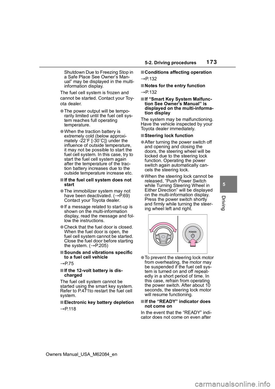
on the multi-information display.
Press the power switch shortly
and firmly while turning the steer-
ing wheel left and right.
●To prevent the steering lock motor
from overheating , the motor may
be suspended if the fuel cell sys-
tem is turned on and off repeat-
edly in a short period of time. In
this case, refrain from operating
the power switch. After about 10
seconds, the steering lock motor
will resume functioning.
■If the “READY” indicator does
not come on
In the event that the “READY” indi-
cator does not come on even after
Page 436 of 556
4368-2. Steps to take in an emergency
Owners Manual_USA_M62084_en
In the following situations, it is
not possible to be towed by another vehicle using cables or
chains, as the rear wheels may
be locked due to the parking
lock. Contact your Toyota dealer
or commercial towing service.
There is a malfunction in the
shift control system. ( P.451)
There is a malfunction in the
immobilizer system. ( P.69)
There is a malfunction in the
smart key system. ( P.468)
The 12-volt battery is dis-
charged. ( P.471)
The following may indicate a
problem with your transmission.
Contact your Toyota dealer or
commercial towing service
before towing.
The fuel cell system warning
message is shown on the
multi-information display and
the vehicle does not move.
The vehicle makes an abnor-
mal sound.
WARNING
�
Page 466 of 556
4668-2. Steps to take in an emergency
Owners Manual_USA_M62084_en
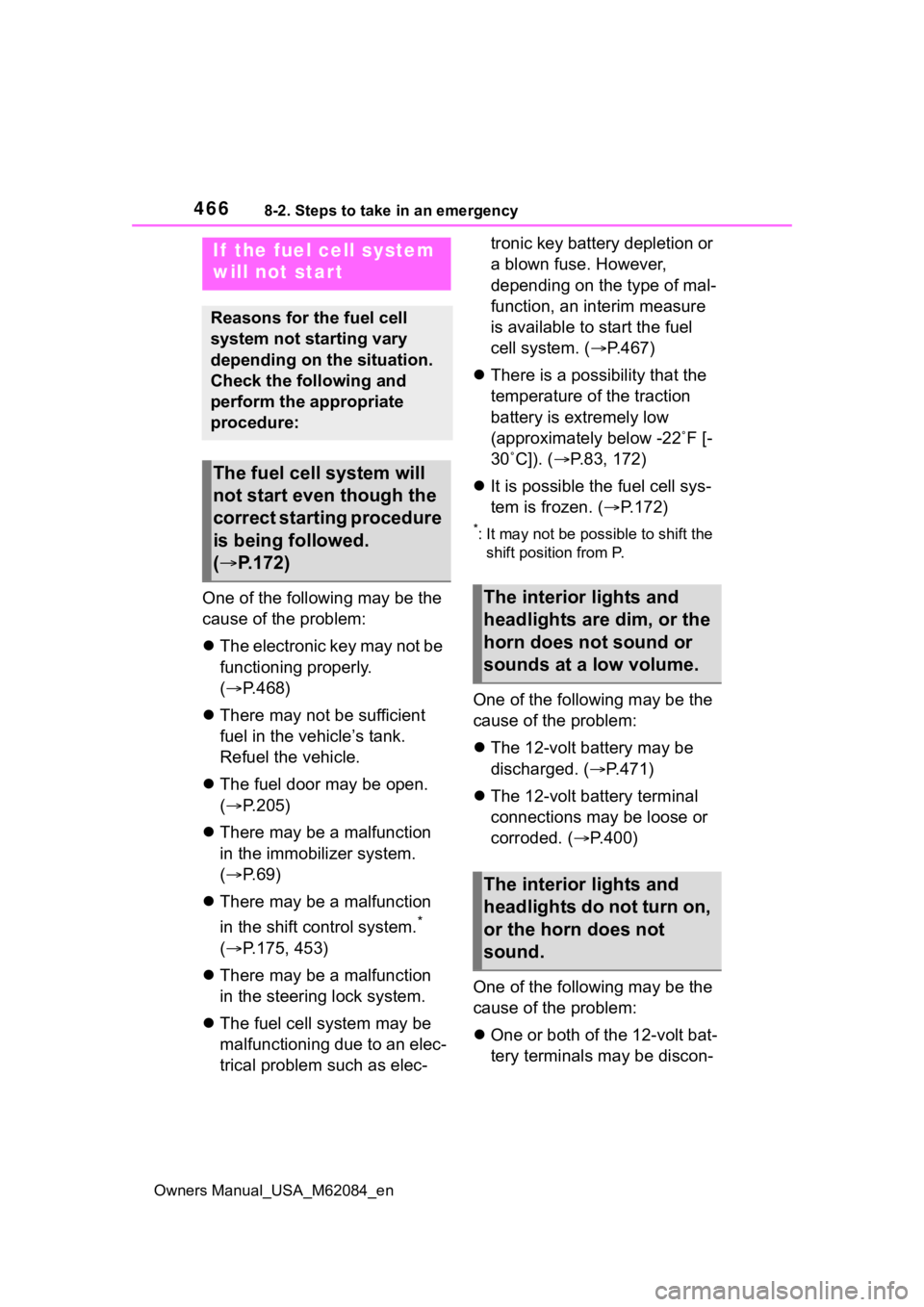
One of the following may be the
cause of the problem:
The electronic key may not be
functioning properly.
( P.468)
There may not be sufficient
fuel in the vehicle’s tank.
Refuel the vehicle.
The fuel door may be open.
( P.205)
There may be a malfunction
in the immobilizer system.
( P. 6 9 )
There may be a malfunction
in the shift control system.
*
( P.175, 453)
There may be a malfunction
in the steering lock system.
The fuel cell system may be
malfunctioning due to an elec-
trical problem such as elec- tronic key battery depletion or
a blown fuse. However,
depending on the type of mal-
function, an interim measure
is available to start the fuel
cell system. (
P.467)
There is a possibility that the
temperature of the traction
battery is extremely low
(approximately below -22˚F [-
30˚C]). ( P.83, 172)
It is possible the fuel cell sys-
tem is frozen. ( P.172)
*: It may not be possible to shift the
shift position from P.
One of the following may be the
cause of the problem:
The 12-volt battery may be
discharged. ( P.471)
The 12-volt battery terminal
connections may be loose or
corroded. ( P.400)
One of the following may be the
cause of the problem:
One or both of the 12-volt bat-
tery terminals may be discon-
If the fuel cell system
will not start
Reasons for the fuel cell
system not starting vary
depending on the situation.
Check the following and
perform the appropriate
procedure:
The fuel cell system will
not start even though the
correct starting procedure
is being followed.
( P.172)
The interior lights and
headlights are dim, or the
horn does not sound or
sounds at a low volume.
The interior lights and
headlights do not turn on,
or the horn does not
sound.
Page 532 of 556

532Alphabetical Index
Owners Manual_USA_M62084_en
Glove box ................................ 349
Glove box light ....................... 350
H
Head restraints ....................... 139
Head-up display ..................... 107 Driving information display area........................................... 107
Driving support system display area .................................... 110
Fuel cell system indicator ..... 111
HUD (Head-up display) switch ........................................... 109
Navigation system-linked display ........................................... 107
Outside temperature ............ 107
Pop-up display ..................... 110
Settings ................................ 109
Headlights Automatic High Beam system........................................... 193
Light switch .......................... 191
Replacing light bulbs ............ 429
Heated steering wheel ........... 342
Heaters Automatic air conditioning sys-tem ............................. 325, 332
Heated steering wheel ......... 342
Outside rear view mirrors ... 327, 334
Seat heaters ......................... 342
High mounted stoplight Replacing light bulbs ............ 429
High-voltage components ....... 79
Hill-start assist control .......... 315
Hood ........................................ 393 Open .................................... 393
Pop Up Hood.......................... 43
Hooks Coat hooks ........................... 362
Retaining hooks (floor mat) .... 26
Horn ......................................... 142 HUD (Head-up display) switch
...............................................109
Hydrogen detecto rs..................82
Hydrogen tanks ............74, 79, 81 Capacity ...............................483
Location ............................74, 79
Hydrogen-related components79
I
Identification Vehicle ..................................482
Ignition switch (power switch) ...............................................172
Immobilizer system ..................69
Indicators ..................................94
Initialization Electronic sunshade .............355
Items to initialize ...................510
Parking Support Brake .........277
Power windows ....................156
Tire pressure w arning system
...........................................407
Inside door handle lights .......346
Inside rear view m irror ...........143
Instrument panel light control .98
Interior lights...........................346
Intuitive parking assist...........254 Enabling/disabling the system...........................................255
Function................................254
Warning lights .......................444
Warning message.................256
Inverter coolant.......................397 Checking ..............................397
Ion filter .....................................82
J
Jack Positioning a floor jack .........393
Jam protection function Power windows ....................156
Page 538 of 556

538Alphabetical Index
Owners Manual_USA_M62084_en
Parking brake switch ............ 183
Power door lock switch ........ 124
Power switch ........................ 172
Power window switches ....... 156
Rear sunshades switch ........ 370
Rear window and outside rear view mirror defoggers switch................................... 327, 334
Seat heater switches ............ 342
Seat ventilator switches ....... 342
Snow mode switch ............... 314
“SOS” button .......................... 65
Tilt and telescopic steering con- trol switch ........................... 141
Tire pressure warning reset switch ................................. 407
Trunk opener main switch .... 129
Trunk opener switch ............. 127
Vehicle-to-vehicle distance switch ................................. 237
VSC OFF switch................... 316
Window lock switch .............. 158
Windshield defogger switch 326, 334
Windshield wiper and washer switch ................................. 197
Windshield wiper de-icer switch ................................... 329, 338
T
Tail lights Light switch .......................... 191
Replacing light bulbs ............ 429
Tailpipe ...................................... 82
The Secondary Collision Brake ............................................... 316
Theft deterrent system Alarm ...................................... 70
Immobilizer system ................ 69
Tire inflation pre ssure............ 415
Maintenance data................. 487
Tire inflation pressure display function ...............................405
Warning light.........................447
Tire information ......................488 Glossary ...............................492
Size ......................................489
Tire identification number .....489
Uniform Tire Quality Grading 490
Tire pressure display .............405
Tire pressure warning system ...............................................405Function................................405
Initializing..............................407
Installing tire p ressure warning
valves and transmitters ......406
Registering ID codes ............409
Warning light.........................447
Tires .........................................403 Chains ..................................321
Checking ..............................403
Emergency tire puncture repair kit ........................................455
If you have a flat tire .............455
Inflation pressure ..................415
Information ......... ..................488
Replacing ............................. 411
Rotating tires ........................404
Size ......................................487
Snow tires.............................320
Tire inflation pressure display function ...............................405
Tire pressure w arning system
...........................................405
Warning light.........................447
Tools ........................................456
Top tether strap ........................62
Total load capacit y .................482
To w i n g Dinghy towing .......................171
Emergency towing ................435
Towing eyelet........................437
Trailer towing ...... ..................171
Toyota multi-operation touch 353
Page 543 of 556
543
Owners Manual_USA_M62084_en
For vehicles sold in U.S.A. and Hawaii
Immobilizer system