TOYOTA PRIUS 2001 Service Repair Manual
PRIUS 2001
TOYOTA
TOYOTA
https://www.carmanualsonline.info/img/14/57461/w960_57461-0.png
TOYOTA PRIUS 2001 Service Repair Manual
Trending: lane assist, Abs actuator, rims, oil pump, engine coolant, four wheel drive, parking sensors
Page 811 of 1943
DI±216
± DIAGNOSTICSHYBRID VEHICLE CONTROL SYSTEM
2001 PRIUS (RM778U)
INSPECTION PROCEDURE
1 Is DTC of brake ECU being output?
YES Check DTC of brake ECU (See page DI±358).
NO
2 Check voltage between terminal 2, 3 of stop light switch and body ground.
NG Repair or replace wire harness or connector.
OK
3 Check for open and short in wire harness between stop light switch and termi-
nals STP, ST1± of HV ECU (See page IN±41).
NG Repair or replace wire harness.
OK
Check and replace stop light switch (See page BE±32).
Page 812 of 1943

± DIAGNOSTICSHYBRID VEHICLE CONTROL SYSTEM
DI±217
2001 PRIUS (RM778U)
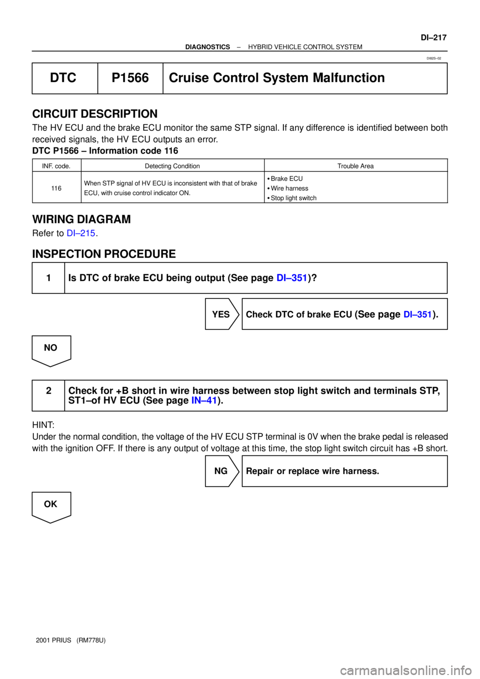
DTC P1566 Cruise Control System Malfunction
CIRCUIT DESCRIPTION
The HV ECU and the brake ECU monitor the same STP signal. If any difference is identified between both
received signals, the HV ECU outputs an error.
DTC P1566 ± Information code 116
INF. code.Detecting ConditionTrouble Area
11 6When STP signal of HV ECU is inconsistent with that of brake
ECU, with cruise control indicator ON.�Brake ECU
�Wire harness
�Stop light switch
WIRING DIAGRAM
Refer to DI±215.
INSPECTION PROCEDURE
1 Is DTC of brake ECU being output (See page DI±351)?
YES Check DTC of brake ECU (See page DI±351).
NO
2 Check for +B short in wire harness between stop light switch and terminals STP,
ST1±of HV ECU (See page IN±41).
HINT:
Under the normal condition, the voltage of the HV ECU STP terminal is 0V when the brake pedal is released
with the ignition OFF. If there is any output of voltage at this time, the stop light switch circuit has +B short.
NG Repair or replace wire harness.
OK
DI82S±02
Page 813 of 1943
DI±218
± DIAGNOSTICSHYBRID VEHICLE CONTROL SYSTEM
2001 PRIUS (RM778U)
3 Check for open and short in wire harness between stop light switch and brake
ECU.
NG Repair or replace wire harness.
OK
Check and replace stop light switch (See page BE±32).
Page 814 of 1943
A14146
BatteryB±G 1 1
F18 F13
Fusible Link
Block No. 2Hybrid Vehicle
Control ECU
H14
Engine Room J/B B
B J/C
1BFusible Link
Block No. 1
F12 B
1
MAIN 1F11
1 HV G±YJ2
J3G±Y
G±Y
IA143
BATT
± DIAGNOSTICSHYBRID VEHICLE CONTROL SYSTEM
DI±219
2001 PRIUS (RM778U)
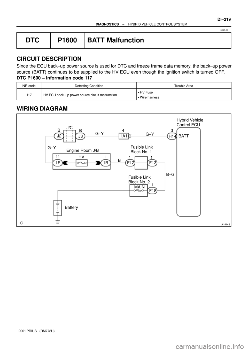
DTC P1600 BATT Malfunction
CIRCUIT DESCRIPTION
Since the ECU back±up power source is used for DTC and freeze frame data memory, the back±up power
source (BATT) continues to be supplied to the HV ECU even though the ignition switch is turned OFF.
DTC P1600 ± Information code 117
INF. code.Detecting ConditionTrouble Area
11 7HV ECU back±up power source circuit malfunction�HV Fuse
�Wire harness
WIRING DIAGRAM
DI82T±02
Page 815 of 1943
DI±220
± DIAGNOSTICSHYBRID VEHICLE CONTROL SYSTEM
2001 PRIUS (RM778U)
INSPECTION PROCEDURE
1 Check continuity of HV fuse of engine room J/B.
OK:
Continuity
NG Check for short in all harness and parts con-
nected to HV fuse.
OK
Repair or replace wire harness.
Page 816 of 1943

A14130
H13Hybrid Vehicle
Control ECU P1
Park/neutral Position SW
P
65
3 42
8VSFT
SFT
FSFT L±R
L±W
L±BN
D
B
R 14
11 1223 15
22 H13
H13
H13
H13
H13
H13
H1313
21 97LG±R
R±B
W
B
R
± DIAGNOSTICSHYBRID VEHICLE CONTROL SYSTEM
DI±221
2001 PRIUS (RM778U)
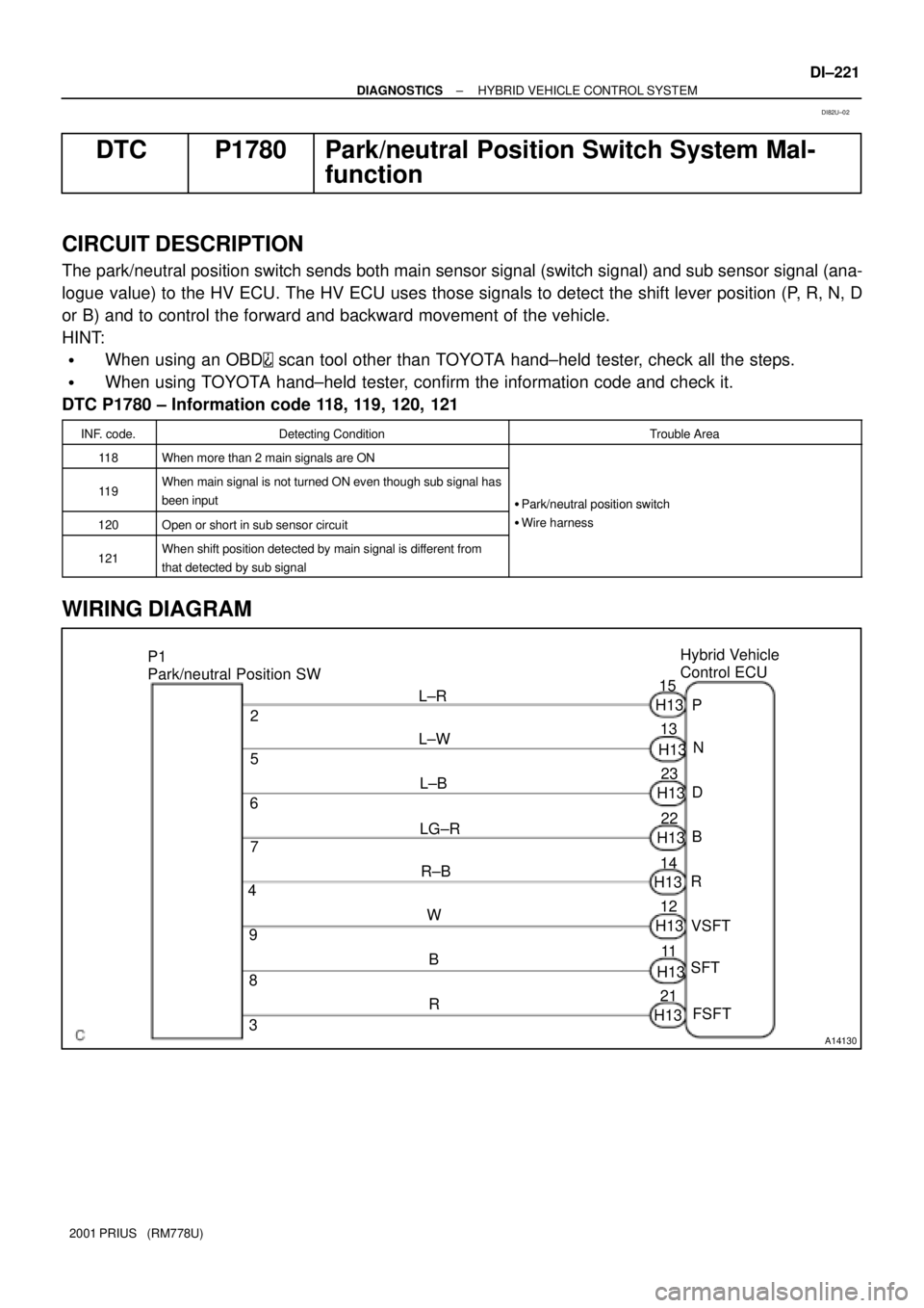
DTC P1780 Park/neutral Position Switch System Mal-
function
CIRCUIT DESCRIPTION
The park/neutral position switch sends both main sensor signal (switch signal) and sub sensor signal (ana-
logue value) to the HV ECU. The HV ECU uses those signals to detect the shift lever position (P, R, N, D
or B) and to control the forward and backward movement of the vehicle.
HINT:
�When using an OBD scan tool other than TOYOTA hand±held tester, check all the steps.
�When using TOYOTA hand±held tester, confirm the information code and check it.
DTC P1780 ± Information code 118, 119, 120, 121
INF. code.Detecting ConditionTrouble Area
11 8When more than 2 main signals are ON
11 9When main signal is not turned ON even though sub signal has
been input
�Park/neutral position switch
120Open or short in sub sensor circuit
�Park/neutral osition switch
�Wire harness
121When shift position detected by main signal is different from
that detected by sub signal
WIRING DIAGRAM
DI82U±02
Page 817 of 1943
DI±222
± DIAGNOSTICSHYBRID VEHICLE CONTROL SYSTEM
2001 PRIUS (RM778U)
INSPECTION PROCEDURE
1 Check for open and short in wire harness between park/neutral position switch
and HV ECU (See page IN±41).
Terminals for checking open and short:
Park/neutral Position Switch TerminalsHV ECU Terminals
2P
5N
6D
7B
4R
9VSFT
8SFT
3GSFT
NG Repair or replace wire harness.
OK
Check and repair park/neutral position switch (See page HT±54).
Page 818 of 1943
± DIAGNOSTICSHYBRID VEHICLE CONTROL SYSTEM
DI±225
2001 PRIUS (RM778U)
DTC P3004 Power Cable Malfunction
CIRCUIT DESCRIPTION
If the inverter voltage is not decreased after discharge with the ignition switch OFF, the VM sensor in the
inverter is determined as defective.
HINT:
�When using an OBD scan tool other than TOYOTA hand±held tester, check all the steps.
�When using TOYOTA hand±held tester, confirm the information code and check it.
DTC P3004 ± Information code 130
INF. Code.Detecting ConditionTrouble Area
130When HV battery voltage becomes lower than inverter voltageConverter & inverter assembly
INSPECTION PROCEDURE
1 Are there any other codes of HV ECU being outputs?
YES Go to relevant DTC chart.
NO
Replace converter & inverter assembly.
DI82X±02
Page 819 of 1943
DI±226
± DIAGNOSTICSHYBRID VEHICLE CONTROL SYSTEM
2001 PRIUS (RM778U)
DTC P3004 ± Information code 131
INF. Code.Detecting ConditionTrouble Area
131
When condition (a), (b) or (c) is detected:
(d) Main fuse blown out
(e) Service plug disconnected
(f) Limiter resistance cut off�Service plug
�Power cable
�System main relay
INSPECTION PROCEDURE
1 Is DTC of battery ECU being output?
YES Check the applicable DTC.
NO
2 Check condition of service plug terminal (Loosened, poor contact, etc.).
NG Replace service plug.
OK
3 Check continuity of power cable.
OK:
Continuity :Less than 1 W
NG Replace the power cable.
OK
Replace the system main relay.
Page 820 of 1943
A15179
BA
± DIAGNOSTICSHYBRID VEHICLE CONTROL SYSTEM
DI±227
2001 PRIUS (RM778U)
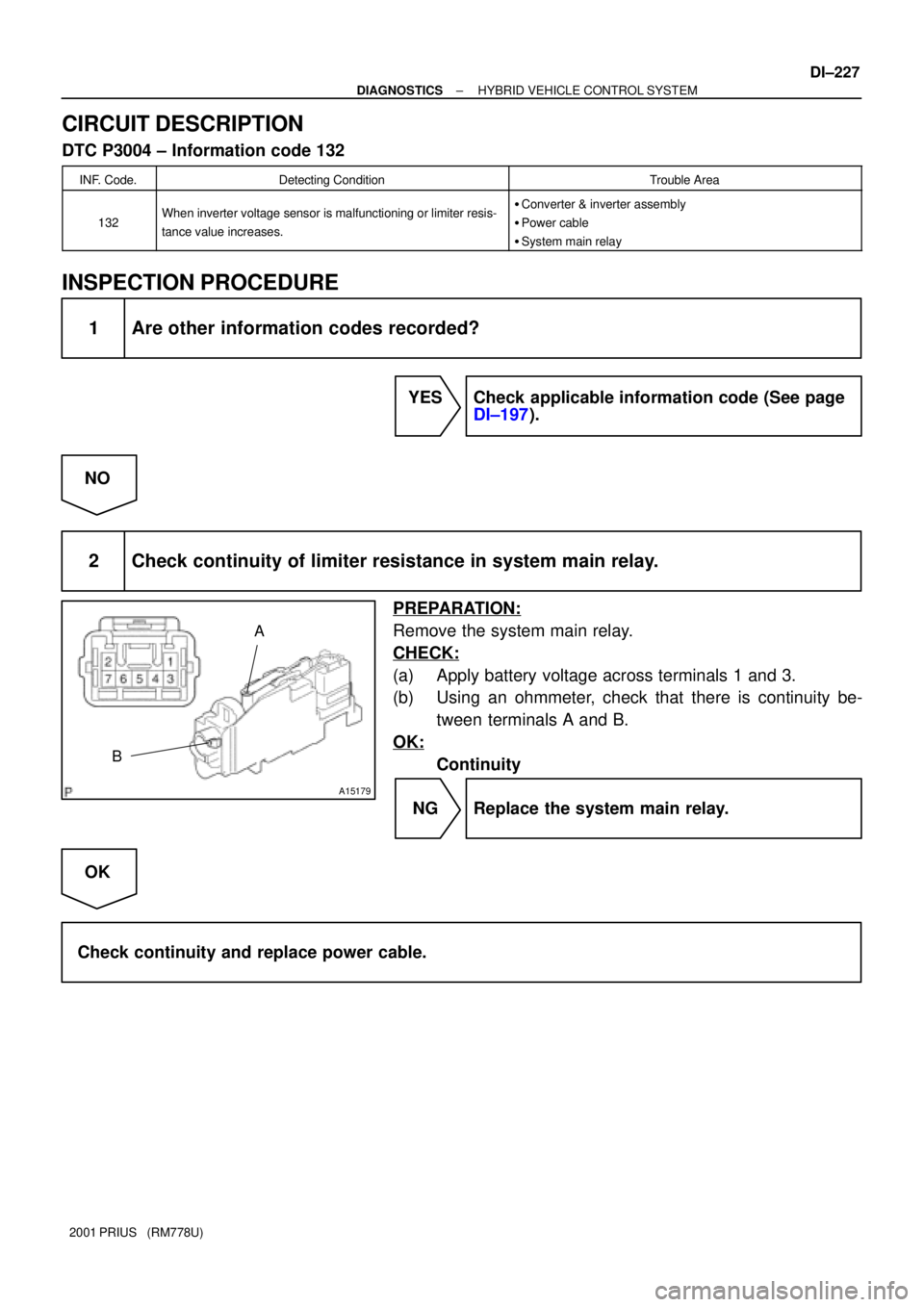
CIRCUIT DESCRIPTION
DTC P3004 ± Information code 132
INF. Code.Detecting ConditionTrouble Area
132When inverter voltage sensor is malfunctioning or limiter resis-
tance value increases.�Converter & inverter assembly
�Power cable
�System main relay
INSPECTION PROCEDURE
1 Are other information codes recorded?
YES Check applicable information code (See page
DI±197).
NO
2 Check continuity of limiter resistance in system main relay.
PREPARATION:
Remove the system main relay.
CHECK:
(a) Apply battery voltage across terminals 1 and 3.
(b) Using an ohmmeter, check that there is continuity be-
tween terminals A and B.
OK:
Continuity
NG Replace the system main relay.
OK
Check continuity and replace power cable.
Trending: light, traction control, run flat, fuel tank capacity, coolant capacity, washer fluid, key battery


