ESP TOYOTA PROACE VERSO 2022 Repair Manual
[x] Cancel search | Manufacturer: TOYOTA, Model Year: 2022, Model line: PROACE VERSO, Model: TOYOTA PROACE VERSO 2022Pages: 360, PDF Size: 70.79 MB
Page 178 of 360
178
NOTIC E
For more information on Speed limit recognition and memorising the speed limit in particular, refer to the corresponding section.
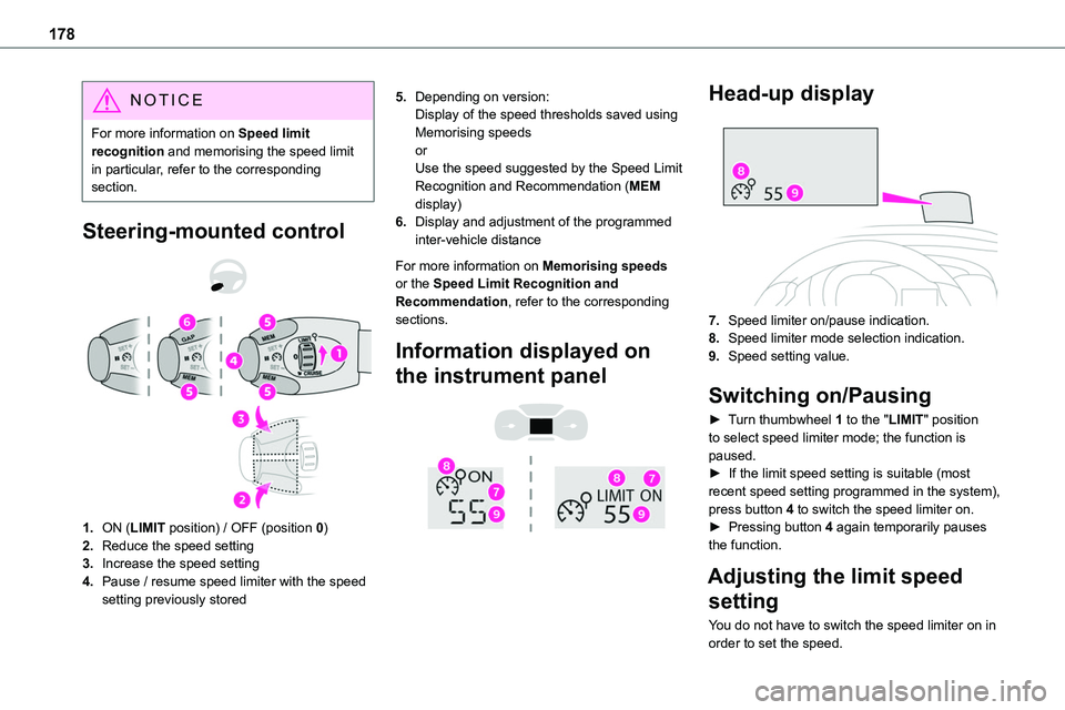
Steering-mounted control
1.ON (LIMIT position) / OFF (position 0)
2.Reduce the speed setting
3.Increase the speed setting
4.Pause / resume speed limiter with the speed setting previously stored
5.Depending on version:Display of the speed thresholds saved using Memorising speedsorUse the speed suggested by the Speed Limit Recognition and Recommendation (MEM display)
6.Display and adjustment of the programmed inter-vehicle distance
For more information on Memorising speeds or the Speed Limit Recognition and Recommendation, refer to the corresponding sections.
Information displayed on
the instrument panel
Head-up display
7.Speed limiter on/pause indication.
8.Speed limiter mode selection indication.
9.Speed setting value.
Switching on/Pausing
► Turn thumbwheel 1 to the "LIMIT" position to select speed limiter mode; the function is paused.► If the limit speed setting is suitable (most recent speed setting programmed in the system), press button 4 to switch the speed limiter on.► Pressing button 4 again temporarily pauses the function.
Adjusting the limit speed
setting
You do not have to switch the speed limiter on in order to set the speed.
Page 181 of 360
181
Driving
6
For more information on Memorising speeds or the Speed Limit Recognition and Recommendation, refer to the corresponding sections.
Information displayed on
the instrument panel
Head-up display
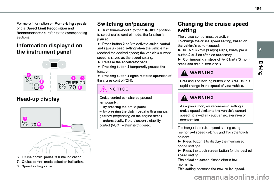
6.Cruise control pause/resume indication.
7.Cruise control mode selection indication.
8.Speed setting value.
Switching on/pausing
► Turn thumbwheel 1 to the "CRUISE" position to select cruise control mode; the function is paused.► Press button 2 or 3 to activate cruise control and save a speed setting when the vehicle has reached the desired speed; the vehicle’s current speed is saved as the speed setting.► Release the accelerator pedal.
► Pressing button 4 temporarily pauses the function.► Pressing button 4 again restores operation of the cruise control (ON).
NOTIC E
Cruise control can also be paused temporarily:– by pressing the brake pedal.– by pressing the clutch pedal with a manual gearbox (depending on the engine fitted).– automatically, if the electronic stability control (VSC) system is triggered.
Changing the cruise speed
setting
The cruise control must be active.To change the cruise speed setting, based on the vehicle’s current speed:► In +/- 1.6 km/h (1 mph) steps, briefly press button 2 or 3 as often as necessary.► Continuously, in steps of +/- 8 km/h (5 mph),
press and hold button 2 or 3.
WARNI NG
Pressing and holding button 2 or 3 results in a rapid change in the speed of your vehicle.
WARNI NG
As a precaution, we recommend setting a cruise speed similar to the vehicle’s current speed, to avoid any sudden acceleration or deceleration.
To change the cruise speed setting using memorised speed settings and from the touch screen:► Press button 5 to display the memorised speed settings.► Press the touch screen button for the desired speed setting.The selection screen closes after a few moments.
This setting becomes the new cruise speed.
Page 184 of 360
184
► Press 4 to restart cruise control. Cruise control may have been paused automatically:• When the inter-vehicle distance threshold is reached.• When the distance between your vehicle and the one in front becomes too short.• When the vehicle starts moving too slowly or the vehicle in front starts moving too slowly.• When the VSC system is triggered.
W ARNI NG
When the driver attempts to reactivate cruise control, after the function has been paused, the message "Activation not possible, unsuitable conditions" is briefly displayed if reactivation is not possible (safety conditions not met).
Using the Speed Limit Recognition and Recommendation function or speed limit sign memorisation to modify the speed setting.
► Press 5 to accept the speed setting proposed by the system on the instrument panel or touch screen, then press again to confirm.
WARNI NG
To prevent any sudden acceleration or deceleration of the vehicle, select a speed setting fairly close to the current speed of
your vehicle.
Changing the inter-vehicle distance
► Press 6 to display the distance setting thresholds ("Distant", "Normal" or "Close"), then press again to select a threshold.After a few seconds, the option is accepted and will be memorised when the ignition is switched off.
Temporarily exceeding the speed setting
► Depress the accelerator pedal. Distance monitoring and cruise control are deactivated as long as you continue to accelerate. The speed on the instrument panel flashes.
Deactivating the system
► Turn the knob 1 upwards into position 0 (OFF).
Information displayed on
the instrument panel
Head-up display
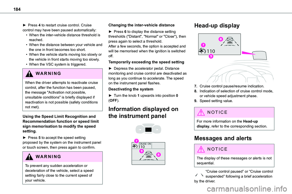
7.Cruise control pause/resume indication.
8.Indication of selection of cruise control mode, or vehicle speed adjustment phase.
9.Speed setting value.
NOTIC E
For more information on the Head-up display, refer to the corresponding section.
Messages and alerts
NOTIC E
The display of these messages or alerts is not
sequential.
“Cruise control paused” or “Cruise control suspended” following a brief acceleration by the driver.
Page 186 of 360
186
Malfunction
In the event of a malfunction with the adaptive cruise control, you will be alerted by an audible signal and the display of the message "Driving aid functions fault".Have it checked by any authorized Toyota retailer or Toyota authorized repairer, or any reliable repairer.
Active Safety Brake with
Collision Risk Alert and
Intelligent emergency
braking assistance
WARNI NG
Refer to the General recommendations on the use of driving and manoeuvring aids.
This system:– warns the driver that their vehicle is at risk of collision with the vehicle in front.– reduces the vehicle's speed to avoid a collision or limit its severity.This system is comprised of three functions:– Collision Risk Alert,
– Intelligent emergency braking assistance (iEBA).– Active Safety Brake (automatic emergency braking).
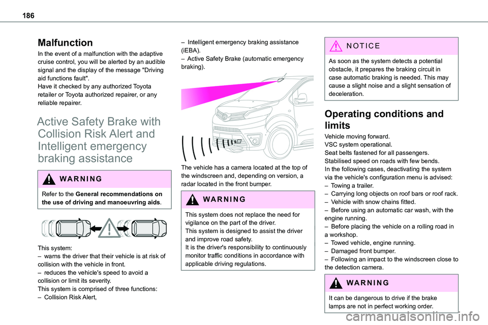
The vehicle has a camera located at the top of the windscreen and, depending on version, a radar located in the front bumper.
W ARNI NG
This system does not replace the need for vigilance on the part of the driver.This system is designed to assist the driver and improve road safety.It is the driver's responsibility to continuously monitor traffic conditions in accordance with applicable driving regulations.
NOTIC E
As soon as the system detects a potential obstacle, it prepares the braking circuit in case automatic braking is needed. This may cause a slight noise and a slight sensation of deceleration.
Operating conditions and
limits
Vehicle moving forward.VSC system operational.Seat belts fastened for all passengers.Stabilised speed on roads with few bends.In the following cases, deactivating the system via the vehicle's configuration menu is advised:– Towing a trailer.– Carrying long objects on roof bars or roof rack.– Vehicle with snow chains fitted.– Before using an automatic car wash, with the engine running.– Before placing the vehicle on a rolling road in a workshop.– Towed vehicle, engine running.– Damaged front bumper.– Following an impact to the windscreen close to the detection camera.
WARNI NG
It can be dangerous to drive if the brake lamps are not in perfect working order.
Page 189 of 360
189
Driving
6
Detection - Alert
You are alerted by the flashing of this warning lamp in the instrument panel, accompanied by an audible signal.
NOTIC E
No warning is transmitted while the direction indicator is active and for approximately 20 seconds after the direction indicator is switched off.
Activation/Deactivation
With audio system
► To activate or deactivate the system, press this button.The indicator lamp is on when the system is activated.
With touch screen
The settings are changed via the vehicle configuration menu.
Malfunction
Depending on the vehicle’s equipment:The indicator lamp in this button flashes.
or/The button flashes and a fault appears.Consult any authorized Toyota retailer or Toyota authorized repairer, or any reliable repairer.
NOTIC E
Detection may be impeded:– If the markings on the ground are worn and not clearly contrasted against the road surface.– If the windscreen is dirty.– In certain extreme weather conditions: fog, heavy rain, snow, shade, bright sunlight or direct exposure to the sun (e.g. low sun, leaving a tunnel).
Distraction detection
WARNI NG
Refer to the General recommendations on the use of driving and manoeuvring aids.
Depending on version, the function consists of either the "Coffee Break Alert" system alone or combined with the "Driver Attention Alert" system.
WARNI NG
These systems are in no way designed to keep the driver awake or to prevent the driver from falling asleep at the wheel. It is the driver’s responsibility to stop if feeling tired.Take a break in case of feeling tired or at least every 2 hours.
Activation/Deactivation
This function is set via the vehicle configuration menu.The state of the system is memorised when the ignition is switched off.
Page 194 of 360
194
Malfunction
In the event of a malfunction when changing into reverse gear, this warning lamp lights up on the instrument panel, accompanied by the display of a message and an audible signal (short beep).Have it checked by any authorized Toyota retailer or Toyota authorized repairer, or any reliable repairer.
VisioPark Light
WARNI NG
Refer to the General recommendations on the use of driving and manoeuvring aids.
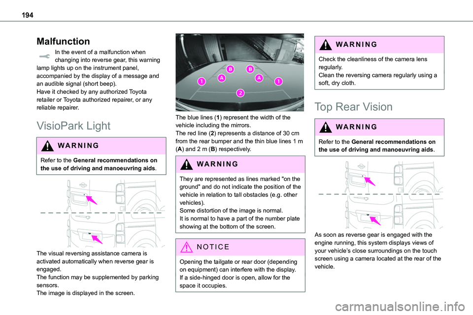
The visual reversing assistance camera is activated automatically when reverse gear is engaged.The function may be supplemented by parking sensors.The image is displayed in the screen.
The blue lines (1) represent the width of the vehicle including the mirrors.The red line (2) represents a distance of 30 cm from the rear bumper and the thin blue lines 1 m (A) and 2 m (B) respectively.
WARNI NG
They are represented as lines marked "on the ground" and do not indicate the position of the vehicle in relation to tall obstacles (e.g. other vehicles).Some distortion of the image is normal.It is normal to have a part of the number plate showing at the bottom of the screen.
NOTIC E
Opening the tailgate or rear door (depending on equipment) can interfere with the display.If a side-hinged door is open, allow for the space it occupies.
WARNI NG
Check the cleanliness of the camera lens regularly.Clean the reversing camera regularly using a soft, dry cloth.
Top Rear Vision
WARNI NG
Refer to the General recommendations on the use of driving and manoeuvring aids.
As soon as reverse gear is engaged with the engine running, this system displays views of your vehicle’s close surroundings on the touch screen using a camera located at the rear of the vehicle.
Page 196 of 360
196
NOTIC E
The function will be deactivated:– If a trailer is attached or a bicycle carrier is fitted on a towing device (vehicle fitted with a towing device installed in line with the manufacturer's recommendations).– Above about 6 mph (10 km/h).– When the boot is opened.
– Upon changing out of reverse gear (the image remains displayed for 7 seconds).– By pressing the white arrow in the upper-left corner of the touch screen.
AUTO mode
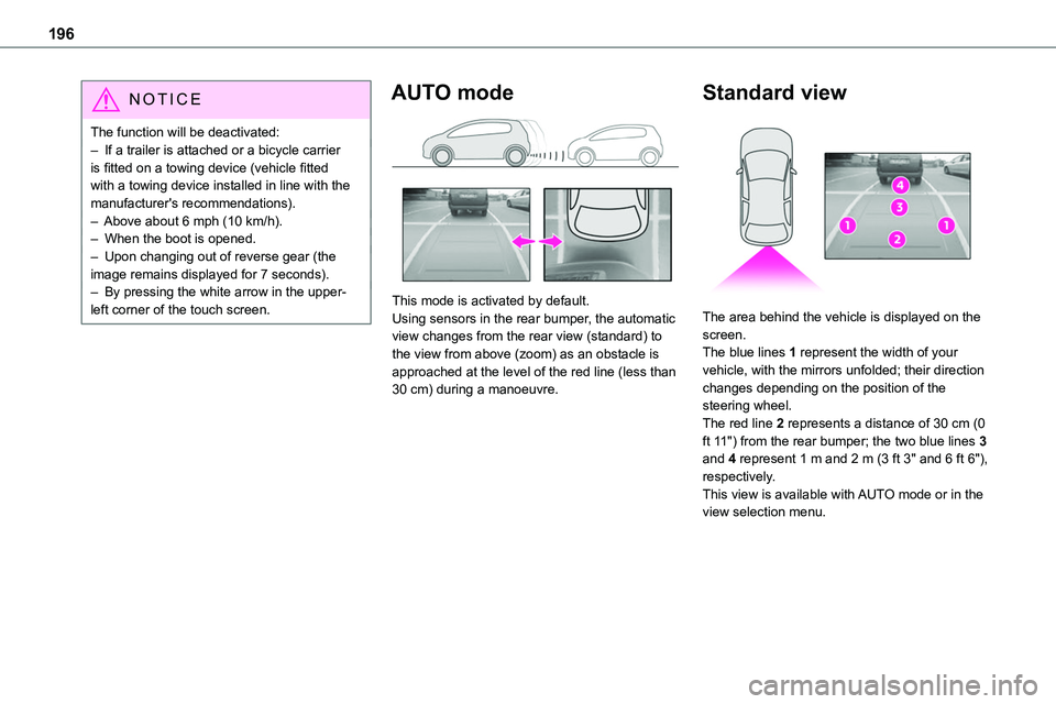
This mode is activated by default.Using sensors in the rear bumper, the automatic view changes from the rear view (standard) to the view from above (zoom) as an obstacle is approached at the level of the red line (less than 30 cm) during a manoeuvre.
Standard view
The area behind the vehicle is displayed on the screen.The blue lines 1 represent the width of your vehicle, with the mirrors unfolded; their direction changes depending on the position of the steering wheel.The red line 2 represents a distance of 30 cm (0 ft 11") from the rear bumper; the two blue lines 3 and 4 represent 1 m and 2 m (3 ft 3" and 6 ft 6"), respectively.This view is available with AUTO mode or in the view selection menu.
Page 198 of 360
198
Compatibility of fuels
Diesel fuels conforming to the EN590, EN16734 and EN16709 standards and containing up to 7%, 10%, 20% and 30% fatty acid methyl ester respectively. The use of B20 or B30 fuels, even occasionally, imposes special maintenance
conditions referred to as "Arduous conditions".
Paraffinic Diesel fuel conforming to the EN15940 standard.
WARNI NG
The use of any other type of (bio) fuel (vegetable or animal oils, pure or diluted, domestic fuel, etc.) is strictly prohibited (risk of damage to the engine and fuel system).
NOTIC E
The only Diesel fuel additives authorised for use are those that meet the B715000 standard.
Diesel at low temperature
At temperatures below 0 °C (+32 °F), the formation of paraffins in summer-type Diesel fuels could prevent the engine from operating correctly. In these temperature conditions, use winter-type Diesel fuel and keep the fuel tank more than 50 % full.At temperatures below -15 °C (+5 °F) to avoid problems starting, it is best to park the vehicle
under shelter (heated garage).
Travelling abroad
Certain fuels could damage your vehicle’s engine.In certain countries, the use of a particular fuel may be required (specific octane rating, specific trade name, etc.) to ensure correct operation of the engine.For all additional information, consult a dealer.
Refuelling
Fuel tank capacity: approximately 69 litres.Reserve level: approximately 6 litres.
Low fuel level
When the low fuel level is reached, one of these warning lamps lights up on the instrument panel, accompanied by the
display of a message and an audible signal. When it first comes on, about 8 litres of fuel remain.You must refuel as soon as possible to avoid running out of fuel.For more information on Running out of fuel (Diesel), refer to the corresponding section.
NOTIC E
A small arrow by the warning lamp indicates which side of the vehicle the fuel filler flap is located on.
WARNI NG
Stop & StartNever refuel with the engine in STOP mode; you must switch off the ignition.
Page 208 of 360
208
Charging the traction
battery (Electric)
To recharge, connect the vehicle to a domestic electricity supply (domestic or accelerated charging) or to a fast public charger (superfast charging).For a full charge, follow the desired charging procedure without pausing it, until it ends
automatically. Charging can be either immediate or deferred (except fast public charger, mode 4).You can stop domestic or accelerated charging at any time by unlocking the vehicle and removing the nozzle. For superfast charging, refer to the fast public charger.For more information on the charging displays on the Instrument panel and the Touch screen, refer to the corresponding section.
NOTIC E
It is also possible to monitor the charging progress using the MyToyota application (Available soon).For more information on Remote functions, refer to the corresponding section.
NOTIC E
Lounge modeWhen the vehicle is connected, it is possible to switch on the ignition and use certain functions such as the audio and telematics system and the air conditioning system for several hours.
WARNI NG
As a safety measure, the engine will not start if the charging cable is plugged into the connector on the vehicle. A warning is displayed on the instrument panel.
NOTIC E
Cooling the traction batteryThe cooling fan in the engine compartment comes on during charging to cool the on-board charger and the traction battery.
NOTIC E
Vehicle immobilised for 1 to 12 monthsDischarge the traction battery down to 2 or 3 bars on the charge level indicator on the instrument panel.Do not connect the charging cable.
Always park the vehicle in a place with temperatures between -10°C and 30°C (parking in a place with extreme temperatures can damage the traction battery).Disconnect the cable from the (+) terminal of the accessory battery in the engine compartment.Connect a 12 V battery charger to the (+) and (-) terminals of the accessory battery about
every 3 months in order to recharge the accessory battery and maintain an operating voltage.
Precautions
Electric vehicles were developed in accordance with the guidelines on maximum electromagnetic fields issued by the International Commission on Non-Ionizing Radiation Protection (ICNIRP - 1998 Guidelines).
Wearers of pacemakers or equivalent devices
The electric vehicles have been developed in accordance with the guidelines on the maximum levels for electromagnetic fields issued by the International Commission on Non-Ionizing Radiation Protection (ICNIRP - 1998 Guidelines).
Page 210 of 360
210
► Connect the charging cable from the control unit to the domestic socket.When the connection is made, all of the indicator lamps on the control unit light up, then only the POWER indicator lamp remains on in green.► Remove the protective cover from the charging nozzle.► Insert the nozzle into the charging connector.The start of charging is confirmed by the flashing
green CHARGE indicator lamps in the flap, then those on the control unit.If this is not the case, charging has not started; restart the procedure, ensuring that all connections are properly established.The red indicator lamp in the flap comes on to indicate that the nozzle is locked.
NOTIC E
When charging is complete and while the charging cable is still connected, opening the driver's door will display the charge level on the instrument panel for about 20 seconds.
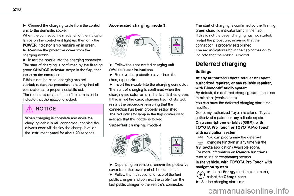
Accelerated charging, mode 3
► Follow the accelerated charging unit (Wallbox) user instructions.► Remove the protective cover from the charging nozzle.► Insert the nozzle into the charging connector.The start of charging is confirmed when the charging indicator lamp in the flap flashes green.If this is not the case, charging has not started; restart the procedure, ensuring that the connection has been properly established.The red indicator lamp in the flap comes on to indicate that the nozzle is locked.
Superfast charging, mode 4
► Depending on version, remove the protective cover from the lower part of the connector.► Follow the instructions for use of the fast public charger and connect the cable from the fast public charger to the vehicle's connector.
The start of charging is confirmed by the flashing green charging indicator lamp in the flap.If this is not the case, charging has not started; restart the procedure, ensuring that the connection is properly established.The red indicator lamp in the flap comes on to indicate that the nozzle is locked.
Deferred charging
Settings
At any authorized Toyota retailer or Toyota authorized repairer, or any reliable repairer, with Bluetooth® audio systemBy default, the deferred charging start time is set to midnight (vehicle time).You can have the deferred charging start time modified.Go to any authorized Toyota retailer or Toyota authorized repairer, or any reliable repairer.On a smartphone or tablet (GSM), with TOYOTA Pro Touch or TOYOTA Pro Touch with navigation systemYou can programme the deferred charging function at any time via the MyToyota application (Available soon).For more information on Remote functions, refer to the corresponding section.In the vehicle, with TOYOTA Pro Touch with navigation system► In the Energy touch screen menu, select the Charge page.► Set the charging start time.