ESP TOYOTA PROACE VERSO 2022 Manual Online
[x] Cancel search | Manufacturer: TOYOTA, Model Year: 2022, Model line: PROACE VERSO, Model: TOYOTA PROACE VERSO 2022Pages: 360, PDF Size: 70.79 MB
Page 232 of 360
232
NOTIC E
Tyre inflation pressures are indicated on this label.For more information on Identification markings, particularly this label, refer to the corresponding section.
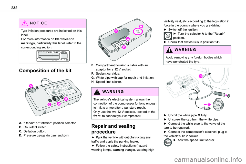
Composition of the kit
A."Repair" or "Inflation" position selector.
B.On I/off O switch.
C.Deflation button.
D.Pressure gauge (in bars and psi).
E.Compartment housing a cable with an adaptor for a 12 V socket.
F.Sealant cartridge.
G.White pipe with cap for repair and inflation.
H.Speed limit sticker.
WARNI NG
The vehicle's electrical system allows the connection of the compressor for long enough to inflate a tyre after a puncture repair.
Only use the two 12 V sockets, located at the front, to connect your compressor.
Repair and sealing
procedure
► Park the vehicle without obstructing any traffic and apply the parking brake.► Follow the safety instructions (hazard warning lamps, warning triangle, wearing high
visibility vest, etc.) according to the legislation in force in the country where you are driving.► Switch off the ignition.► Turn the selector A to the "Repair" position.► Check that switch B is in position "O".
WARNI NG
Avoid removing any foreign bodies which have penetrated the tyre.
► Uncoil the white pipe G fully.► Unscrew the cap from the white pipe.► Connect the white pipe to the valve of the tyre to be repaired.► Connect the compressor's electrical plug to the vehicle's 12 V socket.► Affix the speed limit sticker.
Page 234 of 360
234
WARNI NG
Go to any authorized Toyota retailer or Toyota authorized repairer, or any reliable repairer as soon as possible.You must tell the technician that the kit has been used. After inspection, the technician will advise you on whether the tyre can be repaired or if it must be replaced.
► Adjust the tyre pressure using the compressor (to inflate: set switch B to position "I"; to deflate: set switch B to position "O" and press button C), according to the vehicle's tyre pressure label located by the driver's door.A subsequent loss of pressure indicates that the puncture has not been fully sealed; contact any authorized Toyota retailer or Toyota authorized repairer, or any reliable repairer to have your vehicle repaired.► Remove the kit and stow it.► Drive at reduced speed (50 mph (80 km/h) max.), limiting the distance travelled to approximately 125 miles (200 km).
NOTIC E
The compressor can also be used, without injecting sealant, to check and adjust the tyre pressures.
NOTIC E
If after approximately 7 minutes the required pressure is not reached, this indicates that the tyre is irreparably damaged; contact any authorized Toyota retailer or Toyota authorized repairer, or any reliable repairer for assistance.
WARNI NG
Do not drive more than 125 miles (200 km) with a repaired tyre; see any authorized Toyota retailer or Toyota authorized repairer, or any reliable repairer to have the tyre changed.
WARNI NG
Should the pressure of one or more tyres be adjusted, it is necessary to reinitialise the under-inflation detection system.For more information on Tyre under-inflation detection, refer to the corresponding section.
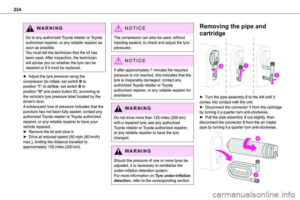
Removing the pipe and
cartridge
► Turn the pipe assembly 2 to the left until it comes into contact with the unit.► Disconnect the connector 1 from the cartridge by turning it a quarter turn anti-clockwise.► Pull the pipe assembly 2 out slightly, then disconnect the connector 3 from the air intake pipe by turning it a quarter turn anti-clockwise.
Page 235 of 360
235
In the event of a breakdown
8
► Remove the pipe assembly 2.► Hold the compressor up vertically.► Unscrew the cartridge 4 from the bottom.To fit the new cartridge and new pipe, carry out these operations in reverse order.
WARNI NG
Beware of fluid discharge.The expiry date of the fluid is indicated on the cartridge.The sealant cartridge is designed for single use; it must be replaced even if only partly used.After use, do not discard the cartridge in standard waste, take it to any authorized Toyota retailer or Toyota authorized repairer, or any reliable repairer waste disposal site.Do not forget to obtain a new cartridge, available from any authorized Toyota retailer or Toyota authorized repairer, or any reliable repairer.
Spare wheel
Access to the tools
The tools are stowed in a tool box.
NOTIC E
For more information on the Tool box, refer to the corresponding section.
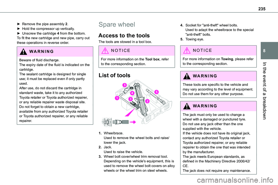
List of tools
1.Wheelbrace.Used to remove the wheel bolts and raise/lower the jack.
2.Jack.Used to raise the vehicle.
3.Wheel bolt cover/wheel trim removal tool.Depending on the vehicle's equipment, this is used to remove the wheel bolt covers on alloy wheels or the wheel trim on steel wheels.
4.Socket for "anti-theft" wheel bolts.Used to adapt the wheelbrace to the special "anti-theft" bolts.
5.Towing eye.
NOTIC E
For more information on Towing, please refer to the corresponding section.
WARNI NG
These tools are specific to the vehicle and may vary according to the level of equipment.Do not use them for any other purpose.
WARNI NG
The jack must only be used to change a wheel with a damaged or punctured tyre.Do not use any jack other than the one supplied with the vehicle.If the vehicle does not have its original jack, contact any authorized Toyota retailer or Toyota authorized repairer, or any reliable repairer to obtain the one that was intended by the manufacturer.
The jack meets European standards, as defined in the Machinery Directive 2006/42/CE.The jack does not require any maintenance.
Page 236 of 360
236
Access to the spare wheel
► Access to the spare wheel is from the rear.► Depending on version, open the side-hinged doors or the tailgate.
NOTIC E
To avoid any unwanted opening of the electric side door(s), deactivate the Hands-Free Access function in the vehicle configuration menu.For more information on the Hands-Free Sliding Side Door, refer to the corresponding section.
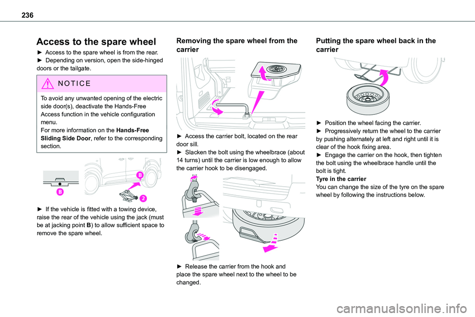
► If the vehicle is fitted with a towing device,
raise the rear of the vehicle using the jack (must be at jacking point B) to allow sufficient space to remove the spare wheel.
Removing the spare wheel from the
carrier
► Access the carrier bolt, located on the rear door sill.► Slacken the bolt using the wheelbrace (about 14 turns) until the carrier is low enough to allow the carrier hook to be disengaged.
► Release the carrier from the hook and place the spare wheel next to the wheel to be changed.
Putting the spare wheel back in the
carrier
► Position the wheel facing the carrier.► Progressively return the wheel to the carrier by pushing alternately at left and right until it is clear of the hook fixing area.► Engage the carrier on the hook, then tighten the bolt using the wheelbrace handle until the bolt is tight.Tyre in the carrierYou can change the size of the tyre on the spare wheel by following the instructions below.
Page 239 of 360
239
In the event of a breakdown
8
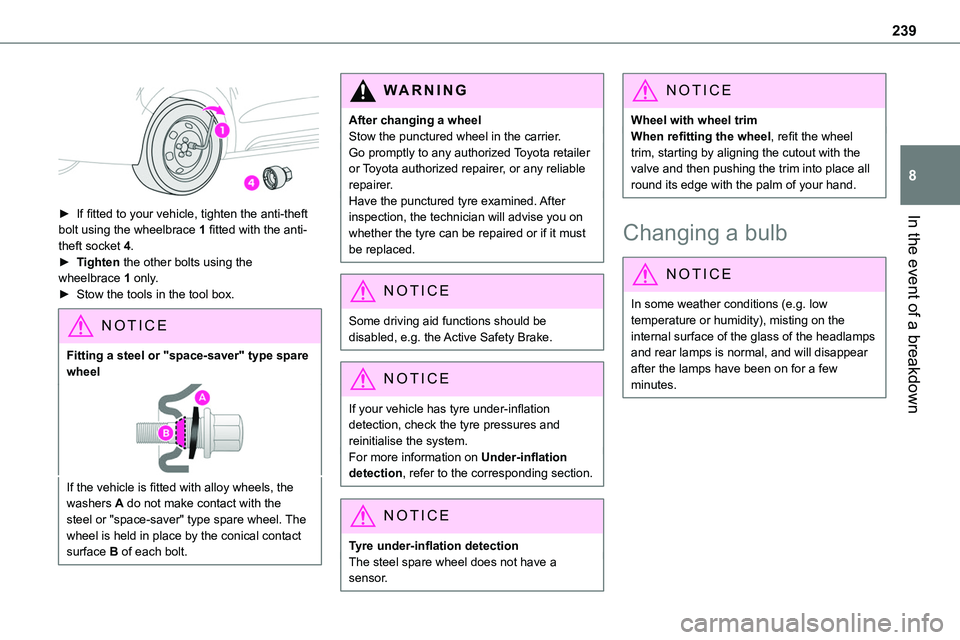
► If fitted to your vehicle, tighten the anti-theft
bolt using the wheelbrace 1 fitted with the anti-theft socket 4.► Tighten the other bolts using the wheelbrace 1 only.► Stow the tools in the tool box.
NOTIC E
Fitting a steel or "space-saver" type spare wheel
If the vehicle is fitted with alloy wheels, the washers A do not make contact with the steel or "space-saver" type spare wheel. The wheel is held in place by the conical contact surface B of each bolt.
WARNI NG
After changing a wheelStow the punctured wheel in the carrier.Go promptly to any authorized Toyota retailer or Toyota authorized repairer, or any reliable repairer.Have the punctured tyre examined. After inspection, the technician will advise you on
whether the tyre can be repaired or if it must be replaced.
NOTIC E
Some driving aid functions should be disabled, e.g. the Active Safety Brake.
NOTIC E
If your vehicle has tyre under-inflation detection, check the tyre pressures and reinitialise the system.For more information on Under-inflation detection, refer to the corresponding section.
NOTIC E
Tyre under-inflation detectionThe steel spare wheel does not have a sensor.
NOTIC E
Wheel with wheel trimWhen refitting the wheel, refit the wheel trim, starting by aligning the cutout with the valve and then pushing the trim into place all round its edge with the palm of your hand.
Changing a bulb
NOTIC E
In some weather conditions (e.g. low temperature or humidity), misting on the internal surface of the glass of the headlamps and rear lamps is normal, and will disappear after the lamps have been on for a few minutes.
Page 241 of 360
241
In the event of a breakdown
8
WARNI NG
Be aware of the zone behind the right lamp (vehicle direction), which may be hot with a risk of burning (degassing hoses).
Accessing the bulbs
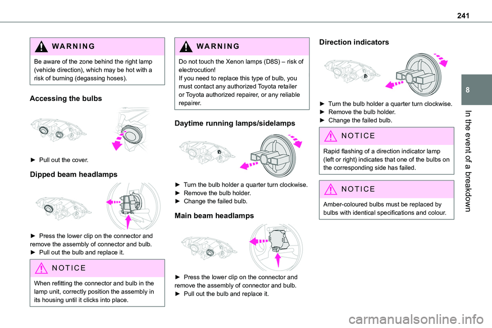
► Pull out the cover.
Dipped beam headlamps
► Press the lower clip on the connector and remove the assembly of connector and bulb.► Pull out the bulb and replace it.
NOTIC E
When refitting the connector and bulb in the lamp unit, correctly position the assembly in
its housing until it clicks into place.
WARNI NG
Do not touch the Xenon lamps (D8S) – risk of electrocution!If you need to replace this type of bulb, you must contact any authorized Toyota retailer or Toyota authorized repairer, or any reliable repairer.
Daytime running lamps/sidelamps
► Turn the bulb holder a quarter turn clockwise.► Remove the bulb holder.► Change the failed bulb.
Main beam headlamps
► Press the lower clip on the connector and remove the assembly of connector and bulb. ► Pull out the bulb and replace it.
Direction indicators
► Turn the bulb holder a quarter turn clockwise.► Remove the bulb holder.
► Change the failed bulb.
NOTIC E
Rapid flashing of a direction indicator lamp (left or right) indicates that one of the bulbs on the corresponding side has failed.
NOTIC E
Amber-coloured bulbs must be replaced by bulbs with identical specifications and colour.
Page 245 of 360
245
In the event of a breakdown
8
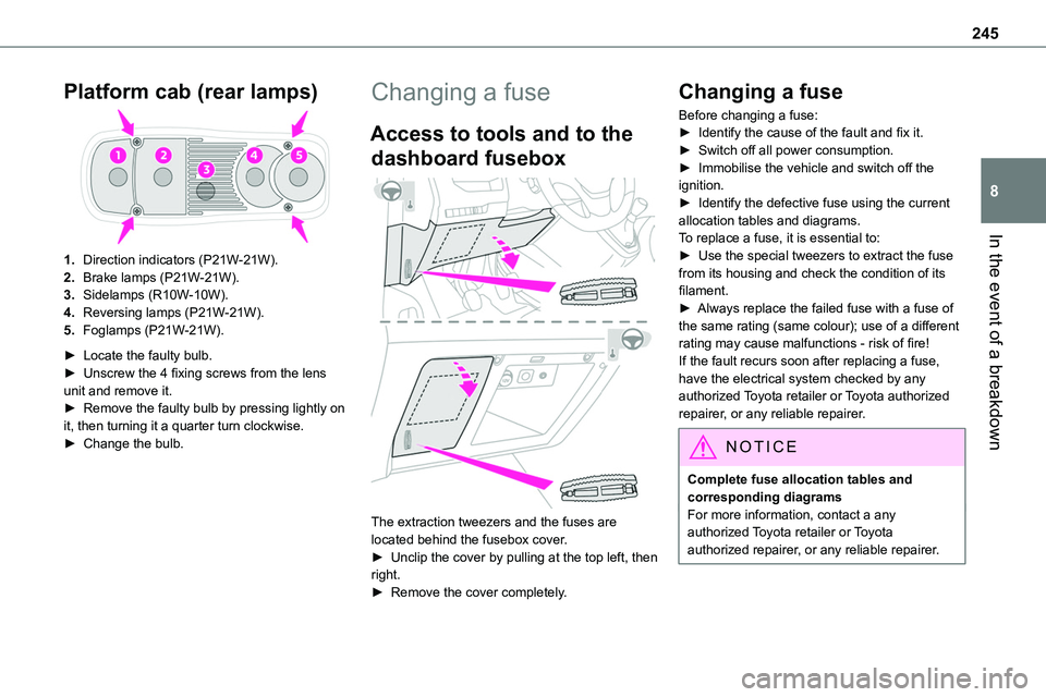
Platform cab (rear lamps)
1.Direction indicators (P21W-21W).
2.Brake lamps (P21W-21W).
3.Sidelamps (R10W-10W).
4.Reversing lamps (P21W-21W).
5.Foglamps (P21W-21W).
► Locate the faulty bulb.► Unscrew the 4 fixing screws from the lens unit and remove it.► Remove the faulty bulb by pressing lightly on it, then turning it a quarter turn clockwise.► Change the bulb.
Changing a fuse
Access to tools and to the
dashboard fusebox
The extraction tweezers and the fuses are located behind the fusebox cover.► Unclip the cover by pulling at the top left, then right.
► Remove the cover completely.
Changing a fuse
Before changing a fuse:► Identify the cause of the fault and fix it.► Switch off all power consumption.► Immobilise the vehicle and switch off the ignition.► Identify the defective fuse using the current allocation tables and diagrams.To replace a fuse, it is essential to:
► Use the special tweezers to extract the fuse from its housing and check the condition of its filament.► Always replace the failed fuse with a fuse of the same rating (same colour); use of a different rating may cause malfunctions - risk of fire!If the fault recurs soon after replacing a fuse, have the electrical system checked by any authorized Toyota retailer or Toyota authorized repairer, or any reliable repairer.
NOTIC E
Complete fuse allocation tables and corresponding diagramsFor more information, contact a any authorized Toyota retailer or Toyota authorized repairer, or any reliable repairer.
Page 246 of 360
246
WARNI NG
The replacement of a fuse not shown in the allocation tables could cause a serious malfunction of the vehicle.Consult any authorized Toyota retailer or Toyota authorized repairer, or any reliable repairer.
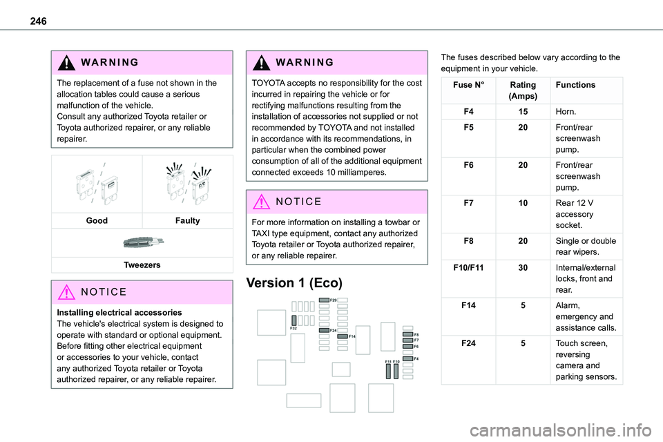
GoodFaulty
Tweezers
NOTIC E
Installing electrical accessoriesThe vehicle's electrical system is designed to operate with standard or optional equipment.Before fitting other electrical equipment or accessories to your vehicle, contact
any authorized Toyota retailer or Toyota authorized repairer, or any reliable repairer.
WARNI NG
TOYOTA accepts no responsibility for the cost incurred in repairing the vehicle or for rectifying malfunctions resulting from the installation of accessories not supplied or not recommended by TOYOTA and not installed in accordance with its recommendations, in particular when the combined power
consumption of all of the additional equipment connected exceeds 10 milliamperes.
NOTIC E
For more information on installing a towbar or TAXI type equipment, contact any authorized Toyota retailer or Toyota authorized repairer, or any reliable repairer.
Version 1 (Eco)
The fuses described below vary according to the equipment in your vehicle.
Fuse N°Rating(Amps)Functions
F415Horn.
F520Front/rear screenwash pump.
F620Front/rear screenwash pump.
F710Rear 12 V accessory socket.
F820Single or double rear wipers.
F10/F1130Internal/external locks, front and rear.
F145Alarm, emergency and assistance calls.
F245Touch screen, reversing camera and parking sensors.
Page 248 of 360
248
Fuse N°Rating(Amps)Functions
F2215Horn.
F2315Right-hand main beam headlamp.
F2415Left-hand
main beam headlamp.
12 V battery / Accessory
battery
Procedure for starting the engine using another battery or charging a discharged battery.
Lead-acid starter batteries
ECO
Batteries contain harmful substances such as sulphuric acid and lead.They must be disposed of in accordance with regulations and must not, in any circumstances, be discarded with household waste.Take used remote control batteries and vehicle batteries to a special collection point.
WARNI NG
Protect your eyes and face before handling the battery.All operations on the battery must be carried out in a well ventilated area and away from naked flames and sources of sparks, so as to avoid the risk of explosion or fire.Wash your hands afterwards.
Electric motor
NOTIC E
Flat accessory batteryIt is no longer possible to start the motor or recharge the traction battery.
WARNI NG
Precautions before working on the accessory batterySelect mode P, switch off the ignition, check that the instrument panel is off and that the vehicle is not plugged in.
WARNI NG
Jump-starting another vehicleDo not use the accessory battery to jump-start another vehicle or to charge another vehicle's battery.
WARNI NG
Always replace the battery with one of equivalent specification.
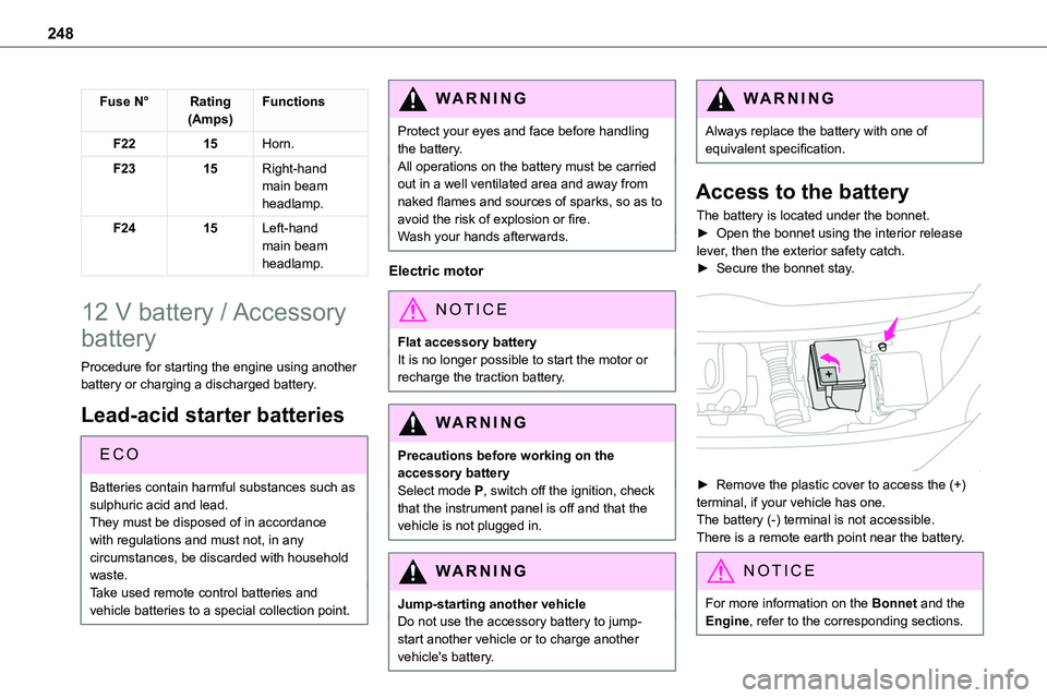
Access to the battery
The battery is located under the bonnet.► Open the bonnet using the interior release
lever, then the exterior safety catch.► Secure the bonnet stay.
► Remove the plastic cover to access the (+) terminal, if your vehicle has one.The battery (-) terminal is not accessible.There is a remote earth point near the battery.
NOTIC E
For more information on the Bonnet and the Engine, refer to the corresponding sections.
Page 252 of 360
252
Towing
Procedure for having your vehicle towed or for towing another vehicle using a removable mechanical device.
NOTIC E
General recommendationsObserve the legislation in force in the country
where you are driving.Ensure that the weight of the towing vehicle is higher than that of the towed vehicle.The driver must remain at the wheel of the towed vehicle and must have a valid driving licence.When towing a vehicle with all four wheels on the ground, always use an approved towbar; ropes and straps are prohibited.The towing vehicle must move off gently.When the vehicle is towed with its engine off, there is no longer braking and steering assistance.
WARNI NG
A professional recovery service must be called if:– broken down on a motorway or main road;– not possible to put the gearbox into neutral, unlock the steering, or release the parking brake;– not possible to tow a vehicle with an
automatic gearbox, with the engine running;– towing with only two wheels on the ground;– four-wheel drive vehicle;– no approved towbar available.
WARNI NG
Before towing the vehicle, it is essential to put the vehicle in free-wheeling mode.For more information on Free-wheeling, refer to the corresponding section.
NOTIC E
Electric motorAn electric vehicle cannot under any circumstances be used to tow another vehicle.However, it may be used, for example, to exit a rut.
WARNI NG
With a manual gearbox, place the gear lever in neutral.With an automatic gearbox, place the gear selector in position N.Failure to adhere to this instruction may lead to damage to some braking components and the lack of braking assistance on restarting the engine.