fuse TOYOTA RAV4 1996 Service User Guide
[x] Cancel search | Manufacturer: TOYOTA, Model Year: 1996, Model line: RAV4, Model: TOYOTA RAV4 1996Pages: 1632, PDF Size: 41.64 MB
Page 88 of 1632
Fig. 15: Releasing Shorting Spring
Courtesy of TOYOTA MOTOR SALES, U.S.A., INC.
DIAGNOSTIC TESTS
AIR BAG WARNING LIGHT DOES NOT ILLUMINATE
Description
AIR BAG warning light is located in instrument cluster. When air bag system is normal, AIR BAG warning
light illuminates for about 6 seconds after ignition switch is turned from LOCK to ACC or ON position, and
turns off automatically. If a malfunction is present in air bag system, AIR BAG warning light illuminates to
inform operator of malfunction. When Data Link Connector 1 (DLC1) terminals Tc and E1 are connected
together, a Diagnostic Trouble Code (DTC) is displayed by flashing AIR BAG warning light.
Diagnostic Procedure
1. Remove SRS-B fuse and check continuity across fuse blades. SRS-B fuse is located in instrument panel
fuse block under left side of instrument panel. If fuse is faulty, go to step 4). If fuse is okay, reinstall fuse
and go to next step.
2. Disable air bag system. See DISABLING SYSTEM
under DISABLING & ACTIVATING AIR BAG
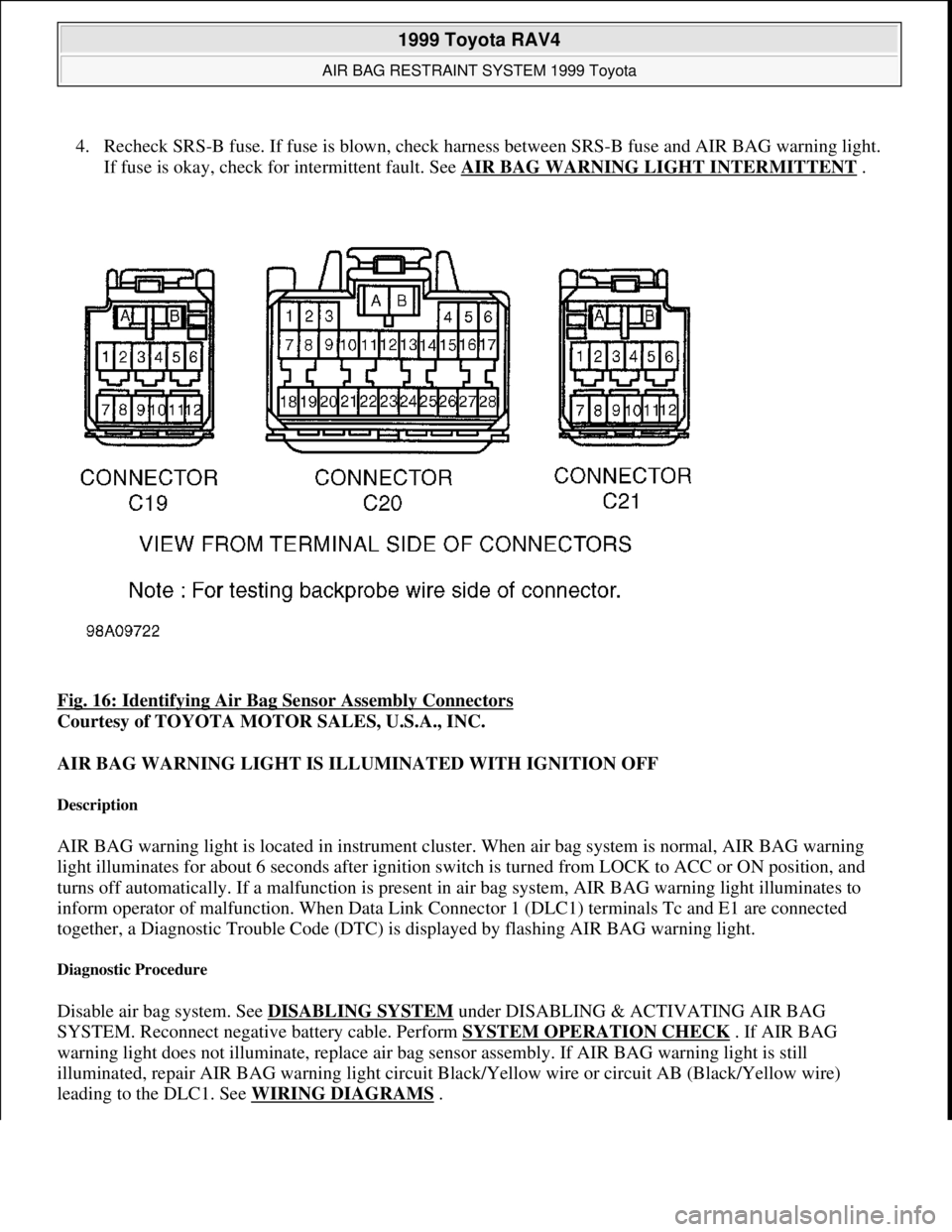
SYSTEM. Reconnect negative battery cable. Turn ignition switch to ACC or ON position. Measure
voltage between ground and harness side of air bag sensor assembly connector C20, terminal No. 3
(circuit LA, Black/Yellow wire). See Fig. 16
. If 10-14 volts is not present, repair AIR BAG warning
light bulb or circuit. If 10-14 volts is present, go to next step.
3. Turn ignition switch to LOCK position. Disconnect negative battery cable. Reconnect 3 air bag sensor
assembly connectors. Leave air bag modules, pretensioners and front air bag sensors disconnected.
Reconnect negative battery cable and wait at least 2 seconds. Turn ignition switch to ACC or ON
position. If AIR BAG warning light illuminates, system operation is normal. If AIR BAG warning light
does not come on, check for poor connection at air bag sensor assembly connector C20, terminal No. 3
(Black/Yellow wire). If connection is oka
y, replace air bag sensor assembly. WARNING:Failure to follow service precautions may result in air bag deployment and
personal injury. See SERVICE PRECAUTIONS
. After component
replacement, check system operation. See SYSTEM OPERATION CHECK
.
CAUTION: Ensure ignition switch is in LOCK position before disconnecting or
connecting negative battery cable. If ignition switch is in ACC or ON
position when negative battery cable is disconnected or connected, air
bag sensor may be damaged. To prevent damage to connector terminals,
DO NOT probe terminal ends. Instead, backprobe terminals (probe
terminal where wire enters harness connector).
NOTE: In the following tests, the term squib connector and module connector may be
used interchangeably.
1999 Toyota RAV4
AIR BAG RESTRAINT SYSTEM 1999 Toyota
Microsoft
Sunday, November 22, 2009 10:33:23 AMPage 25 © 2005 Mitchell Repair Information Company, LLC.
Page 89 of 1632
4. Recheck SRS-B fuse. If fuse is blown, check harness between SRS-B fuse and AIR BAG warning light.
If fuse is okay, check for intermittent fault. See AIR BAG WARNING LIGHT INTERMITTENT
.
Fig. 16: Identifying Air Bag Sensor Assembly Connectors
Courtesy of TOYOTA MOTOR SALES, U.S.A., INC.
AIR BAG WARNING LIGHT IS ILLUMINATED WITH IGNITION OFF
Description
AIR BAG warning light is located in instrument cluster. When air bag system is normal, AIR BAG warning
light illuminates for about 6 seconds after ignition switch is turned from LOCK to ACC or ON position, and
turns off automatically. If a malfunction is present in air bag system, AIR BAG warning light illuminates to
inform operator of malfunction. When Data Link Connector 1 (DLC1) terminals Tc and E1 are connected
together, a Diagnostic Trouble Code (DTC) is displayed by flashing AIR BAG warning light.
Diagnostic Procedure
Disable air bag system. See DISABLING SYSTEM under DISABLING & ACTIVATING AIR BAG
SYSTEM. Reconnect negative battery cable. Perform SYSTEM OPERATION CHECK
. If AIR BAG
warning light does not illuminate, replace air bag sensor assembly. If AIR BAG warning light is still
illuminated, repair AIR BAG warning light circuit Black/Yellow wire or circuit AB (Black/Yellow wire)
leadin
g to the DLC1. See WIRING DIAGRAMS.
1999 Toyota RAV4
AIR BAG RESTRAINT SYSTEM 1999 Toyota
Microsoft
Sunday, November 22, 2009 10:33:23 AMPage 26 © 2005 Mitchell Repair Information Company, LLC.
Page 405 of 1632
Check all fuses, fusible links, ignition switch and appropriate relays (if equipped). Check generator output. See
NO
-LOAD TEST under ON-VEHICLE TESTING.
ON-VEHICLE TESTING
NO-LOAD TEST
1. Disconnect battery-to-generator terminal "B" wire. See Fig. 2
. Using an ammeter and voltmeter, connect
negative ammeter lead to disconnected generator terminal "B" wire end, and connect positive ammeter
lead to generator terminal "B".
2. Connect voltmeter positive lead to generator terminal "B" and negative lead to ground. See Fig. 2
. Start
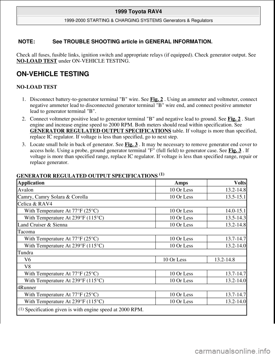
engine and increase engine speed to 2000 RPM. Both meters should read within specification. See
GENERATOR REGULATED OUTPUT SPECIFICATIONS
table. If voltage is more than specified,
replace IC regulator. If voltage is less than specified, go to next step.
3. Locate small hole in back of generator. See Fig. 3
. It may be necessary to remove generator end cover to
access hole. Using a probe, ground generator terminal "F" (full field) to generator case. See Fig. 3
. If
voltage is more than specified range, replace IC regulator. If voltage is less than specified range, repair or
replace generator.
GENERATOR REGULATED OUTPUT SPECIFICATIONS
(1) NOTE: See TROUBLE SHOOTING article in GENERAL INFORMATION.
ApplicationAmpsVolts
Avalon10 Or Less13.2-14.8
Camry, Camry Solara & Corolla10 Or Less13.5-15.1
Celica & RAV4
With Temperature At 77°F (25°C)10 Or Less14.0-15.1
With Temperature At 239°F (115°C)10 Or Less13.5-14.3
Land Cruiser & Sienna10 Or Less13.2-14.8
Tacoma
With Temperature At 77°F (25°C)10 Or Less13.7-14.7
With Temperature At 239°F (115°C)10 Or Less13.2-14.0
Tundra
V610 Or Less13.2-14.8
V8
With Temperature At 77°F (25°C)10 Or Less13.7-14.7
With Temperature At 239°F (115°C)10 Or Less13.2-14.0
4Runner
With Temperature At 77°F (25°C)10 Or Less13.7-14.7
With Temperature At 239°F (115°C)10 Or Less13.2-14.0
(1)Specification given is with engine speed at 2000 RPM.
1999 Toyota RAV4
1999-2000 STARTING & CHARGING SYSTEMS Generators & Regulators
Microsoft
Sunday, November 22, 2009 10:13:07 AMPage 4 © 2005 Mitchell Repair Information Company, LLC.
Page 461 of 1632
2. If replacing pulley bearing, remove bearing snap ring. Using Thrust Plates (VW401 and VW402), Thrust
Bushing (VW412) and Thrust Tube (VW455), press bearing out of pulley. Mark position of clutch coil.
Remove clutch coil snap ring and clutch coil.
Installation
1. To install, reverse removal procedure. Ensure clutch coil is positioned correctly and install snap ring.
Using Thrust Plates (VW401 and VW402) and Thrust Bushings (VW412 and VW473), press bearing into
pulley until fully seated. Install bearing snap ring.
2. Using Thrust Plates (VW401 and VW402) and Thrust Bushings (VW412 and VW441), press pulley
assembly onto compressor shaft. Install pulley assembly lock ring. Install clutch plate and compressor
shaft nut. Tighten compressor shaft nut until the air gap is 0.028" (0.71 mm).
3. To check air gap, position a depth gauge on edge of pulley and measure distance to clutch plate. Using a
fused jumper wire, energize clutch coil and measure distance from edge of pulley to clutch plate again.
Air gap is the difference between first and second measurement. Ensure air gap is 0.028" (0.71 mm). To
adjust air gap, tighten or loosen compressor shaft nut.
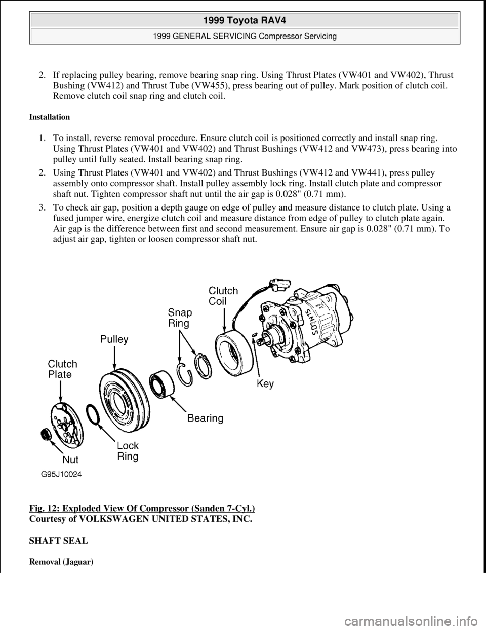
Fig. 12: Exploded View Of Compressor (Sanden 7
-Cyl.)
Courtesy of VOLKSWAGEN UNITED STATES, INC.
SHAFT SEAL
Removal (Jaguar)
1999 Toyota RAV4
1999 GENERAL SERVICING Compressor Servicing
Microsoft
Sunday, November 22, 2009 10:31:50 AMPage 24 © 2005 Mitchell Repair Information Company, LLC.
Page 471 of 1632
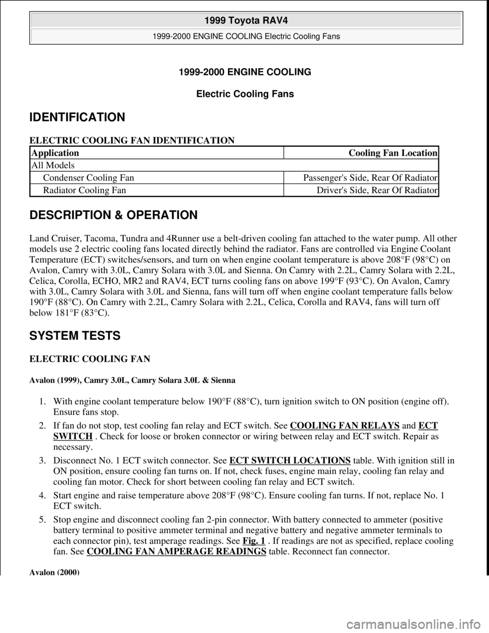
1999-2000 ENGINE COOLING
Electric Cooling Fans
IDENTIFICATION
ELECTRIC COOLING FAN IDENTIFICATION
DESCRIPTION & OPERATION
Land Cruiser, Tacoma, Tundra and 4Runner use a belt-driven cooling fan attached to the water pump. All other
models use 2 electric cooling fans located directly behind the radiator. Fans are controlled via Engine Coolant
Temperature (ECT) switches/sensors, and turn on when engine coolant temperature is above 208°F (98°C) on
Avalon, Camry with 3.0L, Camry Solara with 3.0L and Sienna. On Camry with 2.2L, Camry Solara with 2.2L,
Celica, Corolla, ECHO, MR2 and RAV4, ECT turns cooling fans on above 199°F (93°C). On Avalon, Camry
with 3.0L, Camry Solara with 3.0L and Sienna, fans will turn off when engine coolant temperature falls below
190°F (88°C). On Camry with 2.2L, Camry Solara with 2.2L, Celica, Corolla and RAV4, fans will turn off
below 181°F (83°C).
SYSTEM TESTS
ELECTRIC COOLING FAN
Avalon (1999), Camry 3.0L, Camry Solara 3.0L & Sienna
1. With engine coolant temperature below 190°F (88°C), turn ignition switch to ON position (engine off).
Ensure fans stop.
2. If fan do not stop, test cooling fan relay and ECT switch. See COOLING FAN RELAYS
and ECT
SWITCH . Check for loose or broken connector or wiring between relay and ECT switch. Repair as
necessary.
3. Disconnect No. 1 ECT switch connector. See ECT SWITCH LOCATIONS
table. With ignition still in
ON position, ensure cooling fan turns on. If not, check fuses, engine main relay, cooling fan relay and
cooling fan motor. Check for short between cooling fan relay and ECT switch.
4. Start engine and raise temperature above 208°F (98°C). Ensure cooling fan turns. If not, replace No. 1
ECT switch.
5. Stop engine and disconnect cooling fan 2-pin connector. With battery connected to ammeter (positive
battery terminal to positive ammeter terminal and negative battery and negative ammeter terminals to
each connector pin), test amperage readings. See Fig. 1
. If readings are not as specified, replace cooling
fan. See COOLING FAN AMPERAGE READINGS
table. Reconnect fan connector.
Avalon (2000)
ApplicationCooling Fan Location
All Models
Condenser Cooling FanPassenger's Side, Rear Of Radiator
Radiator Cooling FanDriver's Side, Rear Of Radiator
1999 Toyota RAV4
1999-2000 ENGINE COOLING Electric Cooling Fans
1999 Toyota RAV4
1999-2000 ENGINE COOLING Electric Cooling Fans
Microsoft
Sunday, November 22, 2009 10:21:41 AMPage 1 © 2005 Mitchell Repair Information Company, LLC.
Microsoft
Sunday, November 22, 2009 10:21:45 AMPage 1 © 2005 Mitchell Repair Information Company, LLC.
Page 474 of 1632
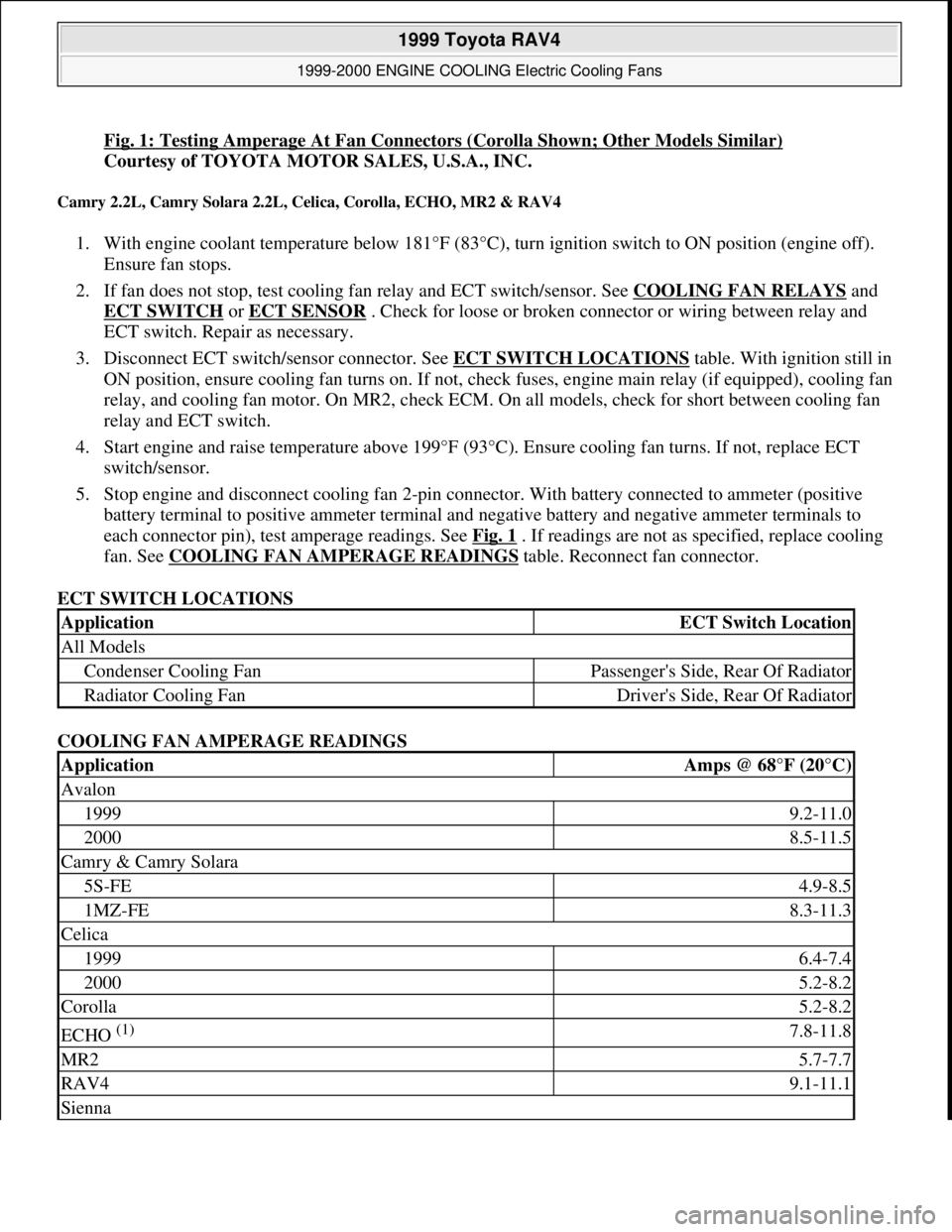
Fig. 1: Testing Amperage At Fan Connectors (Corolla Shown; Other Models Similar)
Courtesy of TOYOTA MOTOR SALES, U.S.A., INC.
Camry 2.2L, Camry Solara 2.2L, Celica, Corolla, ECHO, MR2 & RAV4
1. With engine coolant temperature below 181°F (83°C), turn ignition switch to ON position (engine off).
Ensure fan stops.
2. If fan does not stop, test cooling fan relay and ECT switch/sensor. See COOLING FAN RELAYS
and
ECT SWITCH
or ECT SENSOR . Check for loose or broken connector or wiring between relay and
ECT switch. Repair as necessary.
3. Disconnect ECT switch/sensor connector. See ECT SWITCH LOCATIONS
table. With ignition still in
ON position, ensure cooling fan turns on. If not, check fuses, engine main relay (if equipped), cooling fan
relay, and cooling fan motor. On MR2, check ECM. On all models, check for short between cooling fan
relay and ECT switch.
4. Start engine and raise temperature above 199°F (93°C). Ensure cooling fan turns. If not, replace ECT
switch/sensor.
5. Stop engine and disconnect cooling fan 2-pin connector. With battery connected to ammeter (positive
battery terminal to positive ammeter terminal and negative battery and negative ammeter terminals to
each connector pin), test amperage readings. See Fig. 1
. If readings are not as specified, replace cooling
fan. See COOLING FAN AMPERAGE READINGS
table. Reconnect fan connector.
ECT SWITCH LOCATIONS
COOLING FAN AMPERAGE READINGS
ApplicationECT Switch Location
All Models
Condenser Cooling FanPassenger's Side, Rear Of Radiator
Radiator Cooling FanDriver's Side, Rear Of Radiator
ApplicationAmps @ 68°F (20°C)
Avalon
19999.2-11.0
20008.5-11.5
Camry & Camry Solara
5S-FE4.9-8.5
1MZ-FE8.3-11.3
Celica
19996.4-7.4
20005.2-8.2
Corolla5.2-8.2
ECHO (1) 7.8-11.8
MR25.7-7.7
RAV49.1-11.1
Sienna
1999 Toyota RAV4
1999-2000 ENGINE COOLING Electric Cooling Fans
Microsoft
Sunday, November 22, 2009 10:21:41 AMPage 4 © 2005 Mitchell Repair Information Company, LLC.
Page 475 of 1632
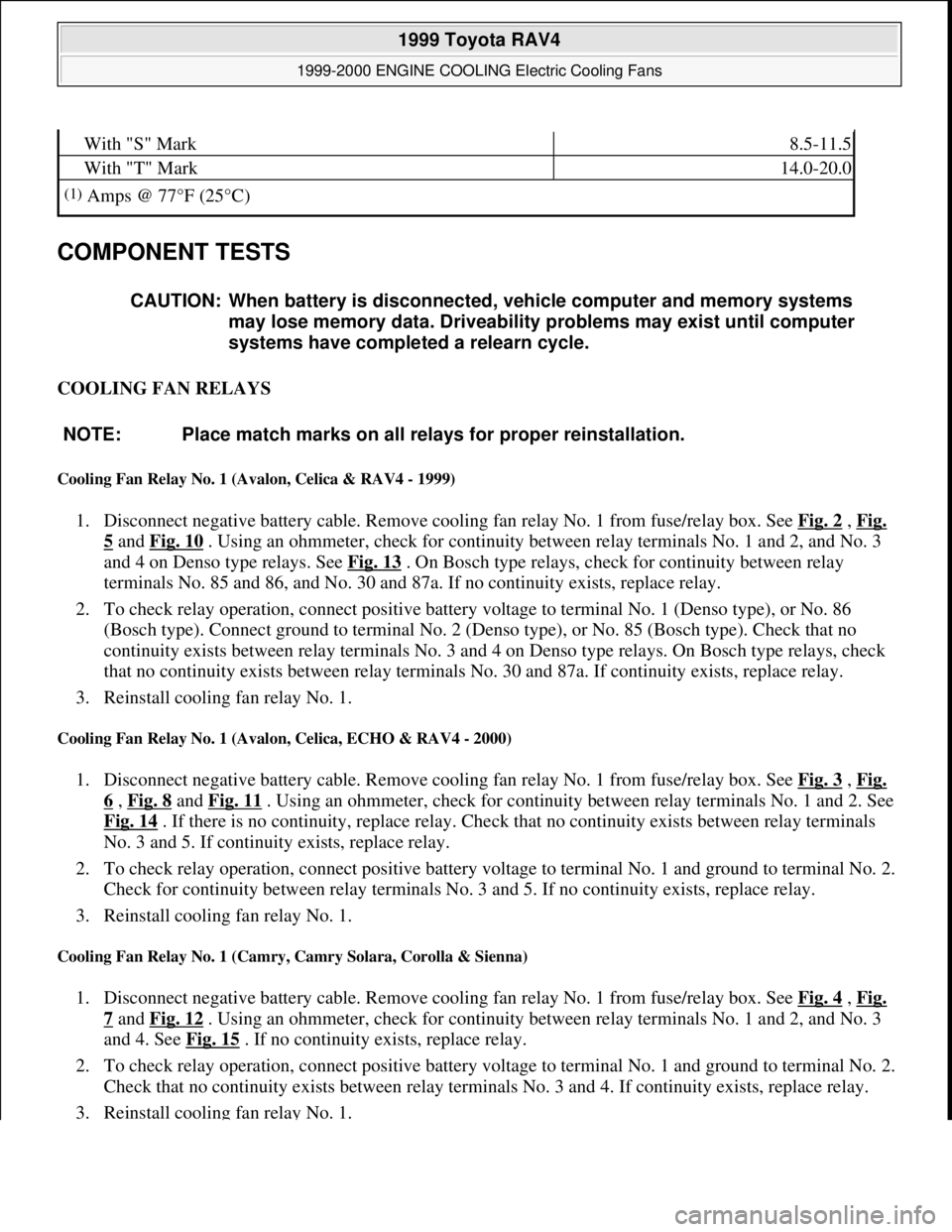
COMPONENT TESTS
COOLING FAN RELAYS
Cooling Fan Relay No. 1 (Avalon, Celica & RAV4 - 1999)
1. Disconnect negative battery cable. Remove cooling fan relay No. 1 from fuse/relay box. See Fig. 2 , Fig.
5 and Fig. 10 . Using an ohmmeter, check for continuity between relay terminals No. 1 and 2, and No. 3
and 4 on Denso type relays. See Fig. 13
. On Bosch type relays, check for continuity between relay
terminals No. 85 and 86, and No. 30 and 87a. If no continuity exists, replace relay.
2. To check relay operation, connect positive battery voltage to terminal No. 1 (Denso type), or No. 86
(Bosch type). Connect ground to terminal No. 2 (Denso type), or No. 85 (Bosch type). Check that no
continuity exists between relay terminals No. 3 and 4 on Denso type relays. On Bosch type relays, check
that no continuity exists between relay terminals No. 30 and 87a. If continuity exists, replace relay.
3. Reinstall cooling fan relay No. 1.
Cooling Fan Relay No. 1 (Avalon, Celica, ECHO & RAV4 - 2000)
1. Disconnect negative battery cable. Remove cooling fan relay No. 1 from fuse/relay box. See Fig. 3 , Fig.
6 , Fig. 8 and Fig. 11 . Using an ohmmeter, check for continuity between relay terminals No. 1 and 2. See
Fig. 14
. If there is no continuity, replace relay. Check that no continuity exists between relay terminals
No. 3 and 5. If continuity exists, replace relay.
2. To check relay operation, connect positive battery voltage to terminal No. 1 and ground to terminal No. 2.
Check for continuity between relay terminals No. 3 and 5. If no continuity exists, replace relay.
3. Reinstall cooling fan relay No. 1.
Cooling Fan Relay No. 1 (Camry, Camry Solara, Corolla & Sienna)
1. Disconnect negative battery cable. Remove cooling fan relay No. 1 from fuse/relay box. See Fig. 4 , Fig.
7 and Fig. 12 . Using an ohmmeter, check for continuity between relay terminals No. 1 and 2, and No. 3
and 4. See Fig. 15
. If no continuity exists, replace relay.
2. To check relay operation, connect positive battery voltage to terminal No. 1 and ground to terminal No. 2.
Check that no continuity exists between relay terminals No. 3 and 4. If continuity exists, replace relay.
3. Reinstall cooling fan relay No. 1.
With "S" Mark8.5-11.5
With "T" Mark14.0-20.0
(1)Amps @ 77°F (25°C)
CAUTION: When battery is disconnected, vehicle computer and memory systems
may lose memory data. Driveability problems may exist until computer
systems have completed a relearn cycle.
NOTE: Place match marks on all relays for proper reinstallation.
1999 Toyota RAV4
1999-2000 ENGINE COOLING Electric Cooling Fans
Microsoft
Sunday, November 22, 2009 10:21:41 AMPage 5 © 2005 Mitchell Repair Information Company, LLC.
Page 476 of 1632
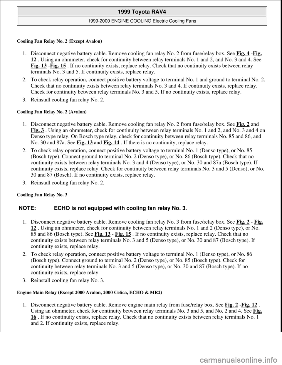
Cooling Fan Relay No. 2 (Except Avalon)
1. Disconnect negative battery cable. Remove cooling fan relay No. 2 from fuse/relay box. See Fig. 4 -Fig.
12 . Using an ohmmeter, check for continuity between relay terminals No. 1 and 2, and No. 3 and 4. See
Fig. 13
-Fig. 15 . If no continuity exists, replace relay. Check that no continuity exists between relay
terminals No. 3 and 5. If continuity exists, replace relay.
2. To check relay operation, connect positive battery voltage to terminal No. 1 and ground to terminal No. 2.
Check that no continuity exists between relay terminals No. 3 and 4. If continuity exists, replace relay.
Check for continuity between relay terminals No. 3 and 5. If no continuity exists, replace relay.
3. Reinstall cooling fan relay No. 2.
Cooling Fan Relay No. 2 (Avalon)
1. Disconnect negative battery cable. Remove cooling fan relay No. 2 from fuse/relay box. See Fig. 2 and
Fig. 3
. Using an ohmmeter, check for continuity between relay terminals No. 1 and 2, and No. 3 and 4 on
Denso type relay. On Bosch type relay, check for continuity between relay terminals No. 85 and 86, and
No. 30 and 87a. See Fig. 13
and Fig. 14 . If there is no continuity, replace relay.
2. To check relay operation, connect positive battery voltage to terminal No. 1 (Denso type), or No. 85
(Bosch type). Connect ground to terminal No. 2 (Denso type), or No. 86 (Bosch type). Check that no
continuity exists between relay terminals No. 3 and 4 (Denso type), or No. 30 and 87a (Bosch type). If
continuity exists, replace relay. Check for continuity between relay terminals No. 3 and 5 (Denso), or No.
30 and 87 (Bosch). If no continuity exists, replace relay.
3. Reinstall cooling fan relay No. 2.
Cooling Fan Relay No. 3
1. Disconnect negative battery cable. Remove cooling fan relay No. 3 from fuse/relay box. See Fig. 2 - Fig.
12 . Using an ohmmeter, check for continuity between relay terminals No. 1 and 2 (Denso type), or No.
85 and 86 (Bosch type). See Fig. 13
- Fig. 15 . If no continuity exists, replace relay. Check that no
continuity exists between relay terminals No. 3 and 5 (Denso type), or No. 30 and 87 (Bosch type). If
continuity exists, replace relay.
2. To check relay operation, connect positive battery voltage to terminal No. 1 (Denso type), or No. 86
(Bosch type). Connect ground to terminal No. 2 (Denso type), or No. 85 (Bosch type). Check for
continuity between relay terminals No. 3 and 5 (Denso type), or No. 30 and 87 (Bosch type). If no
continuity exists, replace relay.
3. Reinstall cooling fan relay No. 3.
Engine Main Relay (Except 2000 Avalon, 2000 Celica, ECHO & MR2)
1. Disconnect negative battery cable. Remove engine main relay from fuse/relay box. See Fig. 2 -Fig. 12 .
Using an ohmmeter, check for continuity between relay terminals No. 3 and 5, and No. 2 and 4. See Fig.
16 . If no continuity exists, replace relay. Check that no continuity exists between relay terminals No. 1
and 2. If continuit
y exists, replace relay. NOTE: ECHO is not equipped with cooling fan relay No. 3.
1999 Toyota RAV4
1999-2000 ENGINE COOLING Electric Cooling Fans
Microsoft
Sunday, November 22, 2009 10:21:41 AMPage 6 © 2005 Mitchell Repair Information Company, LLC.
Page 537 of 1632
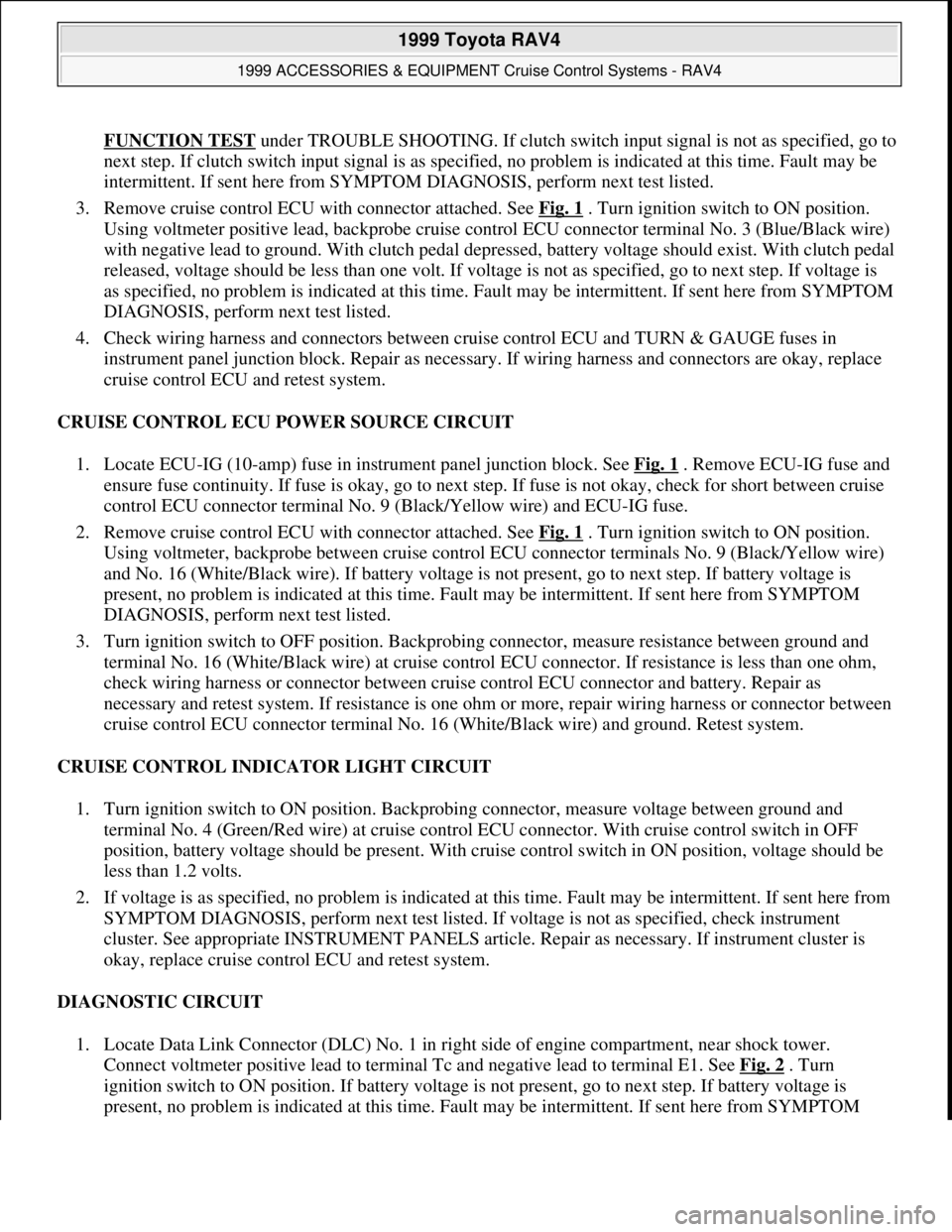
FUNCTION TEST under TROUBLE SHOOTING. If clutch switch input signal is not as specified, go to
next step. If clutch switch input signal is as specified, no problem is indicated at this time. Fault may be
intermittent. If sent here from SYMPTOM DIAGNOSIS, perform next test listed.
3. Remove cruise control ECU with connector attached. See Fig. 1
. Turn ignition switch to ON position.
Using voltmeter positive lead, backprobe cruise control ECU connector terminal No. 3 (Blue/Black wire)
with negative lead to ground. With clutch pedal depressed, battery voltage should exist. With clutch pedal
released, voltage should be less than one volt. If voltage is not as specified, go to next step. If voltage is
as specified, no problem is indicated at this time. Fault may be intermittent. If sent here from SYMPTOM
DIAGNOSIS, perform next test listed.
4. Check wiring harness and connectors between cruise control ECU and TURN & GAUGE fuses in
instrument panel junction block. Repair as necessary. If wiring harness and connectors are okay, replace
cruise control ECU and retest system.
CRUISE CONTROL ECU POWER SOURCE CIRCUIT
1. Locate ECU-IG (10-amp) fuse in instrument panel junction block. See Fig. 1
. Remove ECU-IG fuse and
ensure fuse continuity. If fuse is okay, go to next step. If fuse is not okay, check for short between cruise
control ECU connector terminal No. 9 (Black/Yellow wire) and ECU-IG fuse.
2. Remove cruise control ECU with connector attached. See Fig. 1
. Turn ignition switch to ON position.
Using voltmeter, backprobe between cruise control ECU connector terminals No. 9 (Black/Yellow wire)
and No. 16 (White/Black wire). If battery voltage is not present, go to next step. If battery voltage is
present, no problem is indicated at this time. Fault may be intermittent. If sent here from SYMPTOM
DIAGNOSIS, perform next test listed.
3. Turn ignition switch to OFF position. Backprobing connector, measure resistance between ground and
terminal No. 16 (White/Black wire) at cruise control ECU connector. If resistance is less than one ohm,
check wiring harness or connector between cruise control ECU connector and battery. Repair as
necessary and retest system. If resistance is one ohm or more, repair wiring harness or connector between
cruise control ECU connector terminal No. 16 (White/Black wire) and ground. Retest system.
CRUISE CONTROL INDICATOR LIGHT CIRCUIT
1. Turn ignition switch to ON position. Backprobing connector, measure voltage between ground and
terminal No. 4 (Green/Red wire) at cruise control ECU connector. With cruise control switch in OFF
position, battery voltage should be present. With cruise control switch in ON position, voltage should be
less than 1.2 volts.
2. If voltage is as specified, no problem is indicated at this time. Fault may be intermittent. If sent here from
SYMPTOM DIAGNOSIS, perform next test listed. If voltage is not as specified, check instrument
cluster. See appropriate INSTRUMENT PANELS article. Repair as necessary. If instrument cluster is
okay, replace cruise control ECU and retest system.
DIAGNOSTIC CIRCUIT
1. Locate Data Link Connector (DLC) No. 1 in right side of engine compartment, near shock tower.
Connect voltmeter positive lead to terminal Tc and negative lead to terminal E1. See Fig. 2
. Turn
ignition switch to ON position. If battery voltage is not present, go to next step. If battery voltage is
present, no problem is indicated at this time. Fault ma
y be intermittent. If sent here from SYMPTOM
1999 Toyota RAV4
1999 ACCESSORIES & EQUIPMENT Cruise Control Systems - RAV4
Microsoft
Sunday, November 22, 2009 10:52:01 AMPage 13 © 2005 Mitchell Repair Information Company, LLC.
Page 541 of 1632
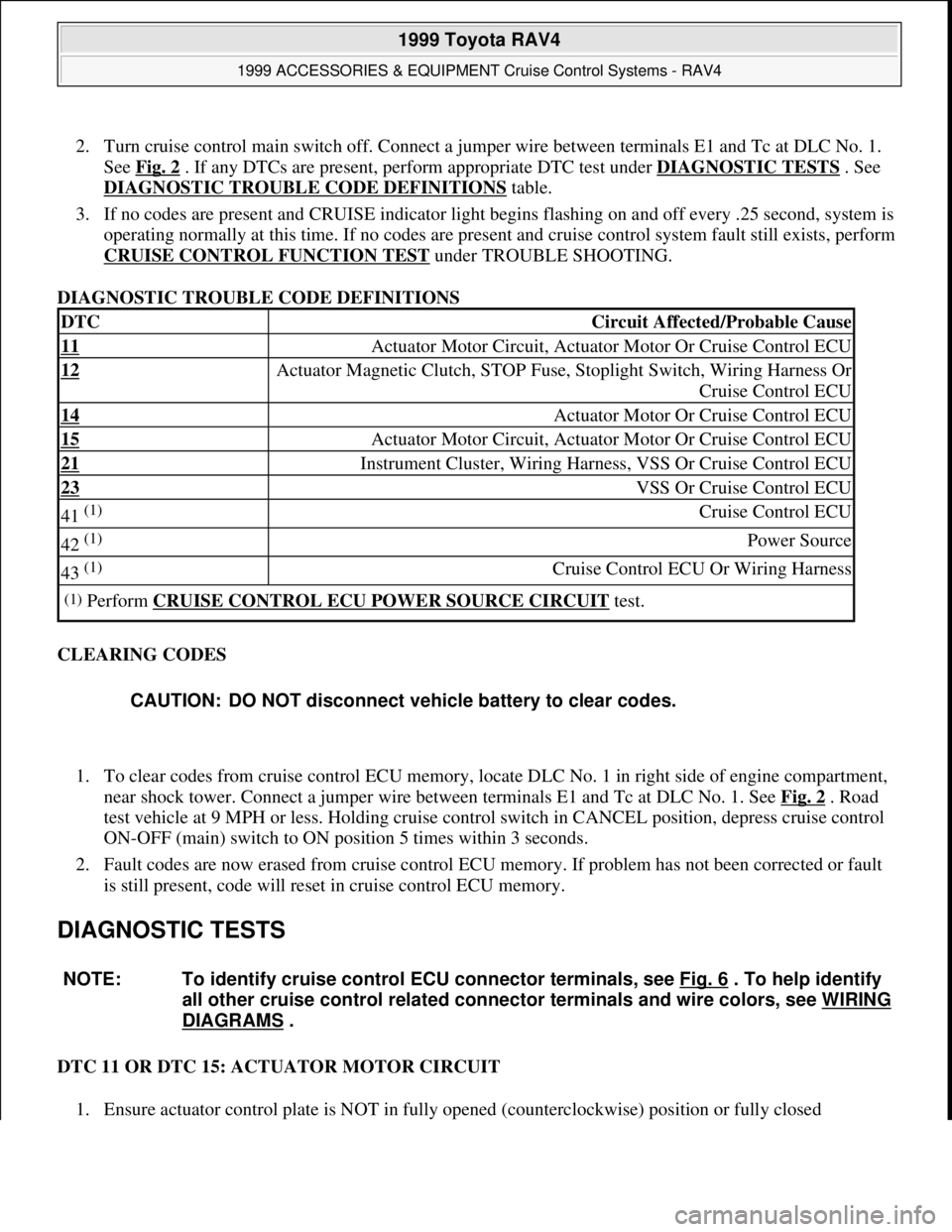
2. Turn cruise control main switch off. Connect a jumper wire between terminals E1 and Tc at DLC No. 1.
See Fig. 2
. If any DTCs are present, perform appropriate DTC test under DIAGNOSTIC TESTS . See
DIAGNOSTIC TROUBLE CODE DEFINITIONS
table.
3. If no codes are present and CRUISE indicator light begins flashing on and off every .25 second, system is
operating normally at this time. If no codes are present and cruise control system fault still exists, perform
CRUISE CONTROL FUNCTION TEST
under TROUBLE SHOOTING.
DIAGNOSTIC TROUBLE CODE DEFINITIONS
CLEARING CODES
1. To clear codes from cruise control ECU memory, locate DLC No. 1 in right side of engine compartment,
near shock tower. Connect a jumper wire between terminals E1 and Tc at DLC No. 1. See Fig. 2
. Road
test vehicle at 9 MPH or less. Holding cruise control switch in CANCEL position, depress cruise control
ON-OFF (main) switch to ON position 5 times within 3 seconds.
2. Fault codes are now erased from cruise control ECU memory. If problem has not been corrected or fault
is still present, code will reset in cruise control ECU memory.
DIAGNOSTIC TESTS
DTC 11 OR DTC 15: ACTUATOR MOTOR CIRCUIT
1. Ensure actuator control plate is NOT in full
y opened (counterclockwise) position or fully closed
DTCCircuit Affected/Probable Cause
11 Actuator Motor Circuit, Actuator Motor Or Cruise Control ECU
12 Actuator Magnetic Clutch, STOP Fuse, Stoplight Switch, Wiring Harness Or
Cruise Control ECU
14 Actuator Motor Or Cruise Control ECU
15 Actuator Motor Circuit, Actuator Motor Or Cruise Control ECU
21 Instrument Cluster, Wiring Harness, VSS Or Cruise Control ECU
23 VSS Or Cruise Control ECU
41 (1) Cruise Control ECU
42 (1) Power Source
43 (1) Cruise Control ECU Or Wiring Harness
(1)Perform CRUISE CONTROL ECU POWER SOURCE CIRCUIT test.
CAUTION: DO NOT disconnect vehicle battery to clear codes.
NOTE: To identify cruise control ECU connector terminals, see Fig. 6
. To help identify
all other cruise control related connector terminals and wire colors, see WIRING
DIAGRAMS .
1999 Toyota RAV4
1999 ACCESSORIES & EQUIPMENT Cruise Control Systems - RAV4
Microsoft
Sunday, November 22, 2009 10:52:01 AMPage 17 © 2005 Mitchell Repair Information Company, LLC.