fuse TOYOTA RAV4 1996 Service Repair Manual
[x] Cancel search | Manufacturer: TOYOTA, Model Year: 1996, Model line: RAV4, Model: TOYOTA RAV4 1996Pages: 1632, PDF Size: 41.64 MB
Page 2 of 1632
Fig. 1: Locating ABS Components
Courtesy of TOYOTA MOTOR SALES, U.S.A., INC.
OPERATION
Under normal driving conditions, ABS functions as a standard brake system. With detection of wheel lock-up,
short pedal pulsations occurring in rapid succession will be felt in brake pedal. Pedal pulsation will continue
until there is no longer a need for ABS function or until vehicle speed falls below 3 MPH. Maintaining a
constant force on the brake pedal provides shortest stopping distance.
BLEEDING BRAKE SYSTEM
MASTER CYLINDER
Ensure brake fluid reservoir is full. Disconnect brakelines from master cylinder. Have an assistant slowly
depress brake pedal and hold. Block off outlet ports on master cylinder with finger, then have assistant release
brake pedal. Repeat 3 or 4 times or until master cylinder is bled.
BRAKELINES
Install bleeder hose with container of clean brake fluid on wheel cylinder or caliper. Depress brake pedal several
times and hold, then loosen bleeder valve. Tighten bleeder valve when fluid flow stops, then release brake
pedal. Repeat until air bubbles are no longer present for each wheel.
TROUBLE SHOOTING
PRELIMINARY INSPECTION
Begin diagnosis with a basic visual inspection of brake fluid level, tire size and other mechanical brake system
components which may affect anti-lock operation. Check system sensors, wire harnesses and connectors for
proper installation, routing and connection. Ensure all system fuses are okay. Repair as necessary. NOTE: For more information on brake system, see DISC & DRUM
- FWD CARS article.
CAUTION: See ANTI-LOCK BRAKE SAFETY PRECAUTIONS article in GENERAL
INFORMATION.
CAUTION: Brake fluid will damage painted surfaces. If brake fluid contacts a painted
surface, wipe off immediately and clean with alcohol. Use only DOT 3
brake fluid from a sealed container. DO NOT mix brake fluid with any other
type.
NOTE: Bleed brakes from farthest wheel first to closest wheel.
1999 Toyota RAV4
1999-2000 BRAKES Anti-Lock - RAV4
Microsoft
Sunday, November 22, 2009 10:06:17 AMPage 2 © 2005 Mitchell Repair Information Company, LLC.
Page 3 of 1632
If cause of faulty operation cannot be located with basic diagnosis, ABS electronic control system must be
checked. See DIAGNOSIS & TESTING
.
When ignition is turned on, ABS warning light should come on, then go out after 3 seconds. If ABS warning
light does not operate as specified, go to ABS WARNING LIGHT under DIAGNOSIS & TESTING
.
DIAGNOSIS & TESTING
RETRIEVING DIAGNOSTIC TROUBLE CODES
ABS Warning Light Diagnostics
1. Ensure battery voltage is 12 volts. Turn ignition switch to ON position. ABS warning light should
illuminate, then go out after 3 seconds. If ABS warning light does not illuminate, check fuse, bulb, and
wiring harness. See ABS WARNING LIGHT
.
2. Remove short pin from DLC1. DLC1 is located in engine compartment, on left side of engine. See Fig.
2 . Using a jumper wire, jumper DLC1 terminals Tc and E1 . If a malfunction is detected, ABS warning
light will begin to flash a 2-digit Diagnostic Trouble Code (DTC). First number of blinks will equal first
digit in DTC. After a 1.5-second pause, second number of blinks will equal second digit in DTC.
3. If 2 or more DTCs are stored, there will be a 2.5-second pause between each DTC. After all DTCs are
flashed, there will be a 4 second pause and all DTCs will repeat. If ABS system is functioning properly,
ABS warning light will blink 2 times per second. For code definitions, see DTC DEFINITIONS
. For
DTC diagnosis, see DIAGNOSTIC TESTS
.
4. After replacing or repairing components, clear DTCs. If battery cables were disconnected during repairs,
all DTCs will be erased. If battery cables were not disconnected during repairs, see CLEARING DTCS
.
DTC DEFINITIONS NOTE: DO NOT start engine when retrieving DTCs.
NOTE: Speed sensor diagnostics and code retrieval use different DLC1 terminals to
access DTCs. If a speed sensor or speed sensor circuit problem is suspected,
see SPEED SENSOR DIAGNOSTICS
.
DTCCircuit/Malfunction
ABS-Related DTCs (1)
11 Open In ABS Solenoid Relay Circuit
12 Short In ABS Solenoid Relay Circuit
13 Open In ABS Pump Motor Relay Circuit
14 Short In ABS Pump Motor Relay Circuit
21 Open/Shorted RF Solenoid, Defective ABS
Actuator
22 Open/Shorted LF Solenoid, Defective ABS
Actuator
1999 Toyota RAV4
1999-2000 BRAKES Anti-Lock - RAV4
Microsoft
Sunday, November 22, 2009 10:06:17 AMPage 3 © 2005 Mitchell Repair Information Company, LLC.
Page 5 of 1632
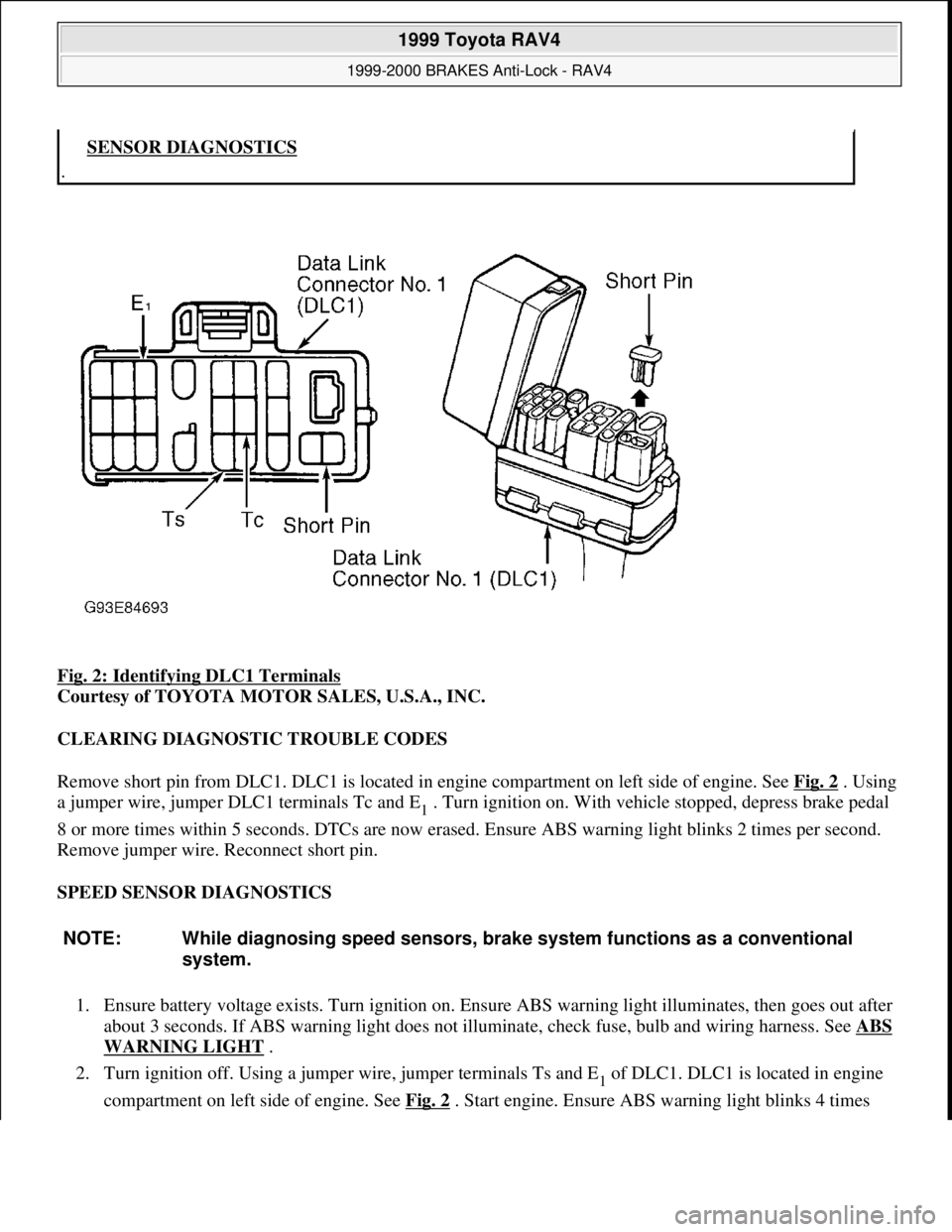
Fig. 2: Identifying DLC1 Terminals
Courtesy of TOYOTA MOTOR SALES, U.S.A., INC.
CLEARING DIAGNOSTIC TROUBLE CODES
Remove short pin from DLC1. DLC1 is located in engine compartment on left side of engine. See Fig. 2
. Using
a jumper wire, jumper DLC1 terminals Tc and E
1 . Turn ignition on. With vehicle stopped, depress brake pedal
8 or more times within 5 seconds. DTCs are now erased. Ensure ABS warning light blinks 2 times per second.
Remove jumper wire. Reconnect short pin.
SPEED SENSOR DIAGNOSTICS
1. Ensure battery voltage exists. Turn ignition on. Ensure ABS warning light illuminates, then goes out after
about 3 seconds. If ABS warning light does not illuminate, check fuse, bulb and wiring harness. See ABS
WARNING LIGHT .
2. Turn ignition off. Using a jumper wire, jumper terminals Ts and E
1 of DLC1. DLC1 is located in engine
compartment on left side of en
gine. See Fig. 2. Start engine. Ensure ABS warning light blinks 4 times
.SENSOR DIAGNOSTICS
NOTE: While diagnosing speed sensors, brake system functions as a conventional
system.
1999 Toyota RAV4
1999-2000 BRAKES Anti-Lock - RAV4
Microsoft
Sunday, November 22, 2009 10:06:17 AMPage 5 © 2005 Mitchell Repair Information Company, LLC.
Page 6 of 1632
per second. If ABS light does not blink, go to ABS WARNING LIGHT. If ABS warning light blinks,
go to next step.
3. Drive vehicle straight ahead above 28 MPH for several seconds. Stop vehicle. Jumper terminals Tc and
E
1 of DLC1. See Fig. 2 . If all sensors are okay, a normal DTC is displayed (ABS warning light blinks 2
times a second). If a malfunction is detected, ABS warning light will begin to flash a 2-digit DTC. First
number of blinks will equal first digit in a DTC. After a 1.5-second pause, second number of blinks will
equal second digit in a DTC.
4. If 2 or more DTCs are stored, there will be a 2.5-second pause between each DTC. After all DTCs are
flashed, there will be a 4 second pause and all DTCs will repeat.
5. Record DTCs. Turn ignition off. Repair as necessary. See DTC DEFINITIONS
. Remove jumper wire
from DLC1. Clear DTCs. See CLEARING DTCS
.
ABS WARNING LIGHT
Circuit Description
If ABS ECU detects a system malfunction, ABS ECU illuminates ABS warning light while at the same time
prohibiting ABS control. At this time, ABS ECU records a DTC in memory. After removing short pin from
DLC1, connecting terminals Tc and E
1 of DLC1 causes ABS warning light to blink and output a DTC. See Fig.
2 .
Diagnostic Procedure
1. If ABS warning light stays on, go to step 3 . If ABS warning light does not illuminate, check fuse, light
bulb and wiring. Repair or replace as necessary. If bulb is okay, diagnose combination meter (instrument
panel). See appropriate INSTRUMENT PANELS article in ACCESSORIES & EQUIPMENT. If no
problems were found, go to next step.
2. Check ABS control relay. See SOLENOID RELAY SECTION
under ABS CONTROL RELAY under
COMPONENT TESTS. Replace as necessary. If ABS control relay is okay, go to next step.
3. Retrieve DTCs. See RETRIEVING DTCS
under DIAGNOSIS & TESTING. If DTC is present, perform
appropriate test under DIAGNOSTIC TESTS. If DTC is not present, and ABS warning light goes off
when short pin is removed, go to next step. If ABS warning light does not turn off, check for short circuit
in wiring harness between ABS warning light, DLC1 and ABS ECU. Repair as necessary. See WIRING
DIAGRAMS .
4. Check ABS control relay. See SOLENOID RELAY SECTION
under ABS CONTROL RELAY under
COMPONENT TESTS. Replace relay as necessary. If relay is okay, check for short circuit in wiring
harness between DLC1 and ABS control relay. Repair as necessary. See WIRING DIAGRAMS
.
TC TERMINAL
Circuit Description
Connecting terminals Tc and E1 of DLC1 causes ABS warning light to blink and output a DTC. See Fig. 2 .
Diagnostic Procedure
1999 Toyota RAV4
1999-2000 BRAKES Anti-Lock - RAV4
Microsoft
Sunday, November 22, 2009 10:06:17 AMPage 6 © 2005 Mitchell Repair Information Company, LLC.
Page 10 of 1632
wiring harness between ABS control relay and DLC1. Repair or replace as necessary. See WIRING
DIAGRAMS .
2. If ABS warning light is on, go to next step. If ABS warning light is off, check for open or short circuit in
wiring harness between ECU-IG fuse and ABS ECU. Repair as necessary. See WIRING DIAGRAMS
.
3. Start engine and check charging system voltage. If voltage is 10-16 volts, go to next step. If voltage is not
10-16 volts, diagnose charging system. Repair as necessary.
4. Turn ignition off. Disconnect appropriate ABS ECU connector supporting IG1 terminal. See Fig. 3
. Turn
ignition switch to ON position. Ensure ABS warning light turns off. If light turns off, replace ABS ECU.
If light does not turn off, check for short circuit in wiring harness between combination meter (instrument
panel) and ABS ECU, or between combination meter and DLC1. Repair as necessary. See WIRING
DIAGRAMS .
DIAGNOSTIC TESTS
DTC 11 & DTC 12: ABS CONTROL (SOLENOID) RELAY CIRCUIT
Circuit Description
This relay supplies power to each ABS solenoid. After ignition switch is turned to ON position, if initial check
is okay, this relay turns on. If malfunction occurs in ABS control relay circuit, ABS ECU cuts off current to
ABS control relay and prohibits ABS control.
DTC Detecting Condition
Detection of following conditions may set DTC 11 or DTC 12 if condition occurs for .2 seconds or more:
If voltage at ABS control relay connector terminal A9-1 is less than 1.5 volts and voltage at connector
terminal A9-5 is zero volts, DTC 11 may set.
If voltage at ABS control relay connector terminal A9-1 is 10-14 volts and voltage at connector terminal
A9-5 is 10-14 volts, DTC 12 may set.
Diagnostic Procedure
1. Disconnect ABS control relay 6-pin connector A9, located in engine compartment at front of vehicle. See
Fig. 1
. Measure voltage between connector terminals A9-2 and A9-6. See Fig. 4 . If voltage is 10-14
volts, go to next step. If voltage is not 10-14 volts, repair wiring harness between ground, battery and
ABS control relay.
2. Measure resistance between ABS control relay terminal A9-5 and appropriate ABS ECU terminals. See
ABS ECU
-TO-ACTUATOR CIRCUIT IDENTIFICATION/RESISTANCE VALUES . See Fig. 3 .
If resistance on every circuit is between 26-40 ohms, go to next step. If resistance is not as specified,
check for open or short circuit in appropriate wiring between ABS control relay, ABS actuator and ABS
ECU. See WIRING DIAGRAMS
. Repair as necessary. If wiring is okay, replace ABS actuator.
ABS ECU-TO-ACTUATOR CIRCUIT IDENTIFICATION/RESISTANCE VALUES
CircuitABS ECU
Connector/TerminalWire Color
1999 Toyota RAV4
1999-2000 BRAKES Anti-Lock - RAV4
Microsoft
Sunday, November 22, 2009 10:06:17 AMPage 10 © 2005 Mitchell Repair Information Company, LLC.
Page 17 of 1632
DTC Detecting Condition
Detection of the following condition may set DTC 41:
At vehicle speed of about 2 MPH or more, if voltage at ABS ECU terminal IG1 is less than 9.5 volts for
10 seconds or more, DTC 41 may set.
Diagnostic Procedure
1. Check charging system voltage. If voltage is 10-14 volts, system is okay. Go to next step. If voltage is not
10-14 volts, repair charging system. Ensure system fuses are okay.
2. Turn ignition off. Remove ABS ECU. Do not disconnect electrical connectors. Turn ignition switch to
ON position. Measure voltage between terminals IG1 and GND at ABS ECU harness connector. See Fig.
3 . If voltage is 10-14 volts, turn ignition off. Condition may be intermittent. Check ABS ECU connectors
for poor connection or damage. Repair as necessary. If connectors are okay, replace ABS ECU. If voltage
is not as specified, go to next step.
3. Measure resistance between ground and GND terminals at ABS ECU harness connector. See Fig. 3
. If
resistance is one ohm or less, go to next step. If resistance is more than one ohm, repair ground circuit
wiring. See WIRING DIAGRAMS
.
4. Remove ECU-IG fuse from instrument panel junction block. If fuse is blown, check for short circuit in all
wiring harnesses and components connected to ECU-IG fuse (ECM, A/C, cruise control, deceleration
sensor, combination meter, sun roof, shift lock, transmission pattern select switch). See WIRING
DIAGRAMS . Repair as necessary. If fuse is not blown, check for open circuit in wiring harness between
battery and ABS ECU. Repair as necessary.
DTC 43 & DTC 45: DECELERATION SENSOR MALFUNCTION (4WD MODELS ONLY)
DTC Detecting Conditions
Detection of the following conditions may set DTCs 43 or 45:
On 2-door models, if output voltage from deceleration sensor does not change for 16 consecutive times or
more when vehicle speed is decreased from 19 MPH to zero MPH, DTC 43 will set.
On 4-door models, after battery cables are connected, if input from deceleration sensor does not change at
one cycle (zero MPH to 19 MPH or more, then back to zero) for 16 consecutive times, DTC 43 will set.
When brake pedal is not depressed at vehicle speed of 3 MPH or more, and forward and backward force
(force of more than 0.4 "G") is detected for 30 seconds or more, DTC 43 will set.
On 2-door models, at vehicle speed of 19 MPH or more, if deceleration sensor output and vehicle
acceleration from wheel speed remains abnormally different for one minute or more, DTC 45 will set.
Diagnostic Procedure
1. Check deceleration sensor. See DECELERATION SENSOR CHECK under COMPONENT TESTS.
Replace sensor as necessary. If sensor is okay, go to next step.
2. Check for open or short circuit in wiring harness between deceleration sensor and ABS ECU. See
WIRING DIAGRAMS
. Repair as necessary. If wiring harness is okay, replace ABS ECU.
1999 Toyota RAV4
1999-2000 BRAKES Anti-Lock - RAV4
Microsoft
Sunday, November 22, 2009 10:06:17 AMPage 17 © 2005 Mitchell Repair Information Company, LLC.
Page 26 of 1632
1. Check charging system voltage. Ensure 10-14 volts is present. If charging system voltage is okay, go to
next step. If charging system voltage is not okay, check and repair charging system.
2. Turn ignition switch to ON position. Ensure ABS warning light comes on, then goes out after 3 seconds.
If ABS warning light does not illuminate, check fuse, bulb, and wiring harness. See ABS WARNING
LIGHT under DIAGNOSIS & TESTING. Turn ignition off.
3. Using a jumper wire, jumper terminals Ts and E
1 of DLC1. DLC1 is located in engine compartment on
left side of engine. See Fig. 2
. Ensure ABS warning light blinks 4 times per second. If ABS light does
not blink, go to ABS WARNING LIGHT
under DIAGNOSIS & TESTING. If ABS warning light
blinks, go to next step.
4. Using a floor jack, slowly jack up rear of vehicle. On vehicles with 215/70R16 tires, raise vehicle to a
height of 25.59-27.95" (650-710 mm). On vehicles with 235/60R16 tires, raise vehicle to a height of
26.38-28.74" (670-730 mm). If ABS warning light illuminates at specified height, check deceleration
sensor installation. If installation is okay, replace deceleration sensor. Lower vehicle.
5. Using a floor jack, slowly jack up front of vehicle. On vehicles with 215/70R16 tires, raise vehicle to a
height of 21.20-23.56" (550-610 mm). On vehicles with 235/60R16 tires, raise vehicle to a height of
22.44-24.80" (570-630 mm). If ABS warning light illuminates at specified height, check deceleration
sensor installation. If installation is okay, replace deceleration sensor. Lower vehicle.
6. Drive vehicle straight ahead at speed of 13 MPH or more. Lightly depress brake pedal. Ensure ABS
warning light pattern is normal (light blinks 4 times per second).
7. While driving vehicle straight ahead at speed of 13 MPH or more, moderately depress brake pedal.
Ensure ABS warning light illuminates in a solid pattern (light does not blink) while braking.
8. While driving vehicle straight ahead at speed of 13 MPH or more, firmly depress brake pedal. Ensure
ABS warning light illumination pattern changes from a solid pattern (light does not blink) to a normal
pattern (light blinks 4 times per second), then back to a solid pattern while braking.
9. If ABS warning light does not illuminate as described in steps 6 -8 , check deceleration sensor
installation. If installation is okay, replace deceleration sensor. Stop vehicle and turn ignition off. Remove
jumper wire from DLC1.
REMOVAL & INSTALLATION
ACTUATOR
Removal & Installation
Turn ignition off. Disconnect brakelines attached to actuator. Remove power steering hose retaining bracket
bolt and power steering reservoir. Disconnect actuator electrical connectors. Remove bolts, nuts and washers.
Remove actuator assembly. Remove actuator from actuator bracket. Remove cushions and holders from NOTE: When measuring vehicle height in following steps, measure at center of
lower body of vehicle.
WARNING:Hydraulic system may be under high pressure. Use caution when opening
hydraulic system.
1999 Toyota RAV4
1999-2000 BRAKES Anti-Lock - RAV4
Microsoft
Sunday, November 22, 2009 10:06:17 AMPage 26 © 2005 Mitchell Repair Information Company, LLC.
Page 52 of 1632
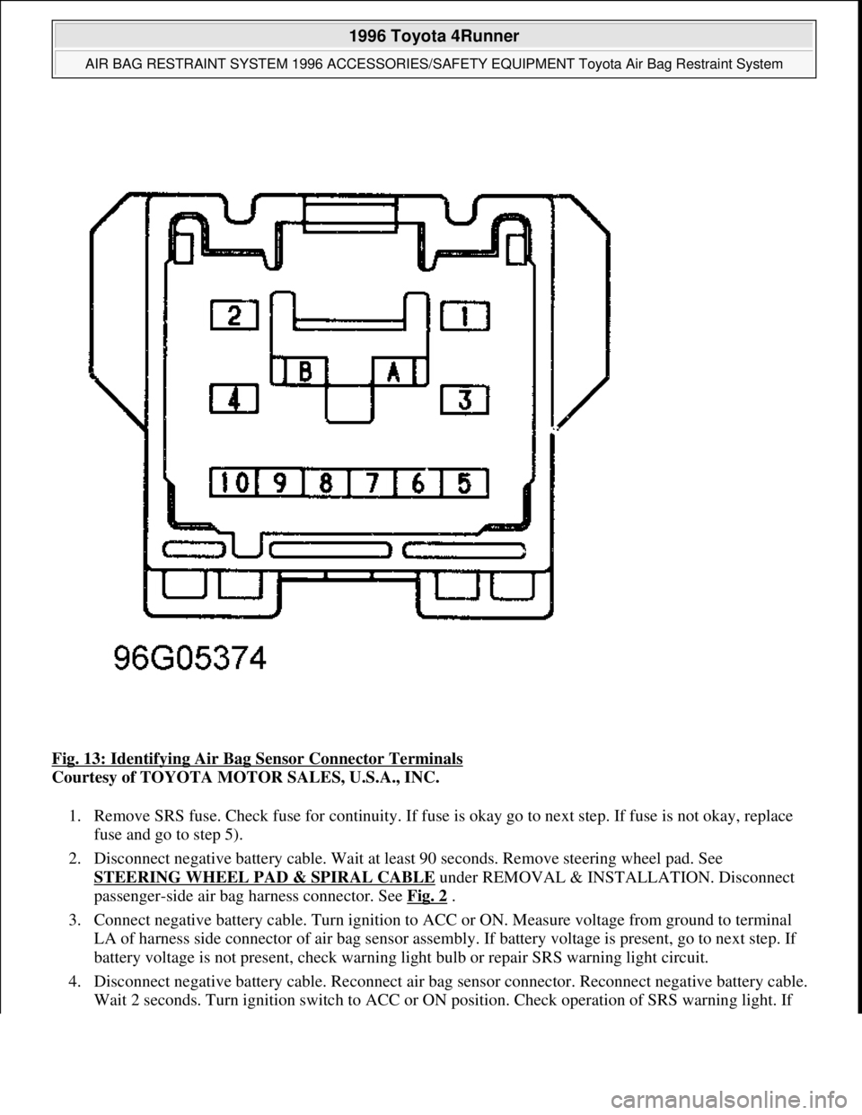
Fig. 13: Identifying Air Bag Sensor Connector Terminals
Courtesy of TOYOTA MOTOR SALES, U.S.A., INC.
1. Remove SRS fuse. Check fuse for continuity. If fuse is okay go to next step. If fuse is not okay, replace
fuse and go to step 5).
2. Disconnect negative battery cable. Wait at least 90 seconds. Remove steering wheel pad. See
STEERING WHEEL PAD & SPIRAL CABLE
under REMOVAL & INSTALLATION. Disconnect
passenger-side air bag harness connector. See Fig. 2
.
3. Connect negative battery cable. Turn ignition to ACC or ON. Measure voltage from ground to terminal
LA of harness side connector of air bag sensor assembly. If battery voltage is present, go to next step. If
battery voltage is not present, check warning light bulb or repair SRS warning light circuit.
4. Disconnect negative battery cable. Reconnect air bag sensor connector. Reconnect negative battery cable.
Wait 2 seconds. Turn i
gnition switch to ACC or ON position. Check operation of SRS warning light. If
1996 Toyota 4Runner
AIR BAG RESTRAINT SYSTEM 1996 ACCESSORIES/SAFETY EQUIPMENT Toyota Air Bag Restraint System
Microsoft
Tuesday, August 18, 2009 7:33:32 PMPage 18 © 2005 Mitchell Repair Information Company, LLC.
Page 53 of 1632
light is okay, the malfunction is now corrected. If light is not okay, check terminal LA of air bag sensor
assembly. If terminal is okay, replace air bag sensor assembly.
5. If new fuse burns out again, check harness between SRS fuse and SRS warning light. If fuse is not burned
out check for intermittent fault. See AIR BAG WARNING LIGHT INTERMITTENT
under
DIAGNOSIS.
AIR BAG WARNING LIGHT STAYS ON WITH IGNITION OFF
Disable SRS. See DISABLING & ACTIVATING AIR BAG SYSTEM
. Disconnect air bag sensor connector
(s). Reconnect negative battery cable. If air bag warning light is off, replace air bag sensor. If air bag warning
light is still on, repair warning light circuit or AB circuit leading to DLC. See Fig. 12
.
AIR BAG WARNING LIGHT INTERMITTENT
If air bag warning light comes on intermittently, perform the following tests to simulate driving conditions:
Wiggle-test wiring harness.
Using a hair dryer, apply heat to components.
Spray water onto entire vehicle (not directly onto electrical components) to simulate humidity.
If problem cannot be found, replace all components including wiring harness.
CODE(S) NOT DISPLAYED
1. Turn ignition switch from LOCK to ACC or ON position. If air bag warning light does not come on,
repair air bag warning light circuit. If air bag warning light comes on, go to next step.
2. Turn ignition to ACC or ON. Measure voltage between terminals Tc and E1 of DLC. See Fig. 12
. If
battery voltage is present, go to step 4). If battery voltage is not present go to next step.
3. Measure voltage between body ground and terminal Tc of DLC. If battery voltage is present, repair
harness between body ground and terminal E1 of DLC. If battery voltage is not present, go to next step.
4. Turn ignition to LOCK. Disconnect negative battery cable. wait at least 90 seconds. Disconnect air bag
sensor assembly connector. Connect a jumper wire between body ground and terminal Tc from back side.
See Fig. 13
. If air bag warning light does not come on, replace air bag sensor. If air bag warning light
comes on, check wiring harness between air bag sensor and DLC.
CODE(S) CONTINUOUSLY DISPLAYED
Disable SRS. See DISABLING & ACTIVATING AIR BAG SYSTEM
. Disconnect air bag sensor connector
NOTE: Use the following procedure if code(s) are not displayed or air bag warning light
stays on when jumper wire is connected between terminals Tc and E1 of DLC
connector.
NOTE: Use the following procedure if code(s) are displayed without connecting jumper
wire between terminals Tc and E1 of DLC connector.
1996 Toyota 4Runner
AIR BAG RESTRAINT SYSTEM 1996 ACCESSORIES/SAFETY EQUIPMENT Toyota Air Bag Restraint System
Microsoft
Tuesday, August 18, 2009 7:33:32 PMPage 19 © 2005 Mitchell Repair Information Company, LLC.
Page 60 of 1632
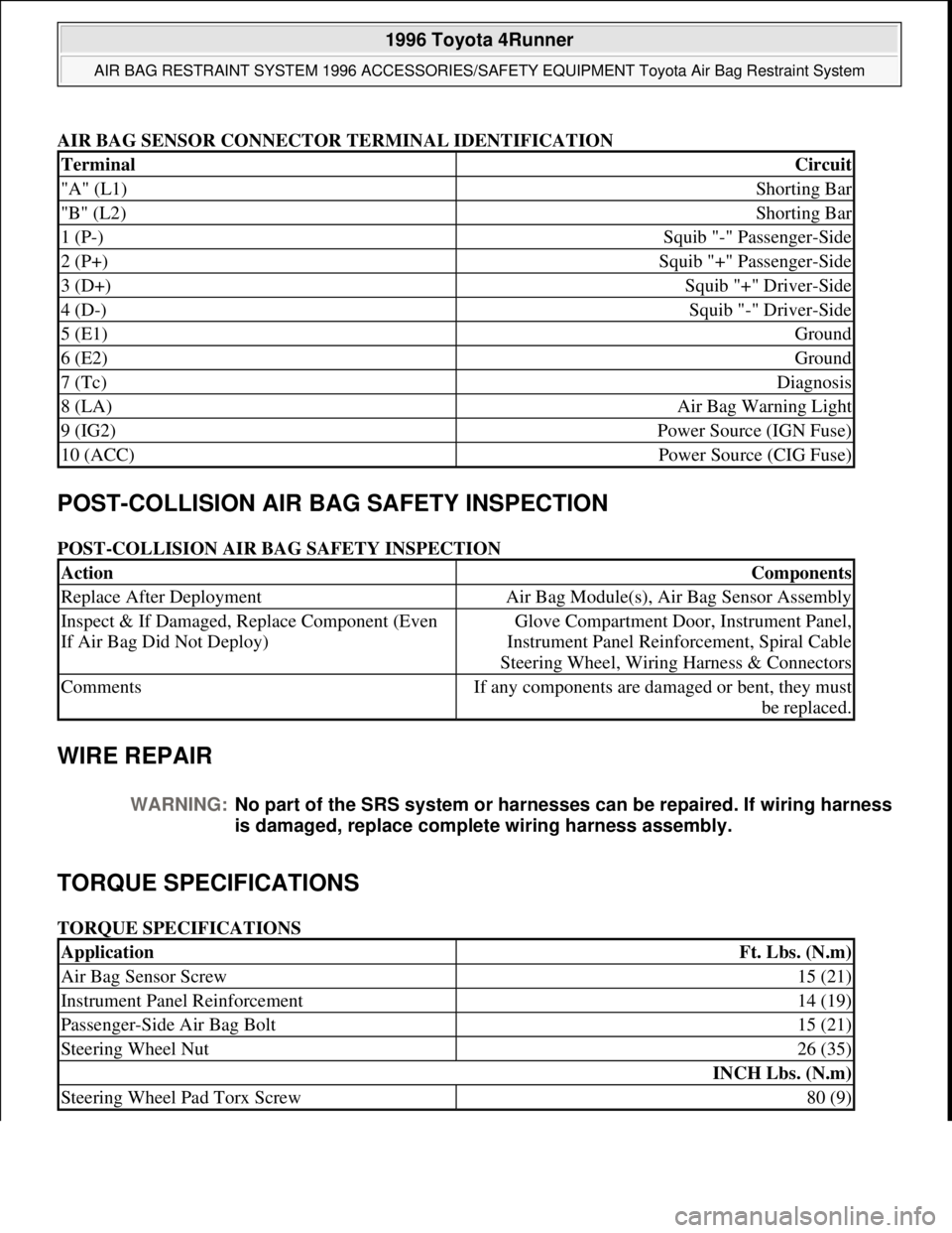
AIR BAG SENSOR CONNECTOR TERMINAL IDENTIFICATION
POST-COLLISION AIR BAG SAFETY INSPECTION
POST-COLLISION AIR BAG SAFETY INSPECTION
WIRE REPAIR
TORQUE SPECIFICATIONS
TORQUE SPECIFICATIONS
TerminalCircuit
"A" (L1)Shorting Bar
"B" (L2)Shorting Bar
1 (P-)Squib "-" Passenger-Side
2 (P+)Squib "+" Passenger-Side
3 (D+)Squib "+" Driver-Side
4 (D-)Squib "-" Driver-Side
5 (E1)Ground
6 (E2)Ground
7 (Tc)Diagnosis
8 (LA)Air Bag Warning Light
9 (IG2)Power Source (IGN Fuse)
10 (ACC)Power Source (CIG Fuse)
ActionComponents
Replace After DeploymentAir Bag Module(s), Air Bag Sensor Assembly
Inspect & If Damaged, Replace Component (Even
If Air Bag Did Not Deploy)Glove Compartment Door, Instrument Panel,
Instrument Panel Reinforcement, Spiral Cable
Steering Wheel, Wiring Harness & Connectors
CommentsIf any components are damaged or bent, they must
be replaced.
WARNING:No part of the SRS system or harnesses can be repaired. If wiring harness
is damaged, replace complete wiring harness assembly.
ApplicationFt. Lbs. (N.m)
Air Bag Sensor Screw15 (21)
Instrument Panel Reinforcement14 (19)
Passenger-Side Air Bag Bolt15 (21)
Steering Wheel Nut26 (35)
INCH Lbs. (N.m)
Steering Wheel Pad Torx Screw80 (9)
1996 Toyota 4Runner
AIR BAG RESTRAINT SYSTEM 1996 ACCESSORIES/SAFETY EQUIPMENT Toyota Air Bag Restraint System
Microsoft
Tuesday, August 18, 2009 7:33:32 PMPage 26 © 2005 Mitchell Repair Information Company, LLC.