brake sensor TOYOTA RAV4 1996 Service Service Manual
[x] Cancel search | Manufacturer: TOYOTA, Model Year: 1996, Model line: RAV4, Model: TOYOTA RAV4 1996Pages: 1632, PDF Size: 41.64 MB
Page 1087 of 1632
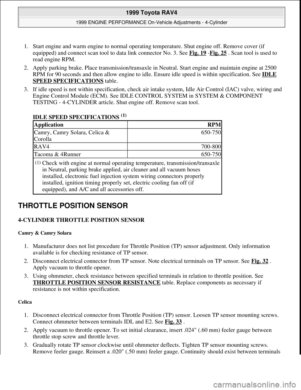
1. Start engine and warm engine to normal operating temperature. Shut engine off. Remove cover (if
equipped) and connect scan tool to data link connector No. 3. See Fig. 19
-Fig. 25 . Scan tool is used to
read engine RPM.
2. Apply parking brake. Place transmission/transaxle in Neutral. Start engine and maintain engine at 2500
RPM for 90 seconds and then allow engine to idle. Ensure idle speed is within specification. See IDLE
SPEED SPECIFICATIONS table.
3. If idle speed is not within specification, check air intake system, Idle Air Control (IAC) valve, wiring and
Engine Control Module (ECM). See IDLE CONTROL SYSTEM in SYSTEM & COMPONENT
TESTING - 4-CYLINDER article. Shut engine off. Remove scan tool.
IDLE SPEED SPECIFICATIONS
(1)
THROTTLE POSITION SENSOR
4-CYLINDER THROTTLE POSITION SENSOR
Camry & Camry Solara
1. Manufacturer does not list procedure for Throttle Position (TP) sensor adjustment. Only information
available is for checking resistance of TP sensor.
2. Disconnect electrical connector from TP sensor. Note electrical terminals on TP sensor. See Fig. 32
.
Apply vacuum to throttle opener.
3. Using ohmmeter, check resistance between specified terminals in relation to throttle position. See
THROTTLE POSITION SENSOR RESISTANCE
table. Replace components as necessary if
resistance is not within specification.
Celica
1. Disconnect electrical connector from Throttle Position (TP) sensor. Loosen TP sensor mounting screws.
Connect ohmmeter between terminals IDL and E2. See Fig. 33
.
2. Apply vacuum to throttle opener. To set initial clearance, insert .024" (.60 mm) feeler gauge between
throttle stop screw and throttle lever.
3. Gradually rotate TP sensor clockwise until ohmmeter deflects. Tighten TP sensor mounting screws.
Remove feeler
gauge. Reinsert a .020" (.50 mm) feeler gauge. Continuity should exist between terminals
ApplicationRPM
Camry, Camry Solara, Celica &
Corolla650-750
RAV4700-800
Tacoma & 4Runner650-750
(1)Check with engine at normal operating temperature, transmission/transaxle
in Neutral, parking brake applied, air cleaner and all vacuum hoses
installed, electronic fuel injection system wiring connectors properly
installed, ignition timing properly set, electric cooling fan off (if
equipped), and A/C and all accessories off.
1999 Toyota RAV4
1999 ENGINE PERFORMANCE On-Vehicle Adjustments - 4-Cylinder
Microsoft
Sunday, November 22, 2009 10:25:31 AMPage 36 © 2005 Mitchell Repair Information Company, LLC.
Page 1143 of 1632
WHEEL BEARING INSPECTION
Raise and support vehicle. Remove wheel and brake drum, or rotor (if equipped). Position dial indicator with
stem against center of axle hub. Move axle hub in and out while observing dial indicator. Replace hub if axial
play exceeds .002" (.05 mm). Measure hub axial runout. Replace hub if runout exceeds .0028" (.07 mm).
WHEEL BEARING ADJUSTMENT
Hubs must be replaced if axle end play or runout are not within specification. No adjustment is available. See
WHEEL BEARINGS (HUBS)
under REMOVAL & INSTALLATION
REMOVAL & INSTALLATION
AXLE BEAM
Removal (ECHO)
1. Raise and support vehicle. Remove rear wheels and brake drums. Disconnect brakelines from flex hoses,
remove retaining clips from shock absorbers and plug openings. Disconnect ABS sensor and remove
harness clamp from axle beam. Disconnect parking brake cable from backing plate and remove cable
clamp from axle beam. Remove axle hub assemblies. Remove backing plate assemblies, with brake shoes
still attached.
2. Remove high-mounted stop light from rear package tray. Remove 2 clips and remove package tray.
Remove rear seat. Remove door scuff plate and door opening trim. See Fig. 5
. Remove rear seat outer
seat belts and remove quarter trim panels. On 2 door models, remove outer anchor for front seat shoulder
belt and remove roof side inner garnish. On all models, remove room partition board.
3. Using 2 floor jacks, support rear axle beam under each coil spring. While holding shock absorber shaft,
remove the 2 upper nuts, disconnecting lower suspension supports from body. Lower jacks slowly.
Remove coil springs and insulators. Remove axle beam-to-
body bolts. Remove axle beam. NOTE: See SPECIFICATIONS & PROCEDURES
in WHEEL ALIGNMENT article.
1999 Toyota RAV4
1999-2000 SUSPENSION Rear - Front Wheel Drive
Microsoft
Sunday, November 22, 2009 10:37:21 AMPage 5 © 2005 Mitchell Repair Information Company, LLC.
Page 1144 of 1632
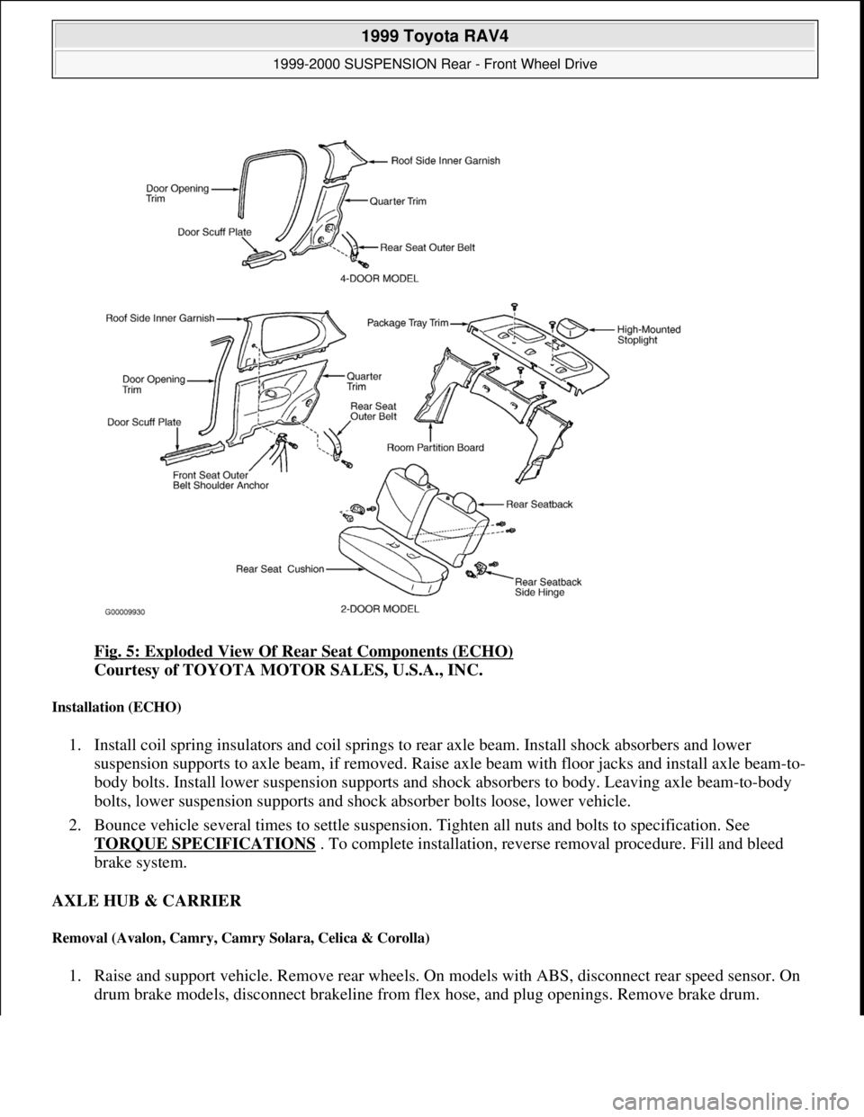
Fig. 5: Exploded View Of Rear Seat Components (ECHO)
Courtesy of TOYOTA MOTOR SALES, U.S.A., INC.
Installation (ECHO)
1. Install coil spring insulators and coil springs to rear axle beam. Install shock absorbers and lower
suspension supports to axle beam, if removed. Raise axle beam with floor jacks and install axle beam-to-
body bolts. Install lower suspension supports and shock absorbers to body. Leaving axle beam-to-body
bolts, lower suspension supports and shock absorber bolts loose, lower vehicle.
2. Bounce vehicle several times to settle suspension. Tighten all nuts and bolts to specification. See
TORQUE SPECIFICATIONS
. To complete installation, reverse removal procedure. Fill and bleed
brake system.
AXLE HUB & CARRIER
Removal (Avalon, Camry, Camry Solara, Celica & Corolla)
1. Raise and support vehicle. Remove rear wheels. On models with ABS, disconnect rear speed sensor. On
drum brake models, disconnect brakeline from flex hose, and plu
g openings. Remove brake drum.
1999 Toyota RAV4
1999-2000 SUSPENSION Rear - Front Wheel Drive
Microsoft
Sunday, November 22, 2009 10:37:21 AMPage 6 © 2005 Mitchell Repair Information Company, LLC.
Page 1145 of 1632
2. On disc brake models, remove rotor and caliper. Leaving flex hose attached, suspend caliper aside. On all
models, remove 4 axle hub-to-axle carrier bolts, axle hub and "O" ring.
3. Note position of nuts on suspension arms and strut rods for installation reference. Disconnect strut rod
from axle carrier. Disconnect No. 1 and No. 2 lower suspension arms from axle carrier. Remove 2 bolts
and nuts, and remove axle carrier.
Installation (Avalon, Camry, Camry Solara, Celica & Corolla)
To install, reverse removal procedure. Coat NEW "O" ring with grease and install hub. Tighten all fasteners to
specification. See TORQUE SPECIFICATIONS
. Bleed brake system. Check rear wheel alignment.
Removal (RAV4)
1. Raise and support vehicle. Remove rear wheel and brake drum. On 4WD models, remove drive axle.
Remove ABS speed sensor (if equipped). Remove drive axle lock nut. Place matchmarks on drive axle
and differential gear shaft. Remove the 4 nuts and remove drive axle from differential side gear. On FWD
models, disconnect ABS sensor and remove harness clamp (if equipped). On all models, remove 2
brakeline clamps from rear No. 1 suspension arm. Remove parking brake cable clamp. See Fig. 4
.
2. Remove 4 bolts and remove axle hub and backing plate, leaving brake shoes attached. Disconnect lower
end of shock absorber. Using Ball Joint Puller (09628-62011), disconnect upper and lower suspension
arms from rear No. 1 suspension arm. Place matchmarks on camber adjusting cam and suspension
member and remove bolt. See Fig. 6
. Place matchmarks on toe adjusting cam and body and loosen bolt.
See Fig. 7
. Remove coil spring and upper insulator. Remove loosened toe adjusting cam bolt. Remove
rear No. 1 suspension arm. NOTE: Bounce vehicle several times to stabilize suspension. Tighten axle carrier-to-
shock absorber assembly and suspension arm bolts to specification with
vehicle at normal operating height.
1999 Toyota RAV4
1999-2000 SUSPENSION Rear - Front Wheel Drive
Microsoft
Sunday, November 22, 2009 10:37:21 AMPage 7 © 2005 Mitchell Repair Information Company, LLC.
Page 1149 of 1632
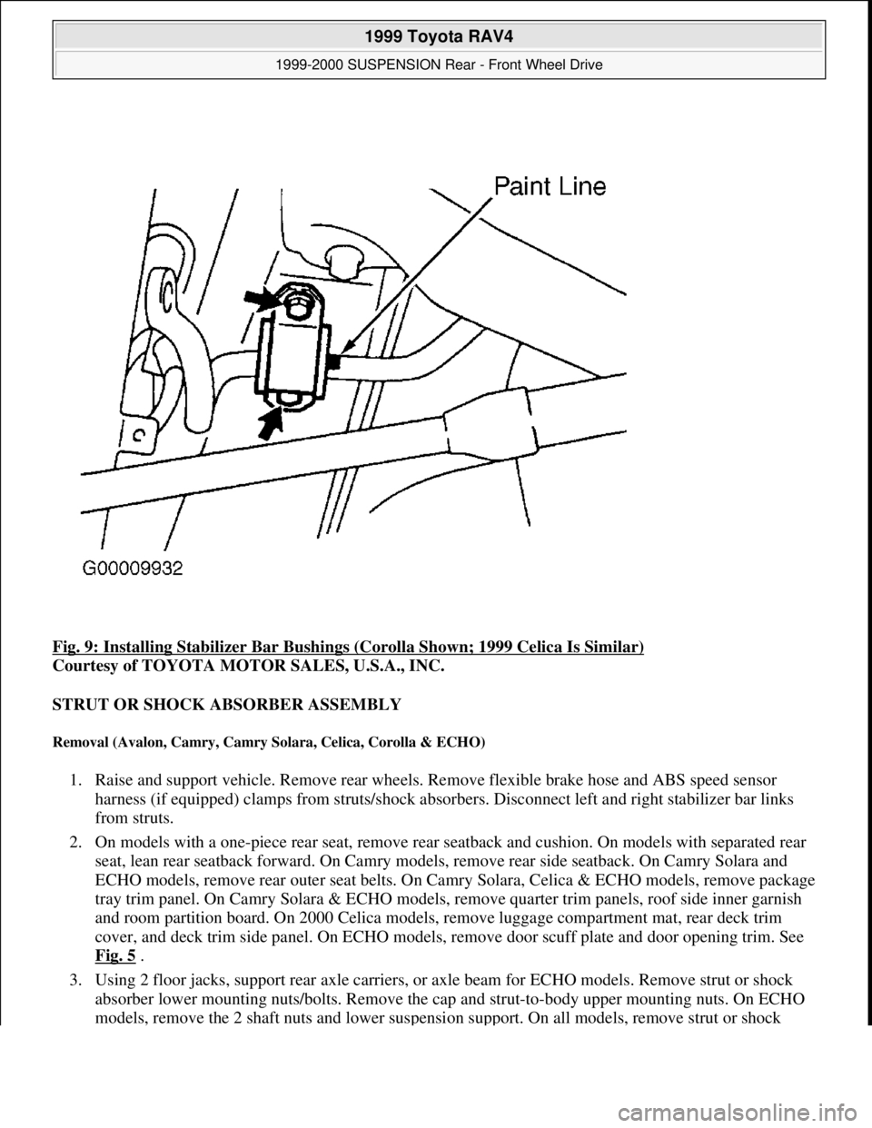
Fig. 9: Installing Stabilizer Bar Bushings (Corolla Shown; 1999 Celica Is Similar)
Courtesy of TOYOTA MOTOR SALES, U.S.A., INC.
STRUT OR SHOCK ABSORBER ASSEMBLY
Removal (Avalon, Camry, Camry Solara, Celica, Corolla & ECHO)
1. Raise and support vehicle. Remove rear wheels. Remove flexible brake hose and ABS speed sensor
harness (if equipped) clamps from struts/shock absorbers. Disconnect left and right stabilizer bar links
from struts.
2. On models with a one-piece rear seat, remove rear seatback and cushion. On models with separated rear
seat, lean rear seatback forward. On Camry models, remove rear side seatback. On Camry Solara and
ECHO models, remove rear outer seat belts. On Camry Solara, Celica & ECHO models, remove package
tray trim panel. On Camry Solara & ECHO models, remove quarter trim panels, roof side inner garnish
and room partition board. On 2000 Celica models, remove luggage compartment mat, rear deck trim
cover, and deck trim side panel. On ECHO models, remove door scuff plate and door opening trim. See
Fig. 5
.
3. Using 2 floor jacks, support rear axle carriers, or axle beam for ECHO models. Remove strut or shock
absorber lower mounting nuts/bolts. Remove the cap and strut-to-body upper mounting nuts. On ECHO
models, remove the 2 shaft nuts and lower suspension support. On all models, remove strut or shock
1999 Toyota RAV4
1999-2000 SUSPENSION Rear - Front Wheel Drive
Microsoft
Sunday, November 22, 2009 10:37:21 AMPage 11 © 2005 Mitchell Repair Information Company, LLC.
Page 1151 of 1632
2. Using a floor jack, support suspension member. Remove suspension member nuts, bolts and stoppers.
Lower suspension member. Remove No. 1 lower suspension arm.
Installation
1. To install, reverse removal procedure. Be sure to install components in their original locations. On all
models except Corolla, suspension arms are marked with paint. Install suspension arms with paint marks
facing rearward. On Corolla models, suspension arms have left hand threads on one side. Install
suspension arms with left hand threads to the axle carrier side.
2. Install all nuts and bolts, but DO NOT tighten. Install wheels. Lower vehicle. Bounce vehicle several
times to stabilize suspension. Tighten all nuts and bolts to specification, with vehicle weight on
suspension. See TORQUE SPECIFICATIONS
. Check rear wheel alignment. See SPECIFICATIONS
& PROCEDURES article in WHEEL ALIGNMENT.
WHEEL BEARINGS (HUBS)
Removal (Avalon, Camry, Camry Solara, Celica, Corolla & RAV4 FWD)
1. Raise and support vehicle. Remove rear wheels. On drum brake models, remove brake drum. On disc
brake models, remove rotor. Remove caliper, leaving flex hose attached, suspend aside. Disconnect ABS
sensor (if equipped).
2. On all models, check wheel hub axial play and runout. See WHEEL BEARING INSPECTION
under
ADJUSTMENTS & INSPECTION. Remove 4 bolts and remove axle hub and "O" ring.
Installation
Coat NEW "O" ring with grease and install hub. To complete installation, reverse removal procedure. Tighten
all nuts and bolts to specification. See TORQUE SPECIFICATIONS
.
Removal (RAV4 4WD)
1. Raise and support vehicle. Remove rear wheel and brake drum. Using a dial indicator, check wheel
bearing end play and runout. End play should not exceed .002" (.05 mm). Runout should not
exceed .0028" (.07 mm). If axle hub end play or runout exceed specification, replace hub with bearing.
2. Remove bolt and ABS sensor. Remove drive axle. Remove drive axle lock nut. Place matchmarks on
drive axle and differential side gear shaft. Remove 4 nuts and remove drive axle. Disassemble rear brake
shoes. Disconnect brakeline from wheel cylinder. Remove parking brake cable. Remove 4 bolts and
remove axle hub with bearing and backing plate. See Fig. 10
.
3. Using Puller (09950-40011) and Replacer Set (09950-60011), remove bearing from axle hub. Remove
bearing race from axle hub. See Fig. 11. NOTE: Wheel bearings and wheel hub, is a one piece assembly and must be replaced
as a single unit.
1999 Toyota RAV4
1999-2000 SUSPENSION Rear - Front Wheel Drive
Microsoft
Sunday, November 22, 2009 10:37:21 AMPage 13 © 2005 Mitchell Repair Information Company, LLC.