battery location TOYOTA RAV4 1996 Service Repair Manual
[x] Cancel search | Manufacturer: TOYOTA, Model Year: 1996, Model line: RAV4, Model: TOYOTA RAV4 1996Pages: 1632, PDF Size: 41.64 MB
Page 142 of 1632
1. Before installing transmission, use dial indicator to check drive plate runout. Drive plate runout should be
checked right next to the starter ring gear on the drive plate. Replace drive plate if runout
exceeds .0079" (.200 mm).
2. Install torque converter on transmission. To ensure torque converter is fully seated, torque converter
depth should be checked. Using straightedge and caliper, measure torque converter depth from torque
converter bolt lug on torque converter to the surface on transmission. See Fig. 1
.
3. Torque converter depth should be more than .707" (17.95 mm). If torque converter depth is less than
specified, check for improperly seated torque converter.
4. To install, reverse removal procedure. Tighten all bolts/nuts to specification. See TORQUE
SPECIFICATIONS . When installing torque converter bolts, apply Loctite to torque converter bolt
threads before installing.
5. Apply grease to transfer case shift lever before installing. Use NEW gasket when installing front exhaust
pipe. Adjust all cables, shift linkages and fill with ATF. See appropriate TRANSMISSION SERVICING
article.
Removal (4Runner 2WD)
1. Disconnect negative battery cable. Remove transmission oil dipstick, dipstick tube and "O" ring.
Disconnect throttle valve cable from throttle body.
2. Raise and support vehicle. Remove lower engine cover. Disconnect shift linkage for transmission at
gearshift. Remove front exhaust pipe, located between exhaust manifold and catalytic converter on rear
exhaust pipe.
3. Place reference marks on drive shaft flange for reassembly reference. Remove drive shaft. Disconnect
necessary electrical connectors for transmission removal. Remove transmission oil cooler pipes and
brackets as necessary.
4. Support transmission with floor jack. Remove transmission crossmember, located below transmission.
Remove starter.
5. Remove cover from front of transmission for access to torque converter bolts. On 3.4L, note location of
Green torque converter bolt for reassembly reference. Remove torque converter bolts. Remove
transmission-to-cylinder block bolts. Lower transmission from vehicle.
Installation
1. Before installing transmission, use dial indicator to check drive plate runout. Drive plate runout should be
checked right next to the starter ring gear on the drive plate. Replace drive plate if runout
exceeds .0079" (.200 mm).
2. Install torque converter on transmission. To ensure torque converter is fully seated, torque converter
depth should be checked. Using straightedge and caliper, measure torque converter depth from torque
converter bolt lug on torque converter to the surface on transmission. See Fig. 1
.
3. Torque converter depth should be more than 1.250" (31.75 mm) for 2.7L 4-cylinder or .707" (17.95 mm)
for 3.4L V6. If torque converter depth is less than specified, check for improperly seated torque converter.
4. To install, reverse removal procedure. Tighten all bolts/nuts to specification. See TORQUE
SPECIFICATIONS . When installing torque converter bolts, apply Loctite to torque converter bolt
threads before installin
g. On 3.4L V6, ensure the Green torque converter bolt is installed first before
1998 Toyota Avalon XLS
TRANSMISSION SERVICING - A/T 1997-98 TRANSMISSION SERVICING Toyota - Transmission Removal &
Installation
Helpmelearn
November-03-08 10:30:29 AMPage 30 © 2005 Mitchell Repair Information Company, LLC.
Page 143 of 1632
installing the remaining torque converter bolts.
5. Use NEW gasket when installing front exhaust pipe. Adjust all cables, shift linkages and fill with ATF.
See appropriate TRANSMISSION SERVICING article.
Removal (4Runner 4WD)
1. Disconnect negative battery cable. Remove rear console upper panel and disconnect electrical connectors.
Rear console upper panel is located on the top of the console, near emergency brake lever.
2. Remove heater control knobs from instrument panel. Using screwdriver, pry heater control plate from
center finish panel on instrument panel. Center finish panel is the panel that fits around the radio and air
outlet ducts, located at center of instrument panel.
3. Remove screws and disconnect electrical connectors from center finish panel from instrument panel.
Remove center finish panel.
4. On models without 2-4 selector button on side of transfer case shift lever, unscrew knob from transfer
case shift lever. On models with2-4 selector button on side of transfer case shift lever, remove screw from
knob on transfer case shift lever. Remove knob from transfer case shift lever and lay aside with wire
attached.
5. On all models, remove upper console panel which contains boot for transfer case shift lever and is located
on center console. On models with 2-4 selector button on side of transfer case shift lever, disconnect
electrical connector for 2-4 selector button and remove knob on transfer case shift lever.
6. On all models, remove screws, clips and front console box, located around transmission shift lever
assembly and transfer case shift lever. Raise and support vehicle. Disconnect shift linkage at transmission
shift lever.
7. Disconnect electrical connectors for removal of transmission shift lever assembly. Remove transmission
shift lever assembly. Remove snap ring and transfer case shift lever.
8. Remove transmission oil dipstick, dipstick tube and "O" ring. Remove lower engine covers. Place
reference marks on drive shaft flanges for reassembly reference. Remove drive shafts.
9. Remove front exhaust pipe, located between exhaust manifold and catalytic converter on rear exhaust
pipe. Disconnect and necessary electrical connectors for transmission and transfer case removal. Separate
wiring harness from transmission and transfer case.
10. Remove starter. Remove transmission oil cooler pipes and brackets as necessary. On 3.4L V6, it may be
necessary to remove stabilizer bar.
11. On all models, support transmission with floor jack. Remove rear transmission mount-to-transmission
crossmember bolts. Remove transmission crossmember, located below transmission and transfer case.
12. Remove torque converter cover from front of transmission. On 3.4L, note location of Green torque
converter bolt for re-installation reference. Remove torque converter bolts. Remove transmission-to-
cylinder block bolts. Lower transmission with transfer case from vehicle.
Installation
1. Before installing transmission, use dial indicator to check drive plate runout. Drive plate runout should be
checked right next to the starter ring gear on the drive plate. Replace drive plate if runout
exceeds .0079" (.200 mm).
2. Install torque converter on transmission. To ensure torque converter is fully seated, torque converter
1998 Toyota Avalon XLS
TRANSMISSION SERVICING - A/T 1997-98 TRANSMISSION SERVICING Toyota - Transmission Removal &
Installation
Helpmelearn
November-03-08 10:30:29 AMPage 31 © 2005 Mitchell Repair Information Company, LLC.
Page 471 of 1632
1999-2000 ENGINE COOLING
Electric Cooling Fans
IDENTIFICATION
ELECTRIC COOLING FAN IDENTIFICATION
DESCRIPTION & OPERATION
Land Cruiser, Tacoma, Tundra and 4Runner use a belt-driven cooling fan attached to the water pump. All other
models use 2 electric cooling fans located directly behind the radiator. Fans are controlled via Engine Coolant
Temperature (ECT) switches/sensors, and turn on when engine coolant temperature is above 208°F (98°C) on
Avalon, Camry with 3.0L, Camry Solara with 3.0L and Sienna. On Camry with 2.2L, Camry Solara with 2.2L,
Celica, Corolla, ECHO, MR2 and RAV4, ECT turns cooling fans on above 199°F (93°C). On Avalon, Camry
with 3.0L, Camry Solara with 3.0L and Sienna, fans will turn off when engine coolant temperature falls below
190°F (88°C). On Camry with 2.2L, Camry Solara with 2.2L, Celica, Corolla and RAV4, fans will turn off
below 181°F (83°C).
SYSTEM TESTS
ELECTRIC COOLING FAN
Avalon (1999), Camry 3.0L, Camry Solara 3.0L & Sienna
1. With engine coolant temperature below 190°F (88°C), turn ignition switch to ON position (engine off).
Ensure fans stop.
2. If fan do not stop, test cooling fan relay and ECT switch. See COOLING FAN RELAYS
and ECT
SWITCH . Check for loose or broken connector or wiring between relay and ECT switch. Repair as
necessary.
3. Disconnect No. 1 ECT switch connector. See ECT SWITCH LOCATIONS
table. With ignition still in
ON position, ensure cooling fan turns on. If not, check fuses, engine main relay, cooling fan relay and
cooling fan motor. Check for short between cooling fan relay and ECT switch.
4. Start engine and raise temperature above 208°F (98°C). Ensure cooling fan turns. If not, replace No. 1
ECT switch.
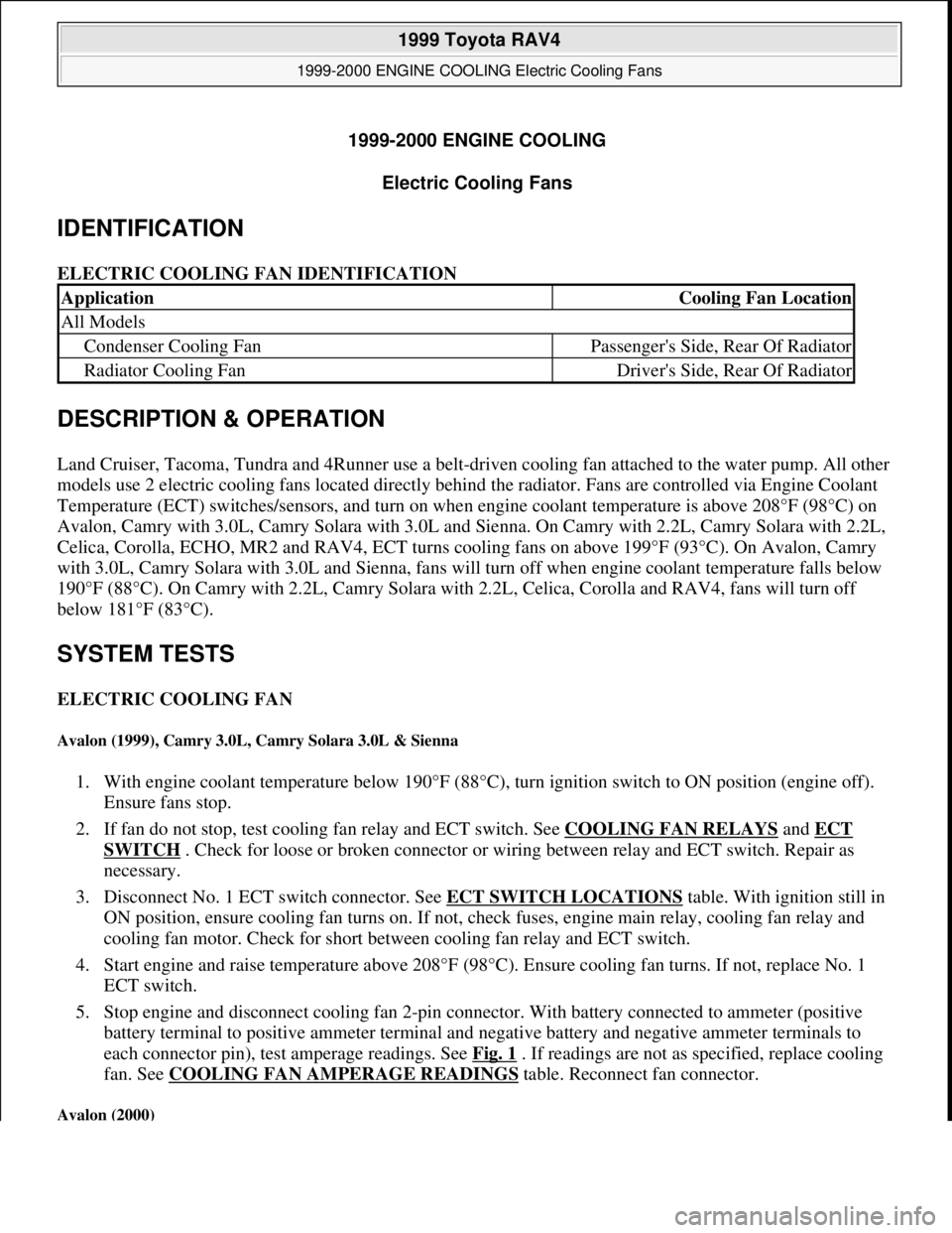
5. Stop engine and disconnect cooling fan 2-pin connector. With battery connected to ammeter (positive
battery terminal to positive ammeter terminal and negative battery and negative ammeter terminals to
each connector pin), test amperage readings. See Fig. 1
. If readings are not as specified, replace cooling
fan. See COOLING FAN AMPERAGE READINGS
table. Reconnect fan connector.
Avalon (2000)
ApplicationCooling Fan Location
All Models
Condenser Cooling FanPassenger's Side, Rear Of Radiator
Radiator Cooling FanDriver's Side, Rear Of Radiator
1999 Toyota RAV4
1999-2000 ENGINE COOLING Electric Cooling Fans
1999 Toyota RAV4
1999-2000 ENGINE COOLING Electric Cooling Fans
Microsoft
Sunday, November 22, 2009 10:21:41 AMPage 1 © 2005 Mitchell Repair Information Company, LLC.
Microsoft
Sunday, November 22, 2009 10:21:45 AMPage 1 © 2005 Mitchell Repair Information Company, LLC.
Page 474 of 1632
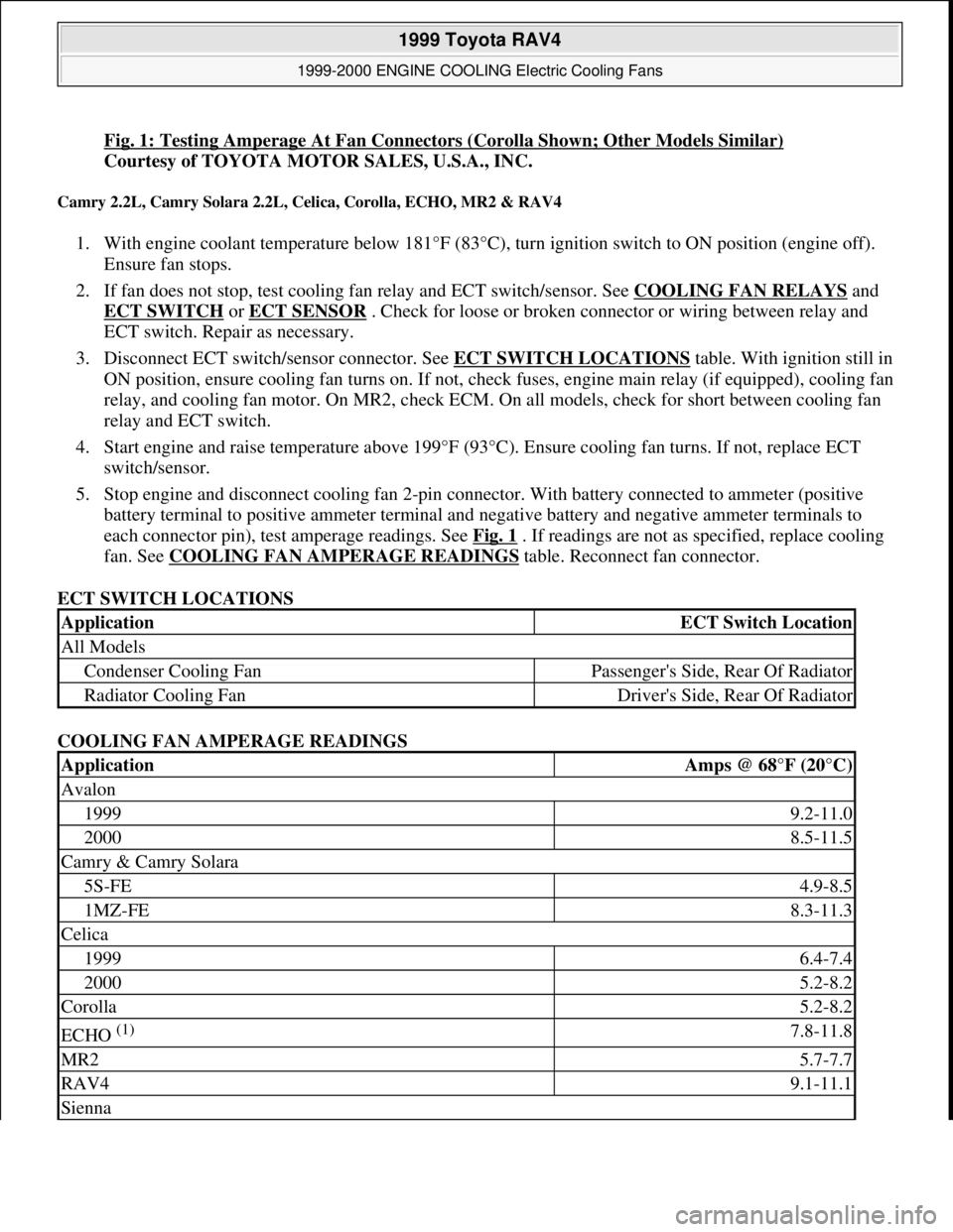
Fig. 1: Testing Amperage At Fan Connectors (Corolla Shown; Other Models Similar)
Courtesy of TOYOTA MOTOR SALES, U.S.A., INC.
Camry 2.2L, Camry Solara 2.2L, Celica, Corolla, ECHO, MR2 & RAV4
1. With engine coolant temperature below 181°F (83°C), turn ignition switch to ON position (engine off).
Ensure fan stops.
2. If fan does not stop, test cooling fan relay and ECT switch/sensor. See COOLING FAN RELAYS
and
ECT SWITCH
or ECT SENSOR . Check for loose or broken connector or wiring between relay and
ECT switch. Repair as necessary.
3. Disconnect ECT switch/sensor connector. See ECT SWITCH LOCATIONS
table. With ignition still in
ON position, ensure cooling fan turns on. If not, check fuses, engine main relay (if equipped), cooling fan
relay, and cooling fan motor. On MR2, check ECM. On all models, check for short between cooling fan
relay and ECT switch.
4. Start engine and raise temperature above 199°F (93°C). Ensure cooling fan turns. If not, replace ECT
switch/sensor.
5. Stop engine and disconnect cooling fan 2-pin connector. With battery connected to ammeter (positive
battery terminal to positive ammeter terminal and negative battery and negative ammeter terminals to
each connector pin), test amperage readings. See Fig. 1
. If readings are not as specified, replace cooling
fan. See COOLING FAN AMPERAGE READINGS
table. Reconnect fan connector.
ECT SWITCH LOCATIONS
COOLING FAN AMPERAGE READINGS
ApplicationECT Switch Location
All Models
Condenser Cooling FanPassenger's Side, Rear Of Radiator
Radiator Cooling FanDriver's Side, Rear Of Radiator
ApplicationAmps @ 68°F (20°C)
Avalon
19999.2-11.0
20008.5-11.5
Camry & Camry Solara
5S-FE4.9-8.5
1MZ-FE8.3-11.3
Celica
19996.4-7.4
20005.2-8.2
Corolla5.2-8.2
ECHO (1) 7.8-11.8
MR25.7-7.7
RAV49.1-11.1
Sienna
1999 Toyota RAV4
1999-2000 ENGINE COOLING Electric Cooling Fans
Microsoft
Sunday, November 22, 2009 10:21:41 AMPage 4 © 2005 Mitchell Repair Information Company, LLC.
Page 674 of 1632
1999 TOYOTA
RAV4
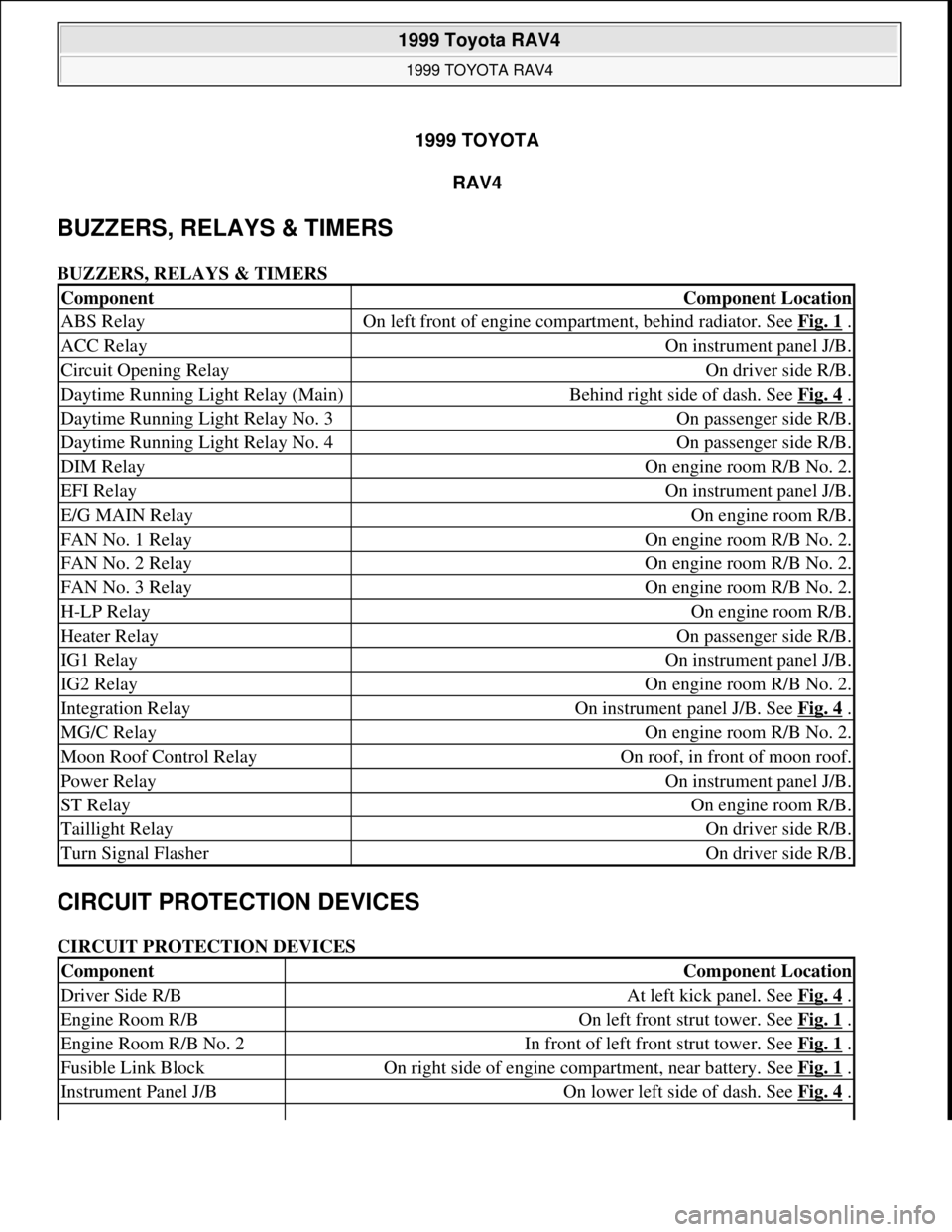
BUZZERS, RELAYS & TIMERS
BUZZERS, RELAYS & TIMERS
CIRCUIT PROTECTION DEVICES
CIRCUIT PROTECTION DEVICES
ComponentComponent Location
ABS RelayOn left front of engine compartment, behind radiator. See Fig. 1 .
ACC RelayOn instrument panel J/B.
Circuit Opening RelayOn driver side R/B.
Daytime Running Light Relay (Main)Behind right side of dash. See Fig. 4 .
Daytime Running Light Relay No. 3On passenger side R/B.
Daytime Running Light Relay No. 4On passenger side R/B.
DIM RelayOn engine room R/B No. 2.
EFI RelayOn instrument panel J/B.
E/G MAIN RelayOn engine room R/B.
FAN No. 1 RelayOn engine room R/B No. 2.
FAN No. 2 RelayOn engine room R/B No. 2.
FAN No. 3 RelayOn engine room R/B No. 2.
H-LP RelayOn engine room R/B.
Heater RelayOn passenger side R/B.
IG1 RelayOn instrument panel J/B.
IG2 RelayOn engine room R/B No. 2.
Integration RelayOn instrument panel J/B. See Fig. 4 .
MG/C RelayOn engine room R/B No. 2.
Moon Roof Control RelayOn roof, in front of moon roof.
Power RelayOn instrument panel J/B.
ST RelayOn engine room R/B.
Taillight RelayOn driver side R/B.
Turn Signal FlasherOn driver side R/B.
ComponentComponent Location
Driver Side R/BAt left kick panel. See Fig. 4 .
Engine Room R/BOn left front strut tower. See Fig. 1 .
Engine Room R/B No. 2In front of left front strut tower. See Fig. 1 .
Fusible Link BlockOn right side of engine compartment, near battery. See Fig. 1 .
Instrument Panel J/BOn lower left side of dash. See Fig. 4 .
1999 Toyota RAV4
1999 TOYOTA RAV4
1999 Toyota RAV4
1999 TOYOTA RAV4
Microsoft
Sunday, November 22, 2009 10:17:32 AMPage 1 © 2005 Mitchell Repair Information Company, LLC.
Microsoft
Sunday, November 22, 2009 10:17:35 AMPage 1 © 2005 Mitchell Repair Information Company, LLC.
Page 851 of 1632
1999 HEATER SYSTEMS
RAV4, Tacoma & 4Runner
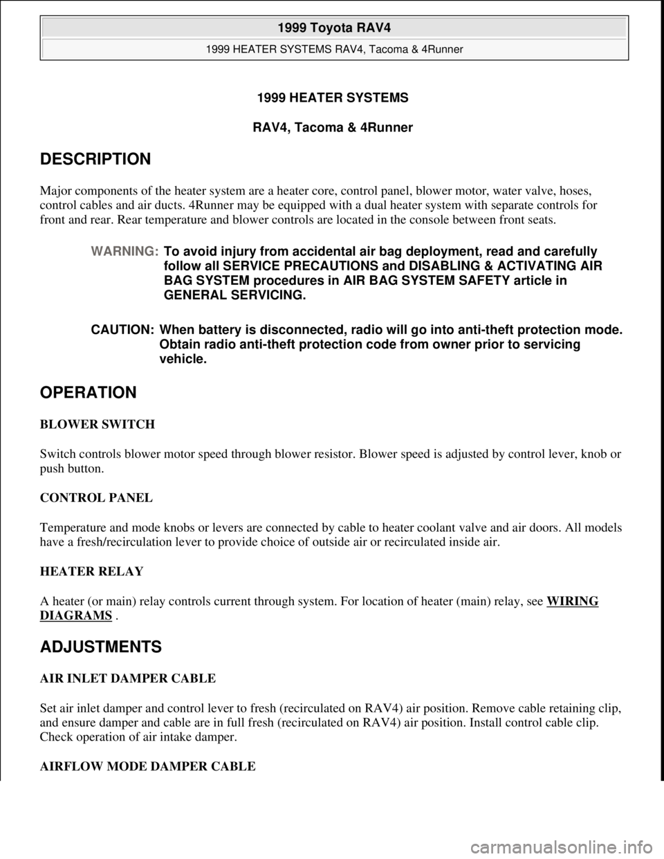
DESCRIPTION
Major components of the heater system are a heater core, control panel, blower motor, water valve, hoses,
control cables and air ducts. 4Runner may be equipped with a dual heater system with separate controls for
front and rear. Rear temperature and blower controls are located in the console between front seats.
OPERATION
BLOWER SWITCH
Switch controls blower motor speed through blower resistor. Blower speed is adjusted by control lever, knob or
push button.
CONTROL PANEL
Temperature and mode knobs or levers are connected by cable to heater coolant valve and air doors. All models
have a fresh/recirculation lever to provide choice of outside air or recirculated inside air.
HEATER RELAY
A heater (or main) relay controls current through system. For location of heater (main) relay, see WIRING
DIAGRAMS .
ADJUSTMENTS
AIR INLET DAMPER CABLE
Set air inlet damper and control lever to fresh (recirculated on RAV4) air position. Remove cable retaining clip,
and ensure damper and cable are in full fresh (recirculated on RAV4) air position. Install control cable clip.
Check operation of air intake damper.
AIRFLOW MODE DAMPER CABLE WARNING:To avoid injury from accidental air bag deployment, read and carefully
follow all SERVICE PRECAUTIONS and DISABLING & ACTIVATING AIR
BAG SYSTEM procedures in AIR BAG SYSTEM SAFETY article in
GENERAL SERVICING.
CAUTION: When battery is disconnected, radio will go into anti-theft protection mode.
Obtain radio anti-theft protection code from owner prior to servicing
vehicle.
1999 Toyota RAV4
1999 HEATER SYSTEMS RAV4, Tacoma & 4Runner
1999 Toyota RAV4
1999 HEATER SYSTEMS RAV4, Tacoma & 4Runner
Microsoft
Sunday, November 22, 2009 10:30:50 AMPage 1 © 2005 Mitchell Repair Information Company, LLC.
Microsoft
Sunday, November 22, 2009 10:30:55 AMPage 1 © 2005 Mitchell Repair Information Company, LLC.
Page 910 of 1632
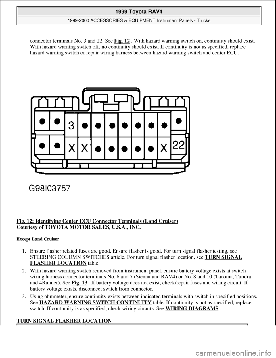
connector terminals No. 3 and 22. See Fig. 12. With hazard warning switch on, continuity should exist.
With hazard warning switch off, no continuity should exist. If continuity is not as specified, replace
hazard warning switch or repair wiring harness between hazard warning switch and center ECU.
Fig. 12: Identifying Center ECU Connector Terminals (Land Cruiser)
Courtesy of TOYOTA MOTOR SALES, U.S.A., INC.
Except Land Cruiser
1. Ensure flasher related fuses are good. Ensure flasher is good. For turn signal flasher testing, see
STEERING COLUMN SWITCHES article. For turn signal flasher location, see TURN SIGNAL
FLASHER LOCATION table.
2. With hazard warning switch removed from instrument panel, ensure battery voltage exists at switch
wiring harness connector terminals No. 6 and 7 (Sienna and RAV4) or No. 8 and 10 (Tacoma, Tundra
and 4Runner). See Fig. 13
. If battery voltage does not exist, check/repair fuses and wiring circuit. If
battery voltage exists, disconnect switch from connector.
3. Using ohmmeter, ensure continuity exists between indicated terminals with switch in specified positions.
See HAZARD WARNING SWITCH CONTINUITY
table. If continuity is not as specified, replace
switch. If continuity is as specified, check wiring circuits. See WIRING DIAGRAMS
.
TURN SIGNAL FLASHER LOCATION
1999 Toyota RAV4
1999-2000 ACCESSORIES & EQUIPMENT Instrument Panels - Trucks
Microsoft
Sunday, November 22, 2009 10:54:10 AMPage 20 © 2005 Mitchell Repair Information Company, LLC.
Page 911 of 1632
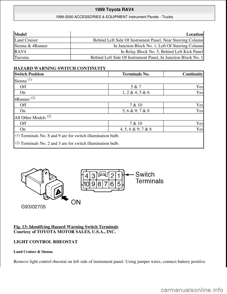
HAZARD WARNING SWITCH CONTINUITY
Fig. 13: Identifying Hazard Warning Switch Terminals
Courtesy of TOYOTA MOTOR SALES, U.S.A., INC.
LIGHT CONTROL RHEOSTAT
Land Cruiser & Sienna
Remove light control rheostat on left side of instrument panel. Using jumper wires, connect battery positive
ModelLocation
Land CruiserBehind Left Side Of Instrument Panel, Near Steering Column
Sienna & 4RunnerIn Junction Block No. 1, Left Of Steering Column
RAV4In Relay Block No. 5, Behind Left Kick Panel
TacomaBehind Left Side Of Instrument Panel, In Junction Block No. 1
Switch PositionTerminals No.Continuity
Sienna (1)
Off5 & 7Yes
On1, 2 & 4; 5 & 6Yes
4Runner (2)
Off7 & 10Yes
On5, 6 & 9; 7 & 8Yes
All Other Models (2)
Off7 & 10Yes
On4, 5, 6 & 9; 7 & 8Yes
(1)Terminals No. 8 and 9 are for switch illumination bulb.
(2)Terminals No. 2 and 3 are for switch illumination bulb.
1999 Toyota RAV4
1999-2000 ACCESSORIES & EQUIPMENT Instrument Panels - Trucks
Microsoft
Sunday, November 22, 2009 10:54:10 AMPage 21 © 2005 Mitchell Repair Information Company, LLC.
Page 914 of 1632
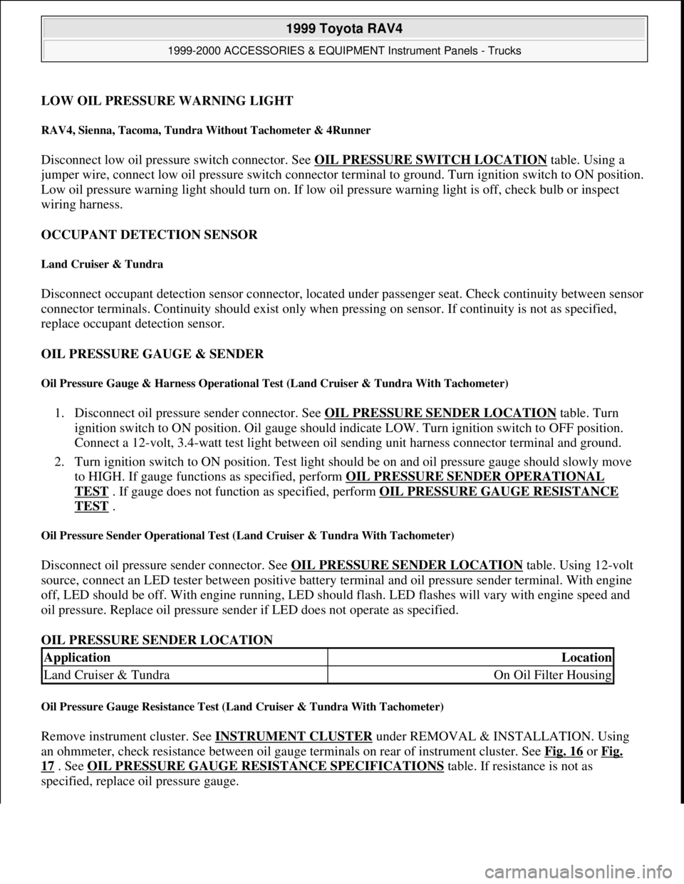
LOW OIL PRESSURE WARNING LIGHT
RAV4, Sienna, Tacoma, Tundra Without Tachometer & 4Runner
Disconnect low oil pressure switch connector. See OIL PRESSURE SWITCH LOCATION table. Using a
jumper wire, connect low oil pressure switch connector terminal to ground. Turn ignition switch to ON position.
Low oil pressure warning light should turn on. If low oil pressure warning light is off, check bulb or inspect
wiring harness.
OCCUPANT DETECTION SENSOR
Land Cruiser & Tundra
Disconnect occupant detection sensor connector, located under passenger seat. Check continuity between sensor
connector terminals. Continuity should exist only when pressing on sensor. If continuity is not as specified,
replace occupant detection sensor.
OIL PRESSURE GAUGE & SENDER
Oil Pressure Gauge & Harness Operational Test (Land Cruiser & Tundra With Tachometer)
1. Disconnect oil pressure sender connector. See OIL PRESSURE SENDER LOCATION table. Turn
ignition switch to ON position. Oil gauge should indicate LOW. Turn ignition switch to OFF position.
Connect a 12-volt, 3.4-watt test light between oil sending unit harness connector terminal and ground.
2. Turn ignition switch to ON position. Test light should be on and oil pressure gauge should slowly move
to HIGH. If gauge functions as specified, perform OIL PRESSURE SENDER OPERATIONAL
TEST . If gauge does not function as specified, perform OIL PRESSURE GAUGE RESISTANCE
TEST .
Oil Pressure Sender Operational Test (Land Cruiser & Tundra With Tachometer)
Disconnect oil pressure sender connector. See OIL PRESSURE SENDER LOCATION table. Using 12-volt
source, connect an LED tester between positive battery terminal and oil pressure sender terminal. With engine
off, LED should be off. With engine running, LED should flash. LED flashes will vary with engine speed and
oil pressure. Replace oil pressure sender if LED does not operate as specified.
OIL PRESSURE SENDER LOCATION
Oil Pressure Gauge Resistance Test (Land Cruiser & Tundra With Tachometer)
Remove instrument cluster. See INSTRUMENT CLUSTER under REMOVAL & INSTALLATION. Using
an ohmmeter, check resistance between oil gauge terminals on rear of instrument cluster. See Fig. 16
or Fig.
17 . See OIL PRESSURE GAUGE RESISTANCE SPECIFICATIONS table. If resistance is not as
specified, replace oil pressure
gauge.
ApplicationLocation
Land Cruiser & TundraOn Oil Filter Housing
1999 Toyota RAV4
1999-2000 ACCESSORIES & EQUIPMENT Instrument Panels - Trucks
Microsoft
Sunday, November 22, 2009 10:54:10 AMPage 24 © 2005 Mitchell Repair Information Company, LLC.
Page 1163 of 1632
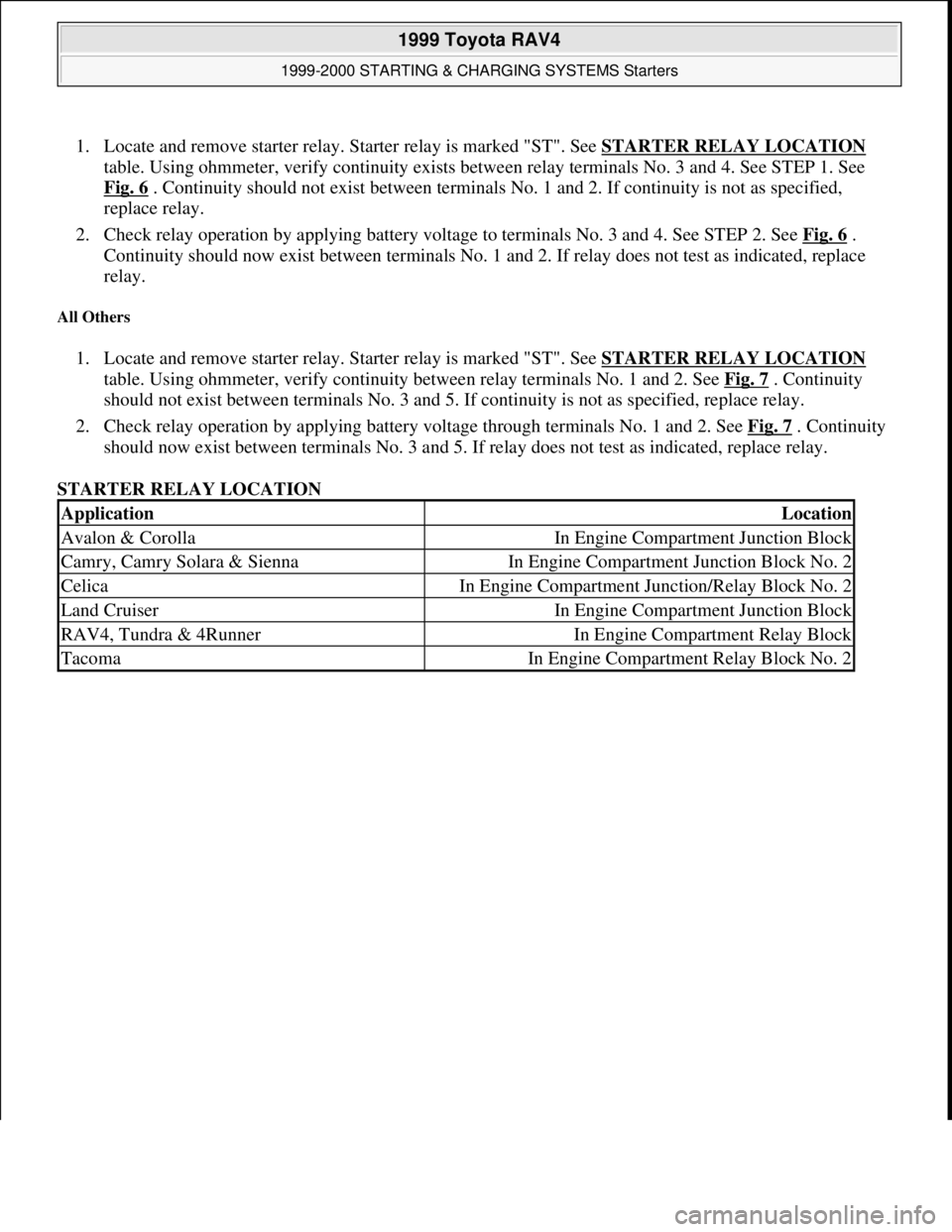
1. Locate and remove starter relay. Starter relay is marked "ST". See STARTER RELAY LOCATION
table. Using ohmmeter, verify continuity exists between relay terminals No. 3 and 4. See STEP 1. See
Fig. 6
. Continuity should not exist between terminals No. 1 and 2. If continuity is not as specified,
replace relay.
2. Check relay operation by applying battery voltage to terminals No. 3 and 4. See STEP 2. See Fig. 6
.
Continuity should now exist between terminals No. 1 and 2. If relay does not test as indicated, replace
relay.
All Others
1. Locate and remove starter relay. Starter relay is marked "ST". See STARTER RELAY LOCATION
table. Using ohmmeter, verify continuity between relay terminals No. 1 and 2. See Fig. 7
. Continuity
should not exist between terminals No. 3 and 5. If continuity is not as specified, replace relay.
2. Check relay operation by applying battery voltage through terminals No. 1 and 2. See Fig. 7
. Continuity
should now exist between terminals No. 3 and 5. If relay does not test as indicated, replace relay.
STARTER RELAY LOCATION
ApplicationLocation
Avalon & CorollaIn Engine Compartment Junction Block
Camry, Camry Solara & SiennaIn Engine Compartment Junction Block No. 2
CelicaIn Engine Compartment Junction/Relay Block No. 2
Land CruiserIn Engine Compartment Junction Block
RAV4, Tundra & 4RunnerIn Engine Compartment Relay Block
TacomaIn Engine Compartment Relay Block No. 2
1999 Toyota RAV4
1999-2000 STARTING & CHARGING SYSTEMS Starters
Microsoft
Sunday, November 22, 2009 10:19:18 AMPage 8 © 2005 Mitchell Repair Information Company, LLC.