Motor oil TOYOTA RAV4 1996 Service Repair Manual
[x] Cancel search | Manufacturer: TOYOTA, Model Year: 1996, Model line: RAV4, Model: TOYOTA RAV4 1996Pages: 1632, PDF Size: 41.64 MB
Page 15 of 1632
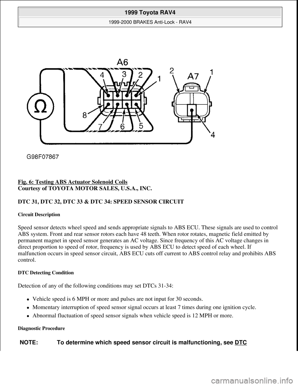
Fig. 6: Testing ABS Actuator Solenoid Coils
Courtesy of TOYOTA MOTOR SALES, U.S.A., INC.
DTC 31, DTC 32, DTC 33 & DTC 34: SPEED SENSOR CIRCUIT
Circuit Description
Speed sensor detects wheel speed and sends appropriate signals to ABS ECU. These signals are used to control
ABS system. Front and rear sensor rotors each have 48 teeth. When rotor rotates, magnetic field emitted by
permanent magnet in speed sensor generates an AC voltage. Since frequency of this AC voltage changes in
direct proportion to speed of rotor, frequency is used by ABS ECU to detect speed of each wheel. If
malfunction occurs in speed sensor circuit, ABS ECU cuts off current to ABS control relay and prohibits ABS
control.
DTC Detecting Condition
Detection of any of the following conditions may set DTCs 31-34:
Vehicle speed is 6 MPH or more and pulses are not input for 30 seconds.
Momentary interruption of speed sensor signal occurs at least 7 times during one ignition cycle.
Abnormal fluctuation of speed sensor signals when vehicle speed is 12 MPH or more.
Diagnostic Procedure
NOTE: To determine which speed sensor circuit is malfunctioning, see DTC
1999 Toyota RAV4
1999-2000 BRAKES Anti-Lock - RAV4
Microsoft
Sunday, November 22, 2009 10:06:17 AMPage 15 © 2005 Mitchell Repair Information Company, LLC.
Page 115 of 1632
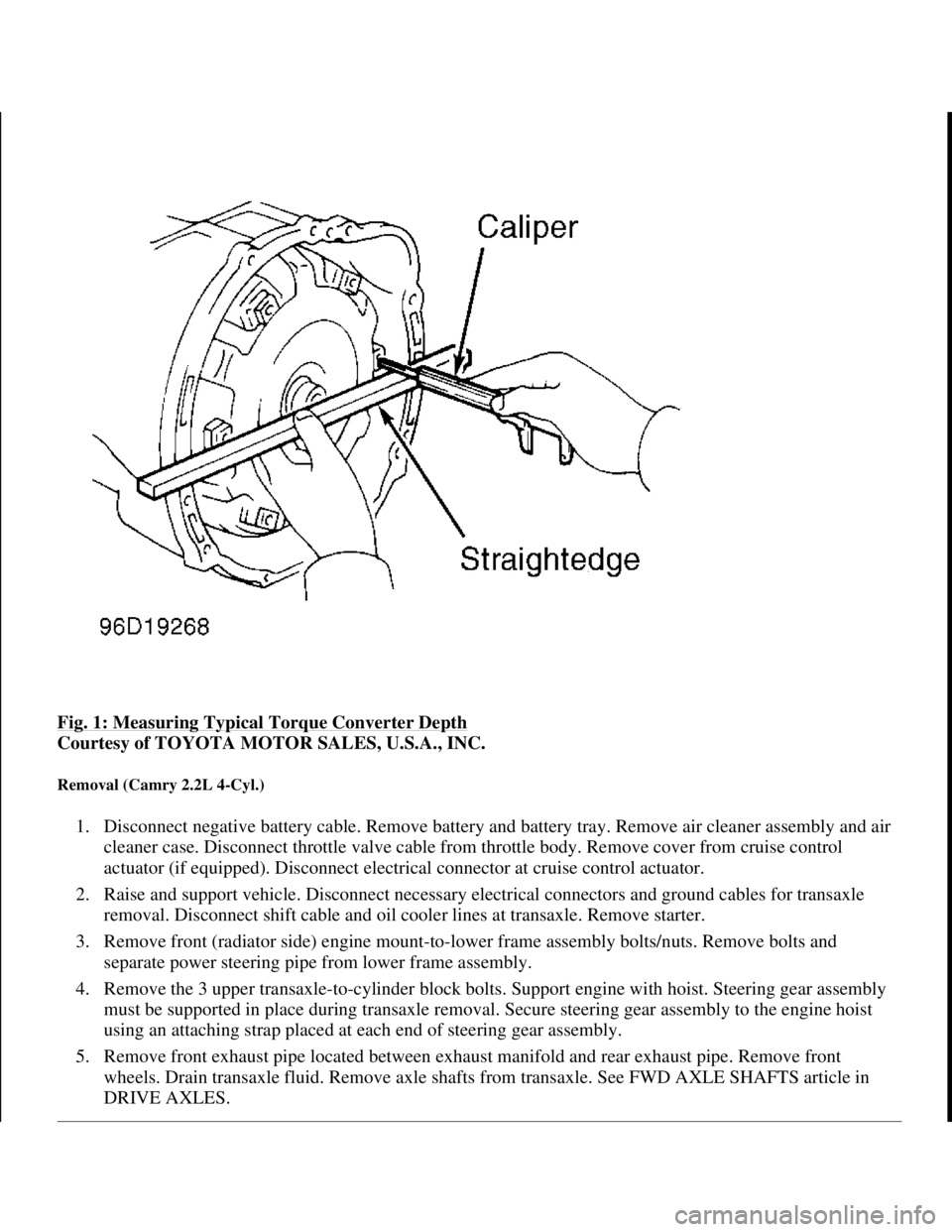
Fig. 1: Measuring Typical Torque Converter Depth
Courtesy of TOYOTA MOTOR SALES, U.S.A., INC.
Removal (Camry 2.2L 4-Cyl.)
1. Disconnect negative battery cable. Remove battery and battery tray. Remove air cleaner assembly and air
cleaner case. Disconnect throttle valve cable from throttle body. Remove cover from cruise control
actuator (if equipped). Disconnect electrical connector at cruise control actuator.
2. Raise and support vehicle. Disconnect necessary electrical connectors and ground cables for transaxle
removal. Disconnect shift cable and oil cooler lines at transaxle. Remove starter.
3. Remove front (radiator side) engine mount-to-lower frame assembly bolts/nuts. Remove bolts and
separate power steering pipe from lower frame assembly.
4. Remove the 3 upper transaxle-to-cylinder block bolts. Support engine with hoist. Steering gear assembly
must be supported in place during transaxle removal. Secure steering gear assembly to the engine hoist
using an attaching strap placed at each end of steering gear assembly.
5. Remove front exhaust pipe located between exhaust manifold and rear exhaust pipe. Remove front
wheels. Drain transaxle fluid. Remove axle shafts from transaxle. See FWD AXLE SHAFTS article in
DRIVE AXLES.
1998 Toyota Avalon XLS
TRANSMISSION SERVICING - A/T 1997-98 TRANSMISSION SERVICING Toyota - Transmission Removal &
Installation
Helpmelearn
November-03-08 10:30:28 AMPage 3 © 2005 Mitchell Repair Information Company, LLC.
Page 130 of 1632
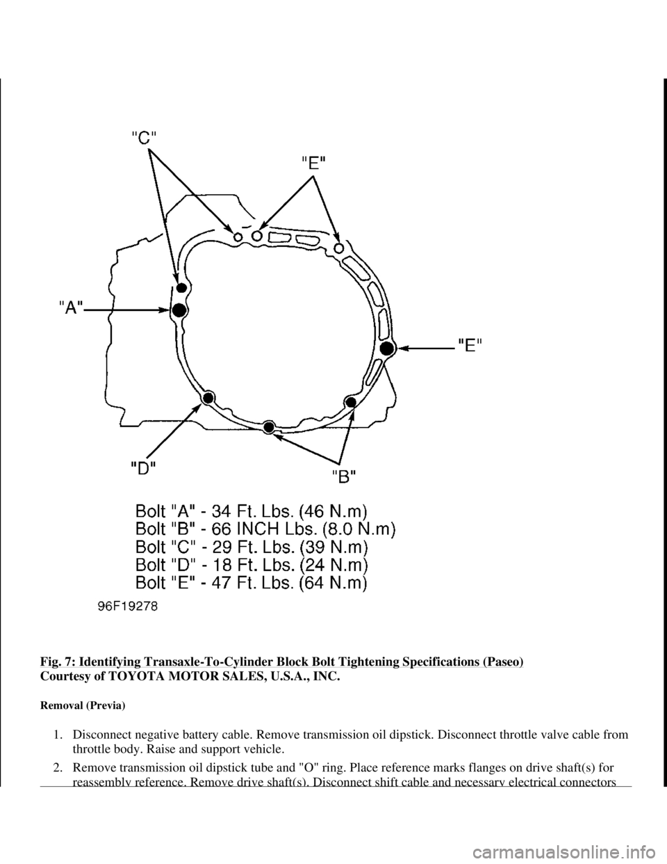
Fig. 7: Identifying Transaxle-To-Cylinder Block Bolt Tightening Specifications (Paseo)
Courtesy of TOYOTA MOTOR SALES, U.S.A., INC.
Removal (Previa)
1. Disconnect negative battery cable. Remove transmission oil dipstick. Disconnect throttle valve cable from
throttle body. Raise and support vehicle.
2. Remove transmission oil dipstick tube and "O" ring. Place reference marks flanges on drive shaft(s) for
reassembl
y reference. Remove drive shaft(s). Disconnect shift cable and necessary electrical connectors
1998 Toyota Avalon XLS
TRANSMISSION SERVICING - A/T 1997-98 TRANSMISSION SERVICING Toyota - Transmission Removal &
Installation
Helpmelearn
November-03-08 10:30:28 AMPage 18 © 2005 Mitchell Repair Information Company, LLC.
Page 158 of 1632
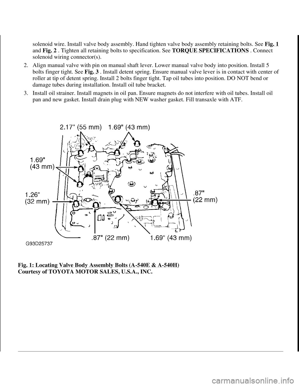
solenoid wire. Install valve body assembly. Hand tighten valve body assembly retaining bolts. See Fig. 1
and Fig. 2 . Tighten all retaining bolts to specification. See TORQUE SPECIFICATIONS . Connect
solenoid wiring connector(s).
2. Align manual valve with pin on manual shaft lever. Lower manual valve body into position. Install 5
bolts finger tight. See Fig. 3
. Install detent spring. Ensure manual valve lever is in contact with center of
roller at tip of detent spring. Install 2 bolts finger tight. Tap oil tubes into position. DO NOT bend or
damage tubes during installation. Install oil tube bracket.
3. Install oil strainer. Install magnets in oil pan. Ensure magnets do not interfere with oil tubes. Install oil
pan and new gasket. Install drain plug with NEW washer gasket. Fill transaxle with ATF.
Fig. 1: Locating Valve Body Assembly Bolts (A
-540E & A-540H)
Courtesy of TOYOTA MOTOR SALES, U.S.A., INC.
1998 Toyota Avalon XLS
1997-99 AUTOMATIC TRANSMISSIONS Toyota A-540E, A-540H & A-541E Overhaul
Helpmelearn
November-03-08 10:28:16 AMPage 4 © 2005 Mitchell Repair Information Company, LLC.
Page 174 of 1632
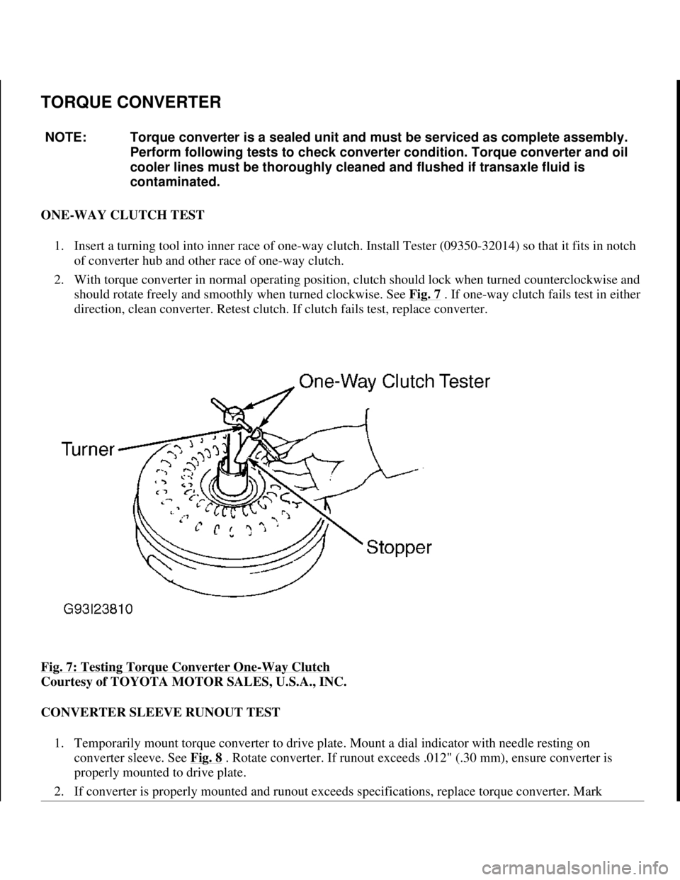
TORQUE CONVERTER
ONE-WAY CLUTCH TEST
1. Insert a turning tool into inner race of one-way clutch. Install Tester (09350-32014) so that it fits in notch
of converter hub and other race of one-way clutch.
2. With torque converter in normal operating position, clutch should lock when turned counterclockwise and
should rotate freely and smoothly when turned clockwise. See Fig. 7
. If one-way clutch fails test in either
direction, clean converter. Retest clutch. If clutch fails test, replace converter.
Fig. 7: Testing Torque Converter One
-Way Clutch
Courtesy of TOYOTA MOTOR SALES, U.S.A., INC.
CONVERTER SLEEVE RUNOUT TEST
1. Temporarily mount torque converter to drive plate. Mount a dial indicator with needle resting on
converter sleeve. See Fig. 8
. Rotate converter. If runout exceeds .012" (.30 mm), ensure converter is
properly mounted to drive plate.
2. If converter is properl
y mounted and runout exceeds specifications, replace torque converter. Mark NOTE: Torque converter is a sealed unit and must be serviced as complete assembly.
Perform following tests to check converter condition. Torque converter and oil
cooler lines must be thoroughly cleaned and flushed if transaxle fluid is
contaminated.
1998 Toyota Avalon XLS
1997-99 AUTOMATIC TRANSMISSIONS Toyota A-540E, A-540H & A-541E Overhaul
Helpmelearn
November-03-08 10:28:17 AMPage 20 © 2005 Mitchell Repair Information Company, LLC.
Page 176 of 1632
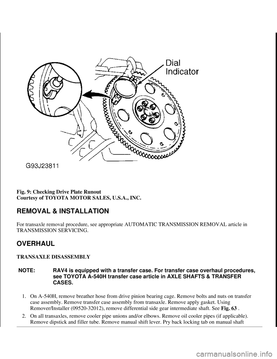
Fig. 9: Checking Drive Plate Runout
Courtesy of TOYOTA MOTOR SALES, U.S.A., INC.
REMOVAL & INSTALLATION
For transaxle removal procedure, see appropriate AUTOMATIC TRANSMISSION REMOVAL article in
TRANSMISSION SERVICING.
OVERHAUL
TRANSAXLE DISASSEMBLY
1. On A-540H, remove breather hose from drive pinion bearing cage. Remove bolts and nuts on transfer
case assembly. Remove transfer case assembly from transaxle. Remove apply gasket. Using
Remover/Installer (09520-32012), remove differential side gear intermediate shaft. See Fig. 63
.
2. On all transaxles, remove cooler pipe unions and/or elbows. Remove oil cooler pipes (if applicable).
Remove dipstick and filler tube. Remove manual shift lever. Pry back locking tab on manual shaft
NOTE: RAV4 is equipped with a transfer case. For transfer case overhaul procedures,
see TOYOTA A-540H transfer case article in AXLE SHAFTS & TRANSFER
CASES.
1998 Toyota Avalon XLS
1997-99 AUTOMATIC TRANSMISSIONS Toyota A-540E, A-540H & A-541E Overhaul
Helpmelearn
November-03-08 10:28:17 AMPage 22 © 2005 Mitchell Repair Information Company, LLC.
Page 183 of 1632
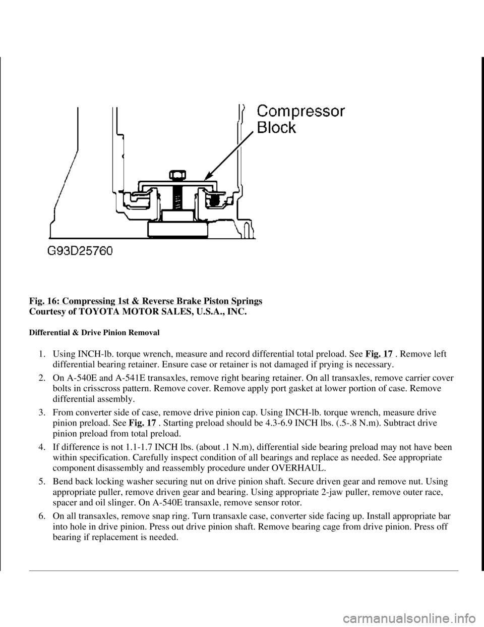
Fig. 16: Compressing 1st & Reverse Brake Piston Springs
Courtesy of TOYOTA MOTOR SALES, U.S.A., INC.
Differential & Drive Pinion Removal
1. Using INCH-lb. torque wrench, measure and record differential total preload. See Fig. 17 . Remove left
differential bearing retainer. Ensure case or retainer is not damaged if prying is necessary.
2. On A-540E and A-541E transaxles, remove right bearing retainer. On all transaxles, remove carrier cover
bolts in crisscross pattern. Remove cover. Remove apply port gasket at lower portion of case. Remove
differential assembly.
3. From converter side of case, remove drive pinion cap. Using INCH-lb. torque wrench, measure drive
pinion preload. See Fig. 17
. Starting preload should be 4.3-6.9 INCH lbs. (.5-.8 N.m). Subtract drive
pinion preload from total preload.
4. If difference is not 1.1-1.7 INCH lbs. (about .1 N.m), differential side bearing preload may not have been
within specification. Carefully inspect condition of all bearings and replace as needed. See appropriate
component disassembly and reassembly procedure under OVERHAUL.
5. Bend back locking washer securing nut on drive pinion shaft. Secure driven gear and remove nut. Using
appropriate puller, remove driven gear and bearing. Using appropriate 2-jaw puller, remove outer race,
spacer and oil slinger. On A-540E transaxle, remove sensor rotor.
6. On all transaxles, remove snap ring. Turn transaxle case, converter side facing up. Install appropriate bar
into hole in drive pinion. Press out drive pinion shaft. Remove bearing cage from drive pinion. Press off
bearing if replacement is needed.
1998 Toyota Avalon XLS
1997-99 AUTOMATIC TRANSMISSIONS Toyota A-540E, A-540H & A-541E Overhaul
Helpmelearn
November-03-08 10:28:17 AMPage 29 © 2005 Mitchell Repair Information Company, LLC.
Page 184 of 1632
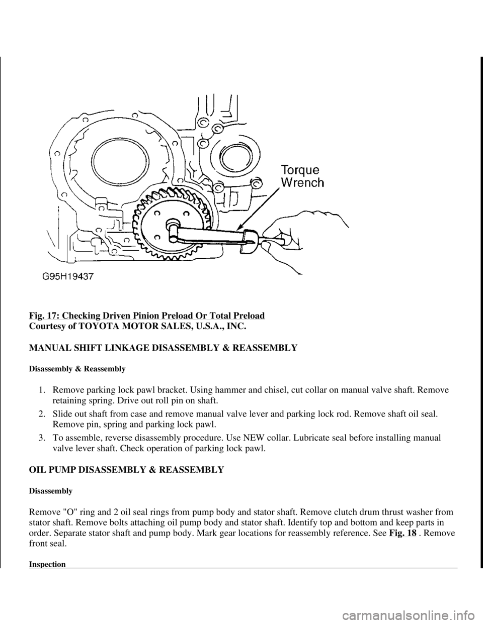
Fig. 17: Checking Driven Pinion Preload Or Total Preload
Courtesy of TOYOTA MOTOR SALES, U.S.A., INC.
MANUAL SHIFT LINKAGE DISASSEMBLY & REASSEMBLY
Disassembly & Reassembly
1. Remove parking lock pawl bracket. Using hammer and chisel, cut collar on manual valve shaft. Remove
retaining spring. Drive out roll pin on shaft.
2. Slide out shaft from case and remove manual valve lever and parking lock rod. Remove shaft oil seal.
Remove pin, spring and parking lock pawl.
3. To assemble, reverse disassembly procedure. Use NEW collar. Lubricate seal before installing manual
valve lever shaft. Check operation of parking lock pawl.
OIL PUMP DISASSEMBLY & REASSEMBLY
Disassembly
Remove "O" ring and 2 oil seal rings from pump body and stator shaft. Remove clutch drum thrust washer from
stator shaft. Remove bolts attaching oil pump body and stator shaft. Identify top and bottom and keep parts in
order. Separate stator shaft and pump body. Mark gear locations for reassembly reference. See Fig. 18
. Remove
front seal.
Inspection
1998 Toyota Avalon XLS
1997-99 AUTOMATIC TRANSMISSIONS Toyota A-540E, A-540H & A-541E Overhaul
Helpmelearn
November-03-08 10:28:17 AMPage 30 © 2005 Mitchell Repair Information Company, LLC.
Page 186 of 1632
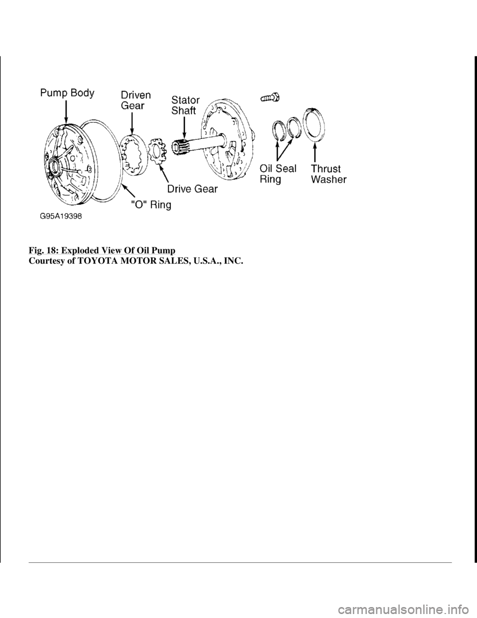
Fig. 18: Exploded View Of Oil Pump
Courtesy of TOYOTA MOTOR SALES, U.S.A., INC.
1998 Toyota Avalon XLS
1997-99 AUTOMATIC TRANSMISSIONS Toyota A-540E, A-540H & A-541E Overhaul
Helpmelearn
November-03-08 10:28:17 AMPage 32 © 2005 Mitchell Repair Information Company, LLC.
Page 187 of 1632
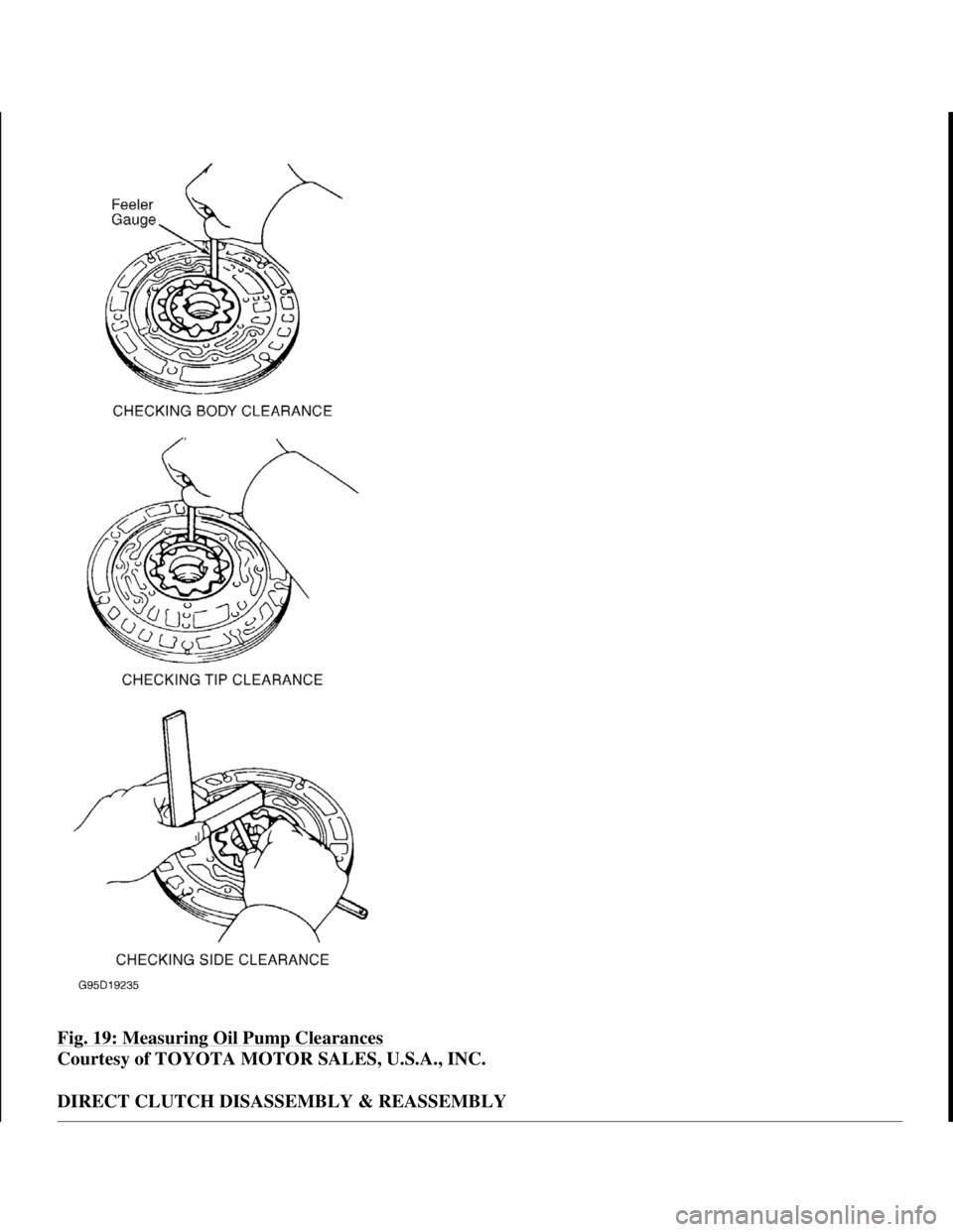
Fig. 19: Measuring Oil Pump Clearances
Courtesy of TOYOTA MOTOR SALES, U.S.A., INC.
DIRECT CLUTCH DISASSEMBLY & REASSEMBLY
1998 Toyota Avalon XLS
1997-99 AUTOMATIC TRANSMISSIONS Toyota A-540E, A-540H & A-541E Overhaul
Helpmelearn
November-03-08 10:28:17 AMPage 33 © 2005 Mitchell Repair Information Company, LLC.