Vacuum TOYOTA RAV4 1996 Service Repair Manual
[x] Cancel search | Manufacturer: TOYOTA, Model Year: 1996, Model line: RAV4, Model: TOYOTA RAV4 1996Pages: 1632, PDF Size: 41.64 MB
Page 31 of 1632
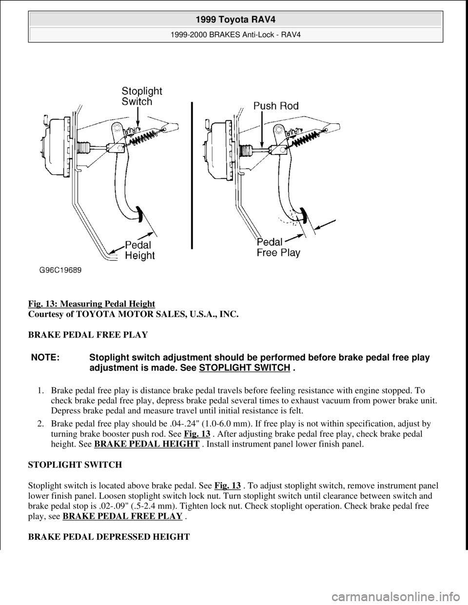
Fig. 13: Measuring Pedal Height
Courtesy of TOYOTA MOTOR SALES, U.S.A., INC.
BRAKE PEDAL FREE PLAY
1. Brake pedal free play is distance brake pedal travels before feeling resistance with engine stopped. To
check brake pedal free play, depress brake pedal several times to exhaust vacuum from power brake unit.
Depress brake pedal and measure travel until initial resistance is felt.
2. Brake pedal free play should be .04-.24" (1.0-6.0 mm). If free play is not within specification, adjust by
turning brake booster push rod. See Fig. 13
. After adjusting brake pedal free play, check brake pedal
height. See BRAKE PEDAL HEIGHT
. Install instrument panel lower finish panel.
STOPLIGHT SWITCH
Stoplight switch is located above brake pedal. See Fig. 13
. To adjust stoplight switch, remove instrument panel
lower finish panel. Loosen stoplight switch lock nut. Turn stoplight switch until clearance between switch and
brake pedal stop is .02-.09" (.5-2.4 mm). Tighten lock nut. Check stoplight operation. Check brake pedal free
play, see BRAKE PEDAL FREE PLAY .
BRAKE PEDAL DEPRESSED HEIGHT
NOTE: Stoplight switch adjustment should be performed before brake pedal free play
adjustment is made. See STOPLIGHT SWITCH
.
1999 Toyota RAV4
1999-2000 BRAKES Anti-Lock - RAV4
Microsoft
Sunday, November 22, 2009 10:06:17 AMPage 31 © 2005 Mitchell Repair Information Company, LLC.
Page 340 of 1632
1999-2000 BRAKES
Disc & Drum - Trucks & Vans
DESCRIPTION & OPERATION
Hydraulic brake system uses a tandem master cylinder with a vacuum power assist servo. All models (except
Land Cruiser) are equipped with front disc brakes and rear drum brakes standard. Rear disc brakes are standard
on Land Cruiser models.
A Load-Sensing Proportioning Valve (LSVP) is used to regulate brake pressure between front and rear brakes.
Rear brakes on all models are self-adjusting.
Parking brake lever mechanically activates rear brakes. On models with rear drum brakes, a cable applies rear
shoes. On models with rear disc brakes, parking brake is a drum brake internal to rear disc assembly.
BLEEDING BRAKE SYSTEM
BLEEDING PROCEDURES
1. If master cylinder is rebuilt or reservoir is empty, bleed master cylinder first. Bleed wheels in sequence.
Start on wheel with longest hydraulic line, and work toward wheel with shortest hydraulic line.
2. Raise and support vehicle. Ensure brake fluid reservoir is at least half full during bleeding procedure.
Connect one end of transparent vinyl tube to bleeder screw. Submerge other end of tube in a container
half filled with clean brake fluid.
3. Have an assistant depress brake pedal several times and hold in depressed position. Loosen bleeder screw,
and drain fluid into container. Tighten bleeder screw. WARNING:For warnings and procedures regarding vehicles equipped with Anti-Lock
Brake Systems (ABS), see appropriate ANTI-LOCK article.
NOTE: For disc brake coverage on Lexus LX470, see Land Cruiser information in this
article. The 1999 Land Cruiser and Lexus LX470 information is the same. The
2000 Land Cruiser information for models equipped with traction control ABS is
the same on 2000 LX470. Models with traction control ABS do not use a Load-
Sensing Proportioning Valve (lspv) and By-Pass Valve (BPV).
CAUTION: DO NOT allow reservoir to run dry during brake bleeding procedure. Use
only clean brake fluid. Ensure no dirt or other foreign matter contaminates
brake fluid. DO NOT mix different types of brake fluid, as they may not be
compatible. DO NOT spill brake fluid on vehicle, as it may damage paint. If
brake fluid contacts paint, immediately wash with water.
NOTE: Ensure brake pedal remains depressed until bleeder screw is tightened.
1999 Toyota RAV4
1999-2000 BRAKES Disc & Drum - Trucks & Vans
1999 Toyota RAV4
1999-2000 BRAKES Disc & Drum - Trucks & Vans
Microsoft
Sunday, November 22, 2009 10:07:28 AMPage 1 © 2005 Mitchell Repair Information Company, LLC.
Microsoft
Sunday, November 22, 2009 10:07:32 AMPage 1 © 2005 Mitchell Repair Information Company, LLC.
Page 342 of 1632
BRAKE PEDAL FREE PLAY
1. Brake pedal free play is distance brake pedal travels before feeling resistance with engine stopped. To
check pedal free play, depress brake pedal several times to exhaust vacuum from booster.
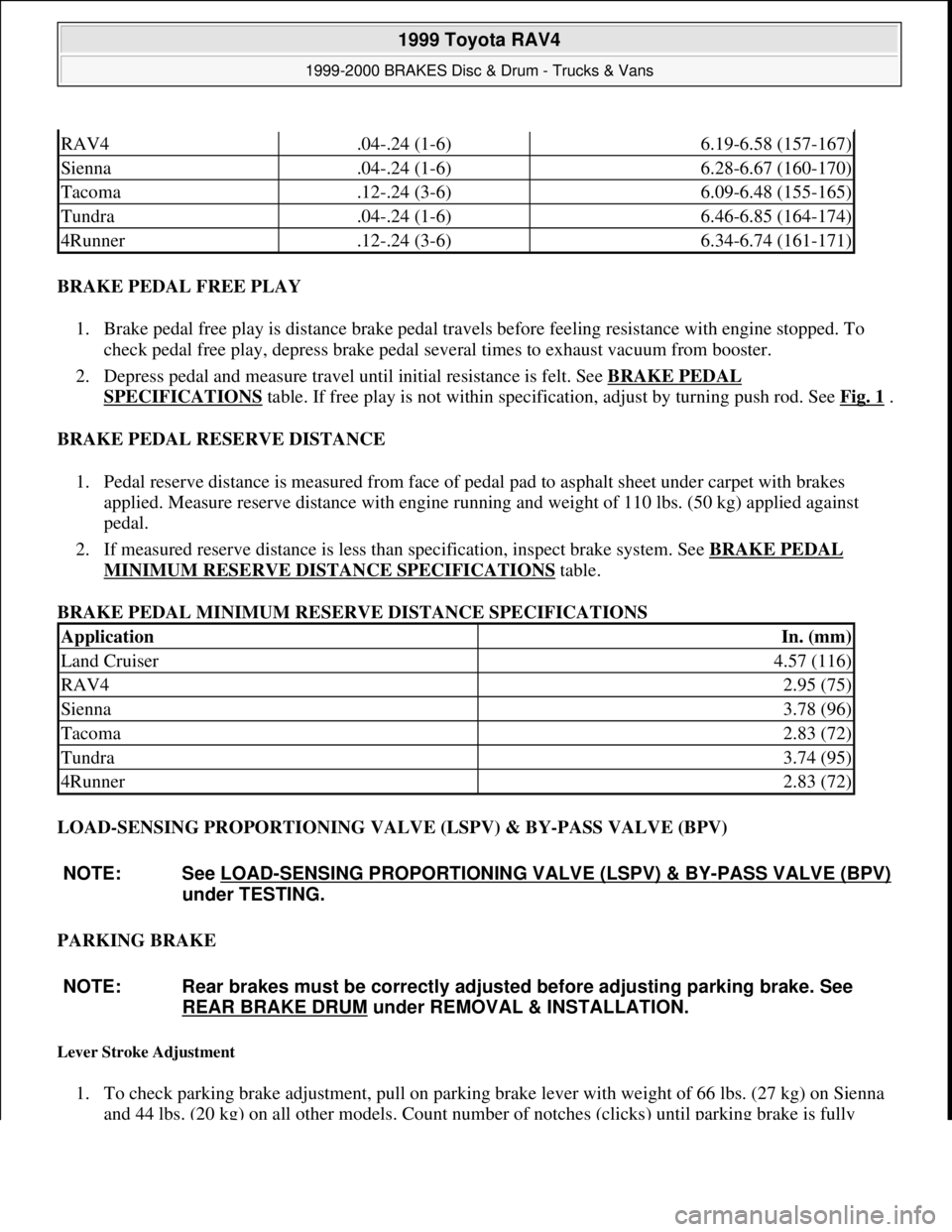
2. Depress pedal and measure travel until initial resistance is felt. See BRAKE PEDAL
SPECIFICATIONS table. If free play is not within specification, adjust by turning push rod. See Fig. 1.
BRAKE PEDAL RESERVE DISTANCE
1. Pedal reserve distance is measured from face of pedal pad to asphalt sheet under carpet with brakes
applied. Measure reserve distance with engine running and weight of 110 lbs. (50 kg) applied against
pedal.
2. If measured reserve distance is less than specification, inspect brake system. See BRAKE PEDAL
MINIMUM RESERVE DISTANCE SPECIFICATIONS table.
BRAKE PEDAL MINIMUM RESERVE DISTANCE SPECIFICATIONS
LOAD-SENSING PROPORTIONING VALVE (LSPV) & BY-PASS VALVE (BPV)
PARKING BRAKE
Lever Stroke Adjustment
1. To check parking brake adjustment, pull on parking brake lever with weight of 66 lbs. (27 kg) on Sienna
and 44 lbs. (20 k
g) on all other models. Count number of notches (clicks) until parking brake is fully
RAV4.04-.24 (1-6)6.19-6.58 (157-167)
Sienna.04-.24 (1-6)6.28-6.67 (160-170)
Tacoma.12-.24 (3-6)6.09-6.48 (155-165)
Tundra.04-.24 (1-6)6.46-6.85 (164-174)
4Runner.12-.24 (3-6)6.34-6.74 (161-171)
ApplicationIn. (mm)
Land Cruiser4.57 (116)
RAV42.95 (75)
Sienna3.78 (96)
Tacoma2.83 (72)
Tundra3.74 (95)
4Runner2.83 (72)
NOTE: See LOAD
-SENSING PROPORTIONING VALVE (LSPV) & BY-PASS VALVE (BPV)
under TESTING.
NOTE: Rear brakes must be correctly adjusted before adjusting parking brake. See
REAR BRAKE DRUM
under REMOVAL & INSTALLATION.
1999 Toyota RAV4
1999-2000 BRAKES Disc & Drum - Trucks & Vans
Microsoft
Sunday, November 22, 2009 10:07:28 AMPage 3 © 2005 Mitchell Repair Information Company, LLC.
Page 364 of 1632
1. Disconnect fluid level warning switch connector. Remove fluid from master cylinder with syringe.
Remove 2 bolts, and move relay box aside. Remove air cleaner housing and hose.
2. Disconnect brake lines and 3-way line connector from master cylinder. If equipped with M/T, disconnect
clutch reservoir hose. On all models, remove 2 bolts and master cylinder.
3. Prior to installation, adjust length of brake booster push rod if necessary. See POWER BRAKE UNIT
PUSH ROD under ADJUSTMENTS.
4. Install master cylinder in reverse of removal procedure. Use NEW gasket. Fill and bleed system. Check
for leaks and adjust pedal, if needed. Bleed clutch system, if equipped.
Removal & Installation (Sienna)
1. Remove air cleaner assembly. Disconnect fluid level warning switch connector. Remove fluid from
master cylinder with syringe. Remove fluid reservoir tank and bracket (2 bolts).
2. Disconnect brake lines from master cylinder. Remove 2 bolts and master cylinder.
3. Prior to installation, adjust length of brake booster push rod if necessary. See POWER BRAKE UNIT
PUSH ROD under ADJUSTMENTS.
4. Install master cylinder in reverse of removal procedure. Use NEW gasket. Fill and bleed system. Check
for leaks and adjust pedal, if needed. Bleed clutch system, if equipped.
Removal & Installation (Tacoma, Tundra & 4Runner)
1. Unplug fluid level sensor lead. Drain brake fluid from reservoir. Disconnect and plug hydraulic lines.
Remove master cylinder-to-power brake unit nuts. Remove master cylinder.
2. If master cylinder has been overhauled or replaced, check and adjust power brake unit push rod. See
POWER BRAKE UNIT PUSH ROD
under ADJUSTMENTS. To install, reverse removal procedure.
Bleed brake system. See BLEEDING BRAKE SYSTEM
.
POWER BRAKE UNIT
Removal & Installation (RAV4, Tacoma, Tundra & 4Runner)
1. Remove master cylinder. See MASTER CYLINDER . On RAV4, remove charcoal canister. On all
models, disconnect vacuum hose. On Tundra, remove scuff plate LH, cowl side trim LH, lower finish
panel and No. 2 heater to register duct. On all models, remove brake pedal return spring, clip and clevis
pin. On Tundra, remove 4 nuts, clevis, brake booster and gasket. Remove 2 stopper rings, brake booster
bracket and gasket from brake booster. Remove power brake unit.
2. Install power brake unit. On Tundra, install NEW gasket to power brake unit. Install bracket and stopper
rings. Install clevis to operating rod. On all models, attach clevis pin, clip and return spring. Adjust push
rod length. See POWER BRAKE UNIT PUSH ROD
under ADJUSTMENTS.
3. Install master cylinder with NEW gasket. Connect vacuum hose. Fill master cylinder. Bleed system and
check for leaks. Adjust brake pedal, if necessary.
Removal & Installation (Sienna)
1. Remove 2 cowl top vent louvers and outer front cowl top panel. See Fig. 16 . Remove master cylinder.
1999 Toyota RAV4
1999-2000 BRAKES Disc & Drum - Trucks & Vans
Microsoft
Sunday, November 22, 2009 10:07:28 AMPage 25 © 2005 Mitchell Repair Information Company, LLC.
Page 365 of 1632
See MASTER CYLINDER .
2. Remove ABS actuator assembly. Disconnect vacuum hose from power brake unit. Remove lower
instrument panel finish panels to access brake pedal arm. Remove Cruise Control Engine Control Unit
(ECU). Remove pedal return spring, clip and clevis pin.
3. Remove 4 nuts and clevis, and remove power brake unit.
4. Install power brake unit. Attach clevis pin, clip and return spring. Install Cruise Control Engine Control
Unit (ECU). Adjust push rod length. See POWER BRAKE UNIT PUSH ROD
under ADJUSTMENTS.
5. Install master cylinder with NEW gasket. Connect vacuum hose. Fill master cylinder. Bleed system and
check for leads. Adjust brake pedal, if necessary. Install cowl panel and vent louvers.
1999 Toyota RAV4
1999-2000 BRAKES Disc & Drum - Trucks & Vans
Microsoft
Sunday, November 22, 2009 10:07:28 AMPage 26 © 2005 Mitchell Repair Information Company, LLC.
Page 384 of 1632
1999-2000 DRIVE AXLES
Center Differential Lock
DESCRIPTION & OPERATION
CENTER DIFFERENTIAL LOCK SYSTEM
The center differential lock system enables vehicle to have enough traction to move when one of the 4 wheels,
both front wheels or both rear wheels are off the ground or on a slippery surface.
Center differential lock system consists of control switch, differential lock control solenoids, differential lock
actuator, indicator switch, and integration relay. See Fig. 1
.
With control switch off, the center differential lock indicator light on instrument panel is off, along with
vacuum switching valves No. 1 and 2. Vacuum switching valve No. 1 draws vacuum from vacuum tank to
chamber "A" of the vacuum actuator. Vacuum switching valve No. 2 draws atmospheric air to chamber "B".
Under these conditions, the vacuum actuator diaphragm moves the rod, which moves the locking sleeve shift
fork and shaft, which causes the locking sleeve to disengage from the case. See Fig. 2
. During this time, the
center differential warning buzzer will sound. When the locking sleeve is completely disengaged, the warning
buzzer will turn off (free position).
1999 Toyota RAV4
1999-2000 DRIVE AXLES Center Differential Lock
1999 Toyota RAV4
1999-2000 DRIVE AXLES Center Differential Lock
Microsoft
Sunday, November 22, 2009 10:08:59 AMPage 1 © 2005 Mitchell Repair Information Company, LLC.
Microsoft
Sunday, November 22, 2009 10:09:03 AMPage 1 © 2005 Mitchell Repair Information Company, LLC.
Page 387 of 1632
Change position of vacuum hoses at vacuum switching valves.
2. Turn off center differential lock switch and ensure warning buzzer sounds. Change position of vacuum
hoses at vacuum switching valves once again, and ensure buzzer stops. If buzzer operation is not as
specified, check vacuum hoses.
TESTING
CENTER DIFFERENTIAL LOCK ACTUATOR
Vacuum Tank Chamber
Disconnect vacuum hoses (except No. 1) and plug hose No. 3. See Fig. 3. Apply 20" Hg of vacuum to hose No.
0 and ensure indicator needle remains steady. Actuator may leak 1.7" Hg or less during 15 seconds.
Lock Chamber
Disconnect vacuum hoses No. 1 and 2. Apply 20" Hg of vacuum to hose No. 1 and ensure indicator needle
remains steady. Actuator may leak 1.7" Hg or less during 15 seconds.
Free Chamber
Disconnect all vacuum hoses and plug hose No. 3. Using a "T" fitting, apply 20" Hg of vacuum to hoses No. 0
and 2. Ensure indicator needle remains steady. Actuator may leak 1.7" Hg or less during 15 seconds. NOTE: If actuator operation is not as specified, replace actuator.
1999 Toyota RAV4
1999-2000 DRIVE AXLES Center Differential Lock
Microsoft
Sunday, November 22, 2009 10:08:59 AMPage 4 © 2005 Mitchell Repair Information Company, LLC.
Page 389 of 1632
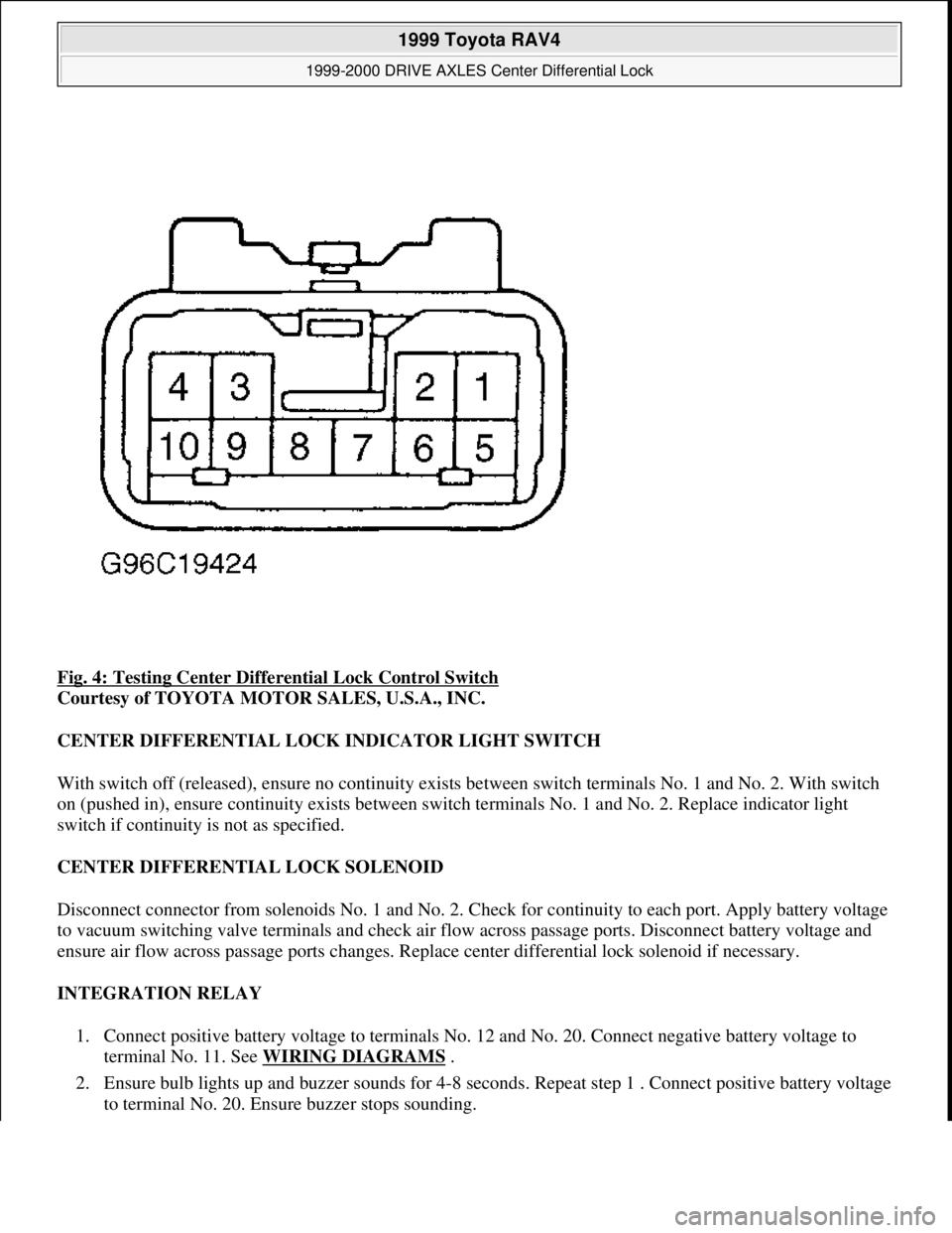
Fig. 4: Testing Center Differential Lock Control Switch
Courtesy of TOYOTA MOTOR SALES, U.S.A., INC.
CENTER DIFFERENTIAL LOCK INDICATOR LIGHT SWITCH
With switch off (released), ensure no continuity exists between switch terminals No. 1 and No. 2. With switch
on (pushed in), ensure continuity exists between switch terminals No. 1 and No. 2. Replace indicator light
switch if continuity is not as specified.
CENTER DIFFERENTIAL LOCK SOLENOID
Disconnect connector from solenoids No. 1 and No. 2. Check for continuity to each port. Apply battery voltage
to vacuum switching valve terminals and check air flow across passage ports. Disconnect battery voltage and
ensure air flow across passage ports changes. Replace center differential lock solenoid if necessary.
INTEGRATION RELAY
1. Connect positive battery voltage to terminals No. 12 and No. 20. Connect negative battery voltage to
terminal No. 11. See WIRING DIAGRAMS
.
2. Ensure bulb lights up and buzzer sounds for 4-8 seconds. Repeat step 1 . Connect positive battery voltage
to terminal No. 20. Ensure buzzer stops sounding.
1999 Toyota RAV4
1999-2000 DRIVE AXLES Center Differential Lock
Microsoft
Sunday, November 22, 2009 10:08:59 AMPage 6 © 2005 Mitchell Repair Information Company, LLC.
Page 692 of 1632
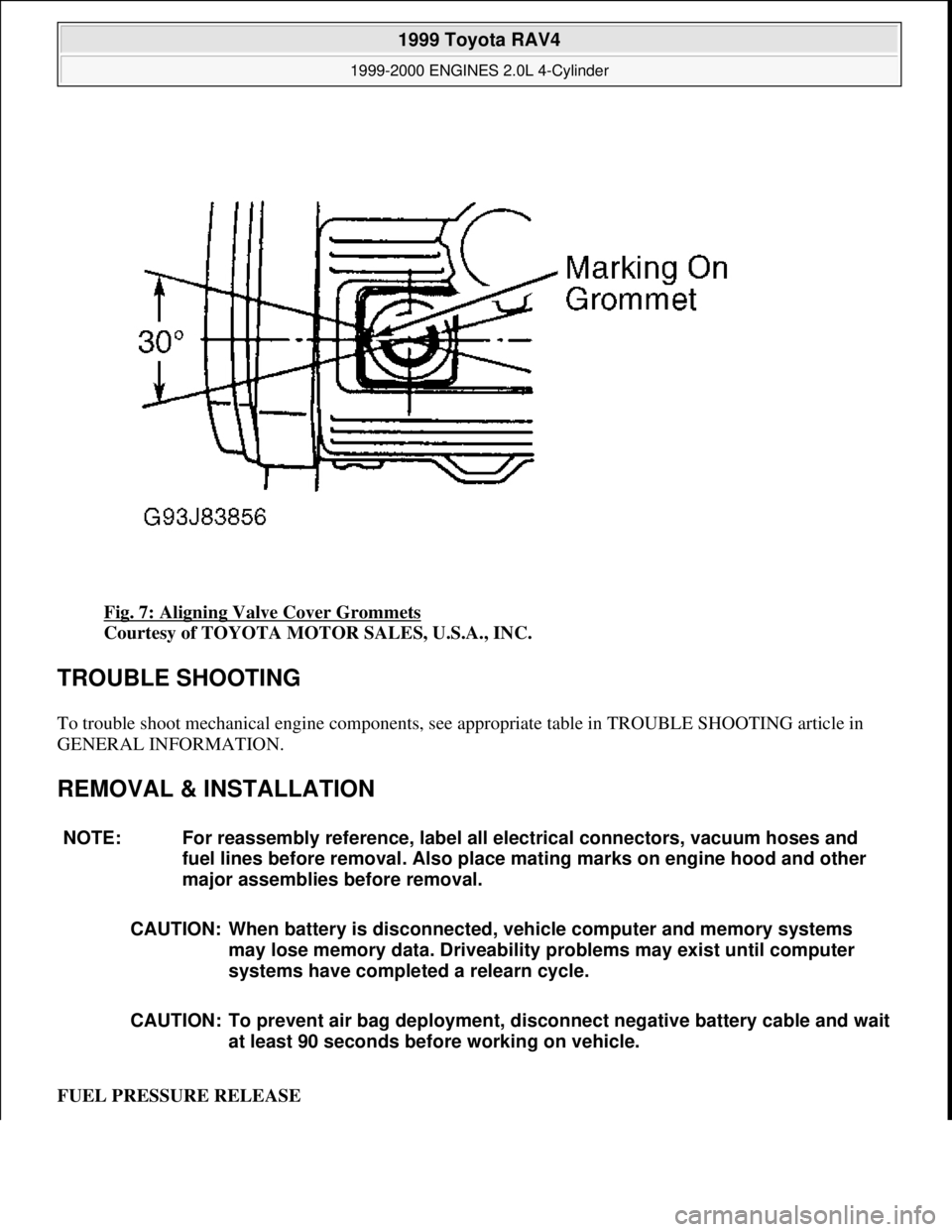
Fig. 7: Aligning Valve Cover Grommets
Courtesy of TOYOTA MOTOR SALES, U.S.A., INC.
TROUBLE SHOOTING
To trouble shoot mechanical engine components, see appropriate table in TROUBLE SHOOTING article in
GENERAL INFORMATION.
REMOVAL & INSTALLATION
FUEL PRESSURE RELEASE
NOTE: For reassembly reference, label all electrical connectors, vacuum hoses and
fuel lines before removal. Also place mating marks on engine hood and other
major assemblies before removal.
CAUTION: When battery is disconnected, vehicle computer and memory systems
may lose memory data. Driveability problems may exist until computer
systems have completed a relearn cycle.
CAUTION: To prevent air bag deployment, disconnect negative battery cable and wait
at least 90 seconds before working on vehicle.
1999 Toyota RAV4
1999-2000 ENGINES 2.0L 4-Cylinder
Microsoft
Sunday, November 22, 2009 10:22:26 AMPage 9 © 2005 Mitchell Repair Information Company, LLC.
Page 694 of 1632
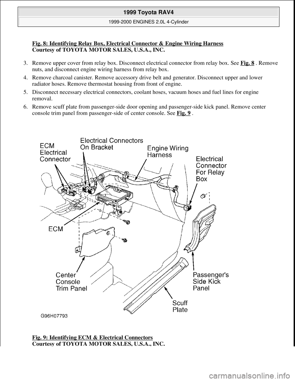
Fig. 8: Identifying Relay Box, Electrical Connector & Engine Wiring Harness
Courtesy of TOYOTA MOTOR SALES, U.S.A., INC.
3. Remove upper cover from relay box. Disconnect electrical connector from relay box. See Fig. 8
. Remove
nuts, and disconnect engine wiring harness from relay box.
4. Remove charcoal canister. Remove accessory drive belt and generator. Disconnect upper and lower
radiator hoses. Remove thermostat housing from front of engine.
5. Disconnect necessary electrical connectors, coolant hoses, vacuum hoses and fuel lines for engine
removal.
6. Remove scuff plate from passenger-side door opening and passenger-side kick panel. Remove center
console trim panel from passenger-side of center console. See Fig. 9
.
Fig. 9: Identifying ECM & Electrical Connectors
Courtesy of TOYOTA MOTOR SALES, U.S.A., INC.
1999 Toyota RAV4
1999-2000 ENGINES 2.0L 4-Cylinder
Microsoft
Sunday, November 22, 2009 10:22:26 AMPage 11 © 2005 Mitchell Repair Information Company, LLC.