change time TOYOTA RAV4 1996 Service Repair Manual
[x] Cancel search | Manufacturer: TOYOTA, Model Year: 1996, Model line: RAV4, Model: TOYOTA RAV4 1996Pages: 1632, PDF Size: 41.64 MB
Page 15 of 1632
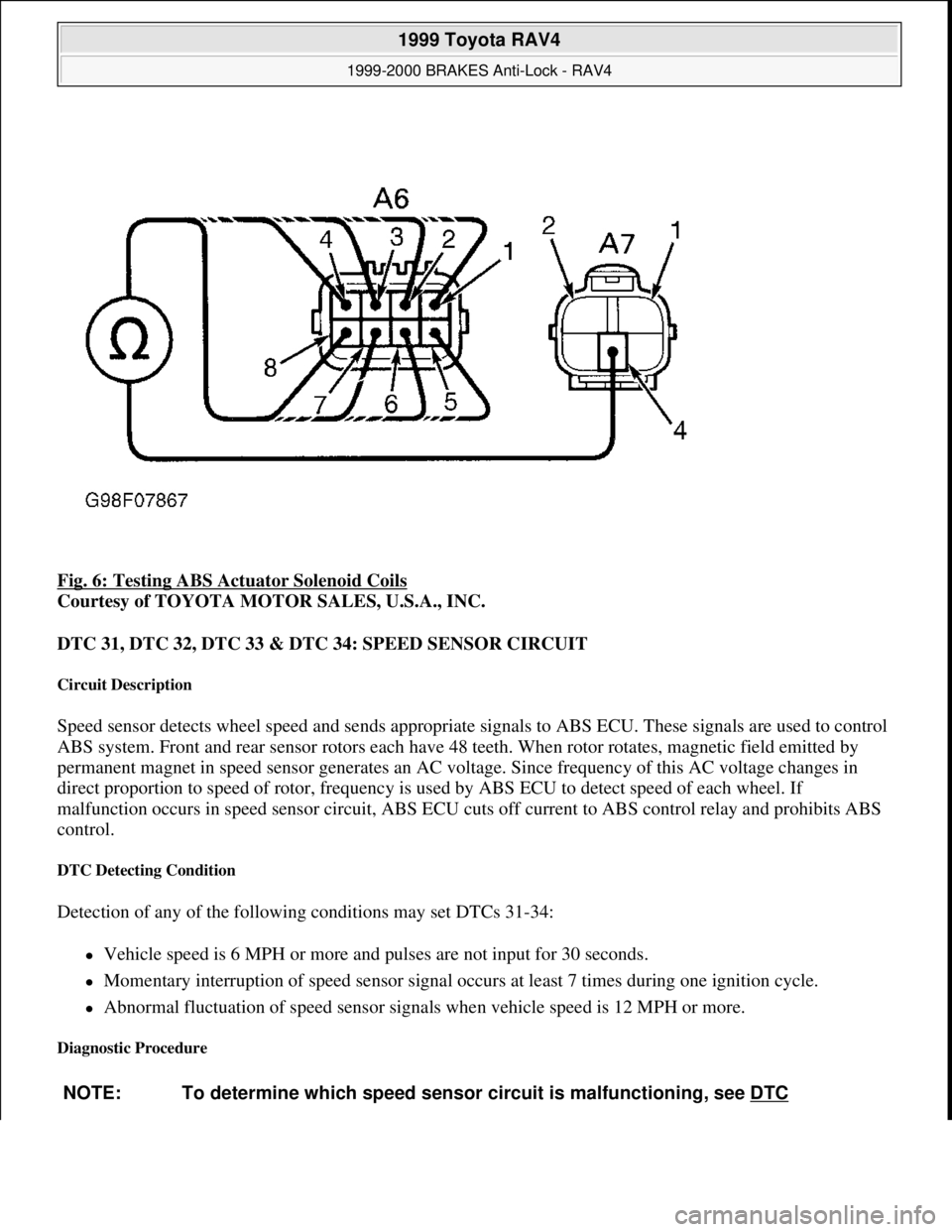
Fig. 6: Testing ABS Actuator Solenoid Coils
Courtesy of TOYOTA MOTOR SALES, U.S.A., INC.
DTC 31, DTC 32, DTC 33 & DTC 34: SPEED SENSOR CIRCUIT
Circuit Description
Speed sensor detects wheel speed and sends appropriate signals to ABS ECU. These signals are used to control
ABS system. Front and rear sensor rotors each have 48 teeth. When rotor rotates, magnetic field emitted by
permanent magnet in speed sensor generates an AC voltage. Since frequency of this AC voltage changes in
direct proportion to speed of rotor, frequency is used by ABS ECU to detect speed of each wheel. If
malfunction occurs in speed sensor circuit, ABS ECU cuts off current to ABS control relay and prohibits ABS
control.
DTC Detecting Condition
Detection of any of the following conditions may set DTCs 31-34:
Vehicle speed is 6 MPH or more and pulses are not input for 30 seconds.
Momentary interruption of speed sensor signal occurs at least 7 times during one ignition cycle.
Abnormal fluctuation of speed sensor signals when vehicle speed is 12 MPH or more.
Diagnostic Procedure
NOTE: To determine which speed sensor circuit is malfunctioning, see DTC
1999 Toyota RAV4
1999-2000 BRAKES Anti-Lock - RAV4
Microsoft
Sunday, November 22, 2009 10:06:17 AMPage 15 © 2005 Mitchell Repair Information Company, LLC.
Page 17 of 1632
DTC Detecting Condition
Detection of the following condition may set DTC 41:
At vehicle speed of about 2 MPH or more, if voltage at ABS ECU terminal IG1 is less than 9.5 volts for
10 seconds or more, DTC 41 may set.
Diagnostic Procedure
1. Check charging system voltage. If voltage is 10-14 volts, system is okay. Go to next step. If voltage is not
10-14 volts, repair charging system. Ensure system fuses are okay.
2. Turn ignition off. Remove ABS ECU. Do not disconnect electrical connectors. Turn ignition switch to
ON position. Measure voltage between terminals IG1 and GND at ABS ECU harness connector. See Fig.
3 . If voltage is 10-14 volts, turn ignition off. Condition may be intermittent. Check ABS ECU connectors
for poor connection or damage. Repair as necessary. If connectors are okay, replace ABS ECU. If voltage
is not as specified, go to next step.
3. Measure resistance between ground and GND terminals at ABS ECU harness connector. See Fig. 3
. If
resistance is one ohm or less, go to next step. If resistance is more than one ohm, repair ground circuit
wiring. See WIRING DIAGRAMS
.
4. Remove ECU-IG fuse from instrument panel junction block. If fuse is blown, check for short circuit in all
wiring harnesses and components connected to ECU-IG fuse (ECM, A/C, cruise control, deceleration
sensor, combination meter, sun roof, shift lock, transmission pattern select switch). See WIRING
DIAGRAMS . Repair as necessary. If fuse is not blown, check for open circuit in wiring harness between
battery and ABS ECU. Repair as necessary.
DTC 43 & DTC 45: DECELERATION SENSOR MALFUNCTION (4WD MODELS ONLY)
DTC Detecting Conditions
Detection of the following conditions may set DTCs 43 or 45:
On 2-door models, if output voltage from deceleration sensor does not change for 16 consecutive times or
more when vehicle speed is decreased from 19 MPH to zero MPH, DTC 43 will set.
On 4-door models, after battery cables are connected, if input from deceleration sensor does not change at
one cycle (zero MPH to 19 MPH or more, then back to zero) for 16 consecutive times, DTC 43 will set.
When brake pedal is not depressed at vehicle speed of 3 MPH or more, and forward and backward force
(force of more than 0.4 "G") is detected for 30 seconds or more, DTC 43 will set.
On 2-door models, at vehicle speed of 19 MPH or more, if deceleration sensor output and vehicle
acceleration from wheel speed remains abnormally different for one minute or more, DTC 45 will set.
Diagnostic Procedure
1. Check deceleration sensor. See DECELERATION SENSOR CHECK under COMPONENT TESTS.
Replace sensor as necessary. If sensor is okay, go to next step.
2. Check for open or short circuit in wiring harness between deceleration sensor and ABS ECU. See
WIRING DIAGRAMS
. Repair as necessary. If wiring harness is okay, replace ABS ECU.
1999 Toyota RAV4
1999-2000 BRAKES Anti-Lock - RAV4
Microsoft
Sunday, November 22, 2009 10:06:17 AMPage 17 © 2005 Mitchell Repair Information Company, LLC.
Page 26 of 1632
1. Check charging system voltage. Ensure 10-14 volts is present. If charging system voltage is okay, go to
next step. If charging system voltage is not okay, check and repair charging system.
2. Turn ignition switch to ON position. Ensure ABS warning light comes on, then goes out after 3 seconds.
If ABS warning light does not illuminate, check fuse, bulb, and wiring harness. See ABS WARNING
LIGHT under DIAGNOSIS & TESTING. Turn ignition off.
3. Using a jumper wire, jumper terminals Ts and E
1 of DLC1. DLC1 is located in engine compartment on
left side of engine. See Fig. 2
. Ensure ABS warning light blinks 4 times per second. If ABS light does
not blink, go to ABS WARNING LIGHT
under DIAGNOSIS & TESTING. If ABS warning light
blinks, go to next step.
4. Using a floor jack, slowly jack up rear of vehicle. On vehicles with 215/70R16 tires, raise vehicle to a
height of 25.59-27.95" (650-710 mm). On vehicles with 235/60R16 tires, raise vehicle to a height of
26.38-28.74" (670-730 mm). If ABS warning light illuminates at specified height, check deceleration
sensor installation. If installation is okay, replace deceleration sensor. Lower vehicle.
5. Using a floor jack, slowly jack up front of vehicle. On vehicles with 215/70R16 tires, raise vehicle to a
height of 21.20-23.56" (550-610 mm). On vehicles with 235/60R16 tires, raise vehicle to a height of
22.44-24.80" (570-630 mm). If ABS warning light illuminates at specified height, check deceleration
sensor installation. If installation is okay, replace deceleration sensor. Lower vehicle.
6. Drive vehicle straight ahead at speed of 13 MPH or more. Lightly depress brake pedal. Ensure ABS
warning light pattern is normal (light blinks 4 times per second).
7. While driving vehicle straight ahead at speed of 13 MPH or more, moderately depress brake pedal.
Ensure ABS warning light illuminates in a solid pattern (light does not blink) while braking.
8. While driving vehicle straight ahead at speed of 13 MPH or more, firmly depress brake pedal. Ensure
ABS warning light illumination pattern changes from a solid pattern (light does not blink) to a normal
pattern (light blinks 4 times per second), then back to a solid pattern while braking.
9. If ABS warning light does not illuminate as described in steps 6 -8 , check deceleration sensor
installation. If installation is okay, replace deceleration sensor. Stop vehicle and turn ignition off. Remove
jumper wire from DLC1.
REMOVAL & INSTALLATION
ACTUATOR
Removal & Installation
Turn ignition off. Disconnect brakelines attached to actuator. Remove power steering hose retaining bracket
bolt and power steering reservoir. Disconnect actuator electrical connectors. Remove bolts, nuts and washers.
Remove actuator assembly. Remove actuator from actuator bracket. Remove cushions and holders from NOTE: When measuring vehicle height in following steps, measure at center of
lower body of vehicle.
WARNING:Hydraulic system may be under high pressure. Use caution when opening
hydraulic system.
1999 Toyota RAV4
1999-2000 BRAKES Anti-Lock - RAV4
Microsoft
Sunday, November 22, 2009 10:06:17 AMPage 26 © 2005 Mitchell Repair Information Company, LLC.
Page 344 of 1632
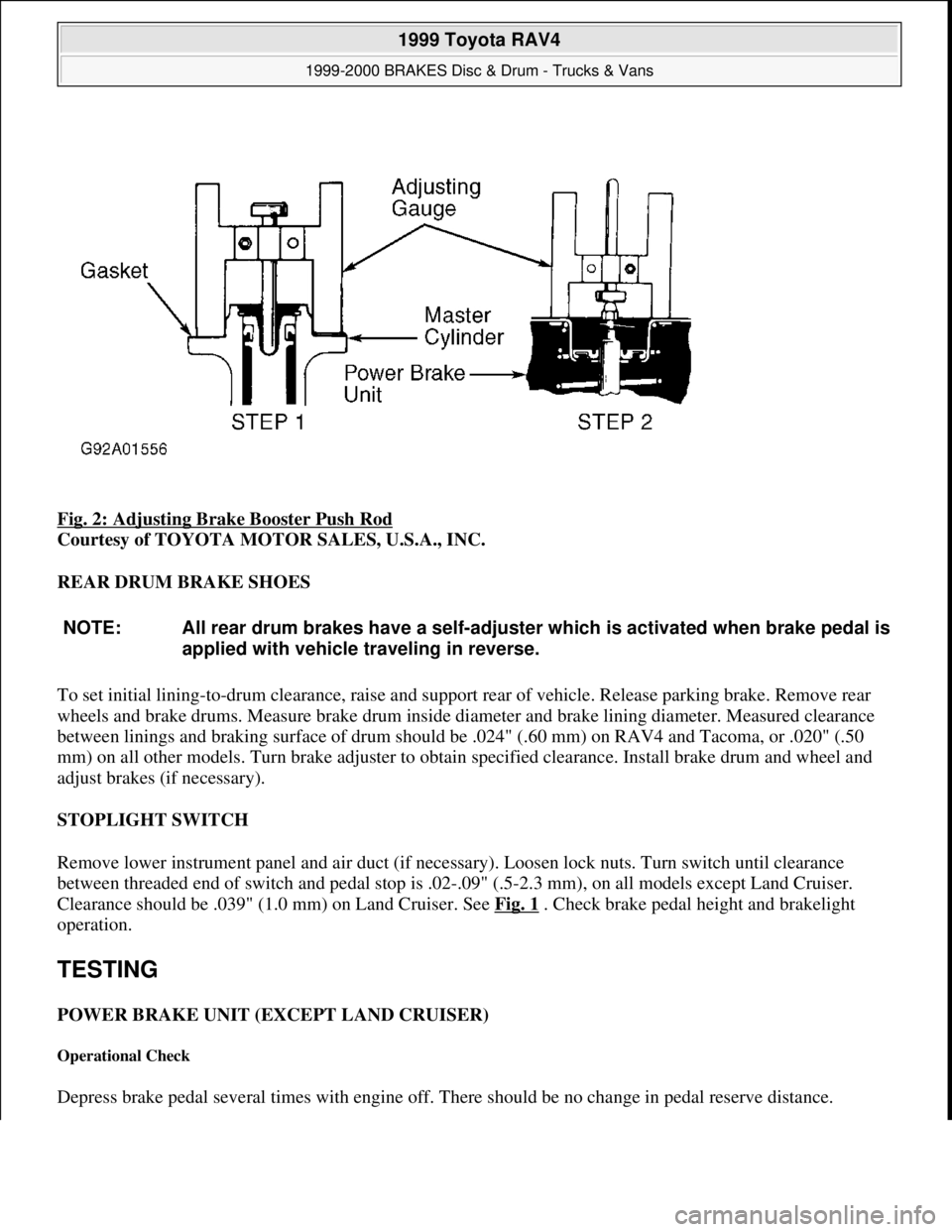
Fig. 2: Adjusting Brake Booster Push Rod
Courtesy of TOYOTA MOTOR SALES, U.S.A., INC.
REAR DRUM BRAKE SHOES
To set initial lining-to-drum clearance, raise and support rear of vehicle. Release parking brake. Remove rear
wheels and brake drums. Measure brake drum inside diameter and brake lining diameter. Measured clearance
between linings and braking surface of drum should be .024" (.60 mm) on RAV4 and Tacoma, or .020" (.50
mm) on all other models. Turn brake adjuster to obtain specified clearance. Install brake drum and wheel and
adjust brakes (if necessary).
STOPLIGHT SWITCH
Remove lower instrument panel and air duct (if necessary). Loosen lock nuts. Turn switch until clearance
between threaded end of switch and pedal stop is .02-.09" (.5-2.3 mm), on all models except Land Cruiser.
Clearance should be .039" (1.0 mm) on Land Cruiser. See Fig. 1
. Check brake pedal height and brakelight
operation.
TESTING
POWER BRAKE UNIT (EXCEPT LAND CRUISER)
Operational Check
Depress brake pedal several times with engine off. There should be no change in pedal reserve distance.
NOTE: All rear drum brakes have a self-adjuster which is activated when brake pedal is
applied with vehicle traveling in reverse.
1999 Toyota RAV4
1999-2000 BRAKES Disc & Drum - Trucks & Vans
Microsoft
Sunday, November 22, 2009 10:07:28 AMPage 5 © 2005 Mitchell Repair Information Company, LLC.
Page 353 of 1632
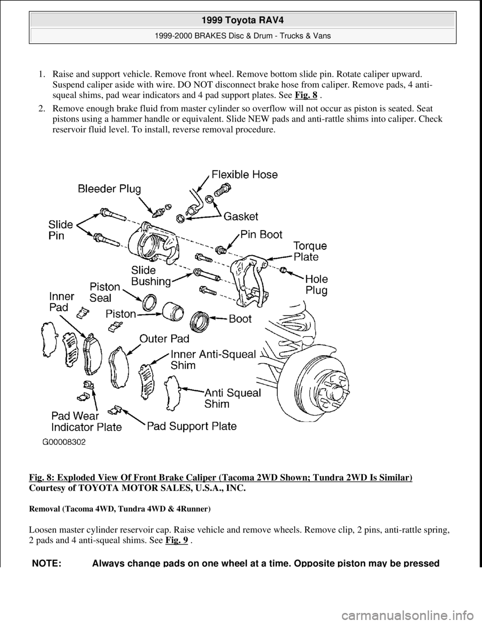
1. Raise and support vehicle. Remove front wheel. Remove bottom slide pin. Rotate caliper upward.
Suspend caliper aside with wire. DO NOT disconnect brake hose from caliper. Remove pads, 4 anti-
squeal shims, pad wear indicators and 4 pad support plates. See Fig. 8
.
2. Remove enough brake fluid from master cylinder so overflow will not occur as piston is seated. Seat
pistons using a hammer handle or equivalent. Slide NEW pads and anti-rattle shims into caliper. Check
reservoir fluid level. To install, reverse removal procedure.
Fig. 8: Exploded View Of Front Brake Caliper (Tacoma 2WD Shown; Tundra 2WD Is Similar)
Courtesy of TOYOTA MOTOR SALES, U.S.A., INC.
Removal (Tacoma 4WD, Tundra 4WD & 4Runner)
Loosen master cylinder reservoir cap. Raise vehicle and remove wheels. Remove clip, 2 pins, anti-rattle spring,
2 pads and 4 anti-squeal shims. See Fig. 9
.
NOTE: Always change pads on one wheel at a time. Opposite piston may be pressed
1999 Toyota RAV4
1999-2000 BRAKES Disc & Drum - Trucks & Vans
Microsoft
Sunday, November 22, 2009 10:07:28 AMPage 14 © 2005 Mitchell Repair Information Company, LLC.
Page 533 of 1632
Perform ELECTRONICALLY CONTROLLED TRANSMISSION (ECT) CIRCUIT test under
SYSTEM TESTS.
Replace cruise control ECU with a known-good ECU and retest. If symptom is no longer present, replace
ECU.
DTC Memory Is Erased
Replace cruise control ECU with a known-good ECU and retest. If symptom is no longer present, replace ECU.
DTC Not Output, Or DTC Output When It Should Not Be
Check the following components and/or circuits:
Perform DIAGNOSTIC CIRCUIT test under SYSTEM TESTS.
Replace cruise control ECU with a known-good ECU and retest. If symptom is no longer present, replace
ECU.
CRUISE Control Indicator Light Stays On Or Fails To Turn On
Check the following components and/or circuits:
Perform CRUISE CONTROL INDICATOR LIGHT CIRCUIT test under SYSTEM TESTS.
Replace cruise control ECU with a known-good ECU and retest. If symptom is no longer present, replace
ECU.
COMPONENT TESTS
VEHICLE SPEED SENSOR
1. Remove vehicle speed sensor from transaxle. See Fig. 1
. Using jumper wires, connect positive battery
terminal to vehicle speed sensor terminal No. 1 (Red/Blue wire) and negative battery terminal to terminal
No. 2 (Blue/Black wire).
2. Connect voltmeter positive lead to terminal No. 3 (Red/Yellow wire) and negative lead to terminal No. 2
(Blue/Black wire). See Fig. 5
. Rotate vehicle speed sensor shaft and ensure voltage changes from 0-11
volts or more 4 times per shaft revolution. Replace vehicle speed sensor as necessary.
SYSTEM TESTS
CRUISE CONTROL SWITCH CIRCUIT
1. Perform SET/COAST, RES/ACC, and CANCEL SWITCHES tests under CRUISE CONTROL
NOTE: To identify cruise control ECU connector terminals, see Fig. 6 . To help identify
all other cruise control related connector terminals and wire colors, see WIRING
DIAGRAMS .
1999 Toyota RAV4
1999 ACCESSORIES & EQUIPMENT Cruise Control Systems - RAV4
Microsoft
Sunday, November 22, 2009 10:52:01 AMPage 9 © 2005 Mitchell Repair Information Company, LLC.
Page 544 of 1632
1. Perform VEHICLE SPEED SENSOR test under CRUISE CONTROL FUNCTION TEST under
TROUBLE SHOOTING. If speed sensor input signals are not as specified, go to next step. If speed
sensor input signals are as specified, replace cruise control ECU and retest system.
2. Check speedometer circuit. See appropriate INSTRUMENT PANELS article. If speedometer circuit is
okay, go to next step. If speedometer circuit is not okay, repair wiring harness, connector or instrument
cluster as necessary. Retest system.
3. Check wiring harness and connectors between cruise control ECU, vehicle speed sensor and instrument
cluster. Repair as necessary and retest system. If wiring harness and connectors are okay, go to next step.
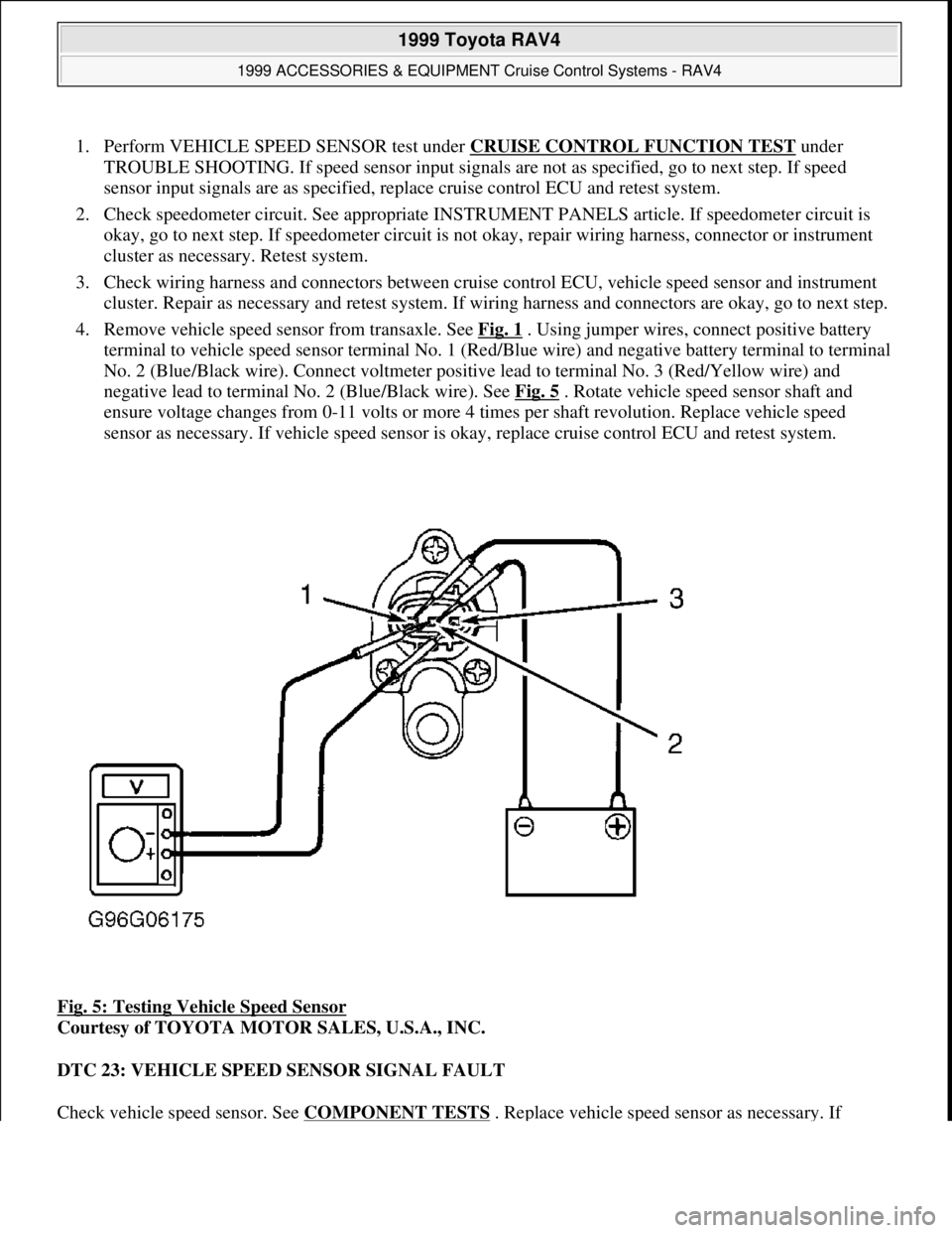
4. Remove vehicle speed sensor from transaxle. See Fig. 1
. Using jumper wires, connect positive battery
terminal to vehicle speed sensor terminal No. 1 (Red/Blue wire) and negative battery terminal to terminal
No. 2 (Blue/Black wire). Connect voltmeter positive lead to terminal No. 3 (Red/Yellow wire) and
negative lead to terminal No. 2 (Blue/Black wire). See Fig. 5
. Rotate vehicle speed sensor shaft and
ensure voltage changes from 0-11 volts or more 4 times per shaft revolution. Replace vehicle speed
sensor as necessary. If vehicle speed sensor is okay, replace cruise control ECU and retest system.
Fig. 5: Testing Vehicle Speed Sensor
Courtesy of TOYOTA MOTOR SALES, U.S.A., INC.
DTC 23: VEHICLE SPEED SENSOR SIGNAL FAULT
Check vehicle speed sensor. See COMPONENT TESTS
. Replace vehicle speed sensor as necessary. If
1999 Toyota RAV4
1999 ACCESSORIES & EQUIPMENT Cruise Control Systems - RAV4
Microsoft
Sunday, November 22, 2009 10:52:01 AMPage 20 © 2005 Mitchell Repair Information Company, LLC.
Page 988 of 1632
2. Push side gear and pinions to right side of case. Measure side gear backlash. Select thrust washer which
will ensure backlash is within limits. Thrust washers are available in thicknesses of .031" (.80 mm)
to .055" (1.40 mm), in .004" (.10 mm) increments.
3. Install vehicle speed sensor drive gear. Align match marks on differential cases and carefully tap together.
Install and tighten attaching screws. Clean contact surface of differential case and threads of ring gear.
Heat ring gear in water to 212°F (100°C). Quickly clean ring gear contact surface with solvent, then
install on differential case.
4. Allow ring gear to cool. Tighten ring gear bolts to 91 ft. lbs. (124 N.m). Press NEW bearings onto
differential cases. Adjust output shaft bearing preload. See OUTPUT SHAFT BEARING PRELOAD
under TRANSAXLE REASSEMBLY. Install differential case assembly into transaxle case half. Install
output shaft assembly. Install transmission case half. Tighten bolts.
5. Install output shaft bearing outer race. Install shim. Install rear bearing retainer, and tighten bolts. Install
NEW lock nut onto output shaft. Rotate output shaft 2-3 times to set bearings. Install torque wrench, and
measure side bearing preload. If preload is not 1.6-3.0 INCH lbs. (1.8-3.5 kg) for NEW bearings, or 1.0-.9
INCH lbs. (1.1-2.2 kg) for used bearings, select appropriate adjusting shim. Adjusting shims are available
in thicknesses of .079" (2.0 mm) to .112" (2.85 mm) in .002" (.05 mm) increments. Shims are stamped
"1"-"9", and "A"-"H".
Disassembly (4WD Models)
1. Remove No. 2 differential case. Match mark differential case and ring gear. Remove ring gear. Remove
No. 2 differential side gear thrust washer and conical spring washer. See Fig. 14
.
2. Remove front differential case assembly. Remove front differential side gear and thrust washer. Remove
snap ring and spacer.
Remove front differential pinion shafts, No. 2 front pinion shaft, shaft holder, pinions, pinion thrust
washers, front differential side gear and front differential thrust washer. Remove snap ring, spacer and
vehicle speed sensor drive gear. Remove tapered roller bearing.
3. From No. 1 differential case, remove pinion shafts, shaft holder, pinions and thrust washers, differential
side gear subassembly, conical spring washer and side gear thrust washer. Remove tapered roller bearing.
See Fig. 14
. NOTE: Total preload will change approximately 1.7 lbs. (1 kg) for every .002" (.05
mm) change in adjusting shim thickness.
NOTE: Wrap vinyl tape around case to prevent damage.
1999 Toyota RAV4
1999 MANUAL TRANSMISSIONS Toyota E250 & E250F 5-Speed Overhaul
Microsoft
Sunday, November 22, 2009 10:48:07 AMPage 18 © 2005 Mitchell Repair Information Company, LLC.
Page 1454 of 1632
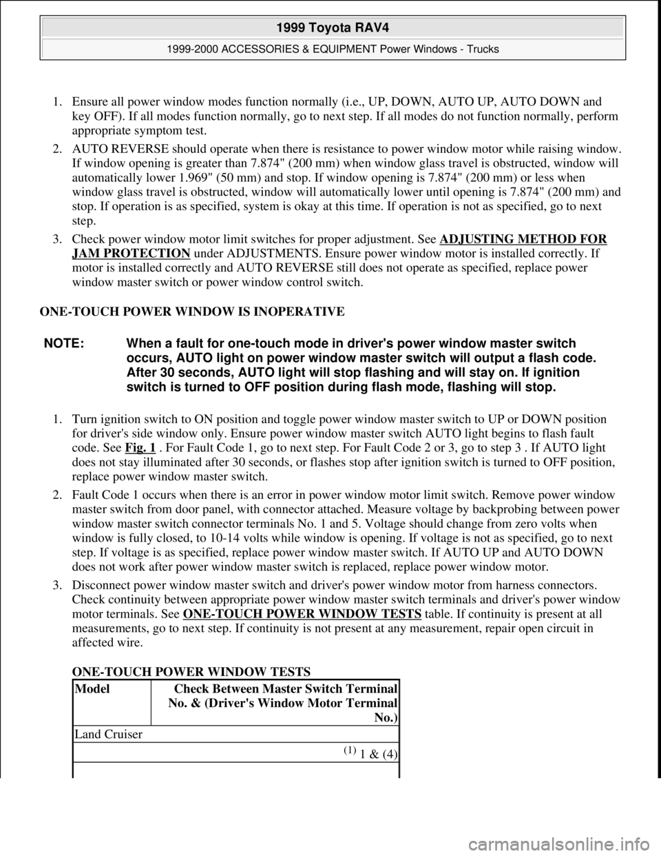
1. Ensure all power window modes function normally (i.e., UP, DOWN, AUTO UP, AUTO DOWN and
key OFF). If all modes function normally, go to next step. If all modes do not function normally, perform
appropriate symptom test.
2. AUTO REVERSE should operate when there is resistance to power window motor while raising window.
If window opening is greater than 7.874" (200 mm) when window glass travel is obstructed, window will
automatically lower 1.969" (50 mm) and stop. If window opening is 7.874" (200 mm) or less when
window glass travel is obstructed, window will automatically lower until opening is 7.874" (200 mm) and
stop. If operation is as specified, system is okay at this time. If operation is not as specified, go to next
step.
3. Check power window motor limit switches for proper adjustment. See ADJUSTING METHOD FOR
JAM PROTECTION under ADJUSTMENTS. Ensure power window motor is installed correctly. If
motor is installed correctly and AUTO REVERSE still does not operate as specified, replace power
window master switch or power window control switch.
ONE-TOUCH POWER WINDOW IS INOPERATIVE
1. Turn ignition switch to ON position and toggle power window master switch to UP or DOWN position
for driver's side window only. Ensure power window master switch AUTO light begins to flash fault
code. See Fig. 1
. For Fault Code 1, go to next step. For Fault Code 2 or 3, go to step 3 . If AUTO light
does not stay illuminated after 30 seconds, or flashes stop after ignition switch is turned to OFF position,
replace power window master switch.
2. Fault Code 1 occurs when there is an error in power window motor limit switch. Remove power window
master switch from door panel, with connector attached. Measure voltage by backprobing between power
window master switch connector terminals No. 1 and 5. Voltage should change from zero volts when
window is fully closed, to 10-14 volts while window is opening. If voltage is not as specified, go to next
step. If voltage is as specified, replace power window master switch. If AUTO UP and AUTO DOWN
does not work after power window master switch is replaced, replace power window motor.
3. Disconnect power window master switch and driver's power window motor from harness connectors.
Check continuity between appropriate power window master switch terminals and driver's power window
motor terminals. See ONE
-TOUCH POWER WINDOW TESTS table. If continuity is present at all
measurements, go to next step. If continuity is not present at any measurement, repair open circuit in
affected wire.
ONE-TOUCH POWER WINDOW TESTS NOTE: When a fault for one-touch mode in driver's power window master switch
occurs, AUTO light on power window master switch will output a flash code.
After 30 seconds, AUTO light will stop flashing and will stay on. If ignition
switch is turned to OFF position during flash mode, flashing will stop.
ModelCheck Between Master Switch Terminal
No. & (Driver's Window Motor Terminal
No.)
Land Cruiser
(1) 1 & (4)
1999 Toyota RAV4
1999-2000 ACCESSORIES & EQUIPMENT Power Windows - Trucks
Microsoft
Sunday, November 22, 2009 10:59:35 AMPage 2 © 2005 Mitchell Repair Information Company, LLC.
Page 1512 of 1632
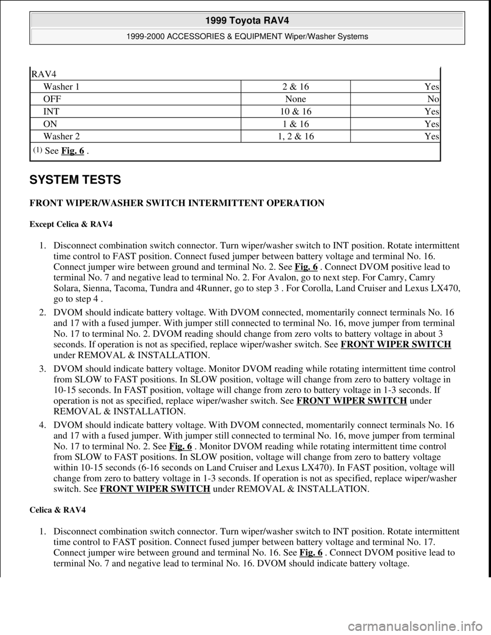
SYSTEM TESTS
FRONT WIPER/WASHER SWITCH INTERMITTENT OPERATION
Except Celica & RAV4
1. Disconnect combination switch connector. Turn wiper/washer switch to INT position. Rotate intermittent
time control to FAST position. Connect fused jumper between battery voltage and terminal No. 16.
Connect jumper wire between ground and terminal No. 2. See Fig. 6
. Connect DVOM positive lead to
terminal No. 7 and negative lead to terminal No. 2. For Avalon, go to next step. For Camry, Camry
Solara, Sienna, Tacoma, Tundra and 4Runner, go to step 3 . For Corolla, Land Cruiser and Lexus LX470,
go to step 4 .
2. DVOM should indicate battery voltage. With DVOM connected, momentarily connect terminals No. 16
and 17 with a fused jumper. With jumper still connected to terminal No. 16, move jumper from terminal
No. 17 to terminal No. 2. DVOM reading should change from zero volts to battery voltage in about 3
seconds. If operation is not as specified, replace wiper/washer switch. See FRONT WIPER SWITCH
under REMOVAL & INSTALLATION.
3. DVOM should indicate battery voltage. Monitor DVOM reading while rotating intermittent time control
from SLOW to FAST positions. In SLOW position, voltage will change from zero to battery voltage in
10-15 seconds. In FAST position, voltage will change from zero to battery voltage in 1-3 seconds. If
operation is not as specified, replace wiper/washer switch. See FRONT WIPER SWITCH
under
REMOVAL & INSTALLATION.
4. DVOM should indicate battery voltage. With DVOM connected, momentarily connect terminals No. 16
and 17 with a fused jumper. With jumper still connected to terminal No. 16, move jumper from terminal
No. 17 to terminal No. 2. See Fig. 6
. Monitor DVOM reading while rotating intermittent time control
from SLOW to FAST positions. In SLOW position, voltage will change from zero to battery voltage
within 10-15 seconds (6-16 seconds on Land Cruiser and Lexus LX470). In FAST position, voltage will
change from zero to battery voltage in 1-3 seconds. If operation is not as specified, replace wiper/washer
switch. See FRONT WIPER SWITCH
under REMOVAL & INSTALLATION.
Celica & RAV4
1. Disconnect combination switch connector. Turn wiper/washer switch to INT position. Rotate intermittent
time control to FAST position. Connect fused jumper between battery voltage and terminal No. 17.
Connect jumper wire between ground and terminal No. 16. See Fig. 6
. Connect DVOM positive lead to
terminal No. 7 and ne
gative lead to terminal No. 16. DVOM should indicate battery voltage.
RAV4
Washer 12 & 16Yes
OFFNoneNo
INT10 & 16Yes
ON1 & 16Yes
Washer 21, 2 & 16Yes
(1)See Fig. 6 .
1999 Toyota RAV4
1999-2000 ACCESSORIES & EQUIPMENT Wiper/Washer Systems
Microsoft
Sunday, November 22, 2009 11:01:20 AMPage 17 © 2005 Mitchell Repair Information Company, LLC.