lights TOYOTA RAV4 1996 Service Repair Manual
[x] Cancel search | Manufacturer: TOYOTA, Model Year: 1996, Model line: RAV4, Model: TOYOTA RAV4 1996Pages: 1632, PDF Size: 41.64 MB
Page 9 of 1632
SYMPTOM TESTS
ABS LIGHT ON: ABS ECU MALFUNCTION
Circuit Description
This circuit is the power source for ABS ECU and actuator.
DTC Detecting Condition
If voltage at ABS ECU terminal IG1 remains more than 17 volts, this DTC will set. If a malfunction occurs in
power source circuit, ABS ECU cuts off current to ABS control relay and prohibits ABS control.
Diagnostic Procedure
1. Retrieve DTCs. See RETRIEVING DTCS under DIAGNOSIS & TESTING. If DTC is output using
ABS warning light, perform appropriate test under DIAGNOSTIC TESTS
. If ABS warning light does
not operate normally, go to next step. If ABS warning light operates normally (lights blink 2 times per
second and no DTCs are present), check ABS control (solenoid) relay. See SOLENOID RELAY
SECTION under ABS CONTROL RELAY under COMPONENT TESTS. Check for short circuit in
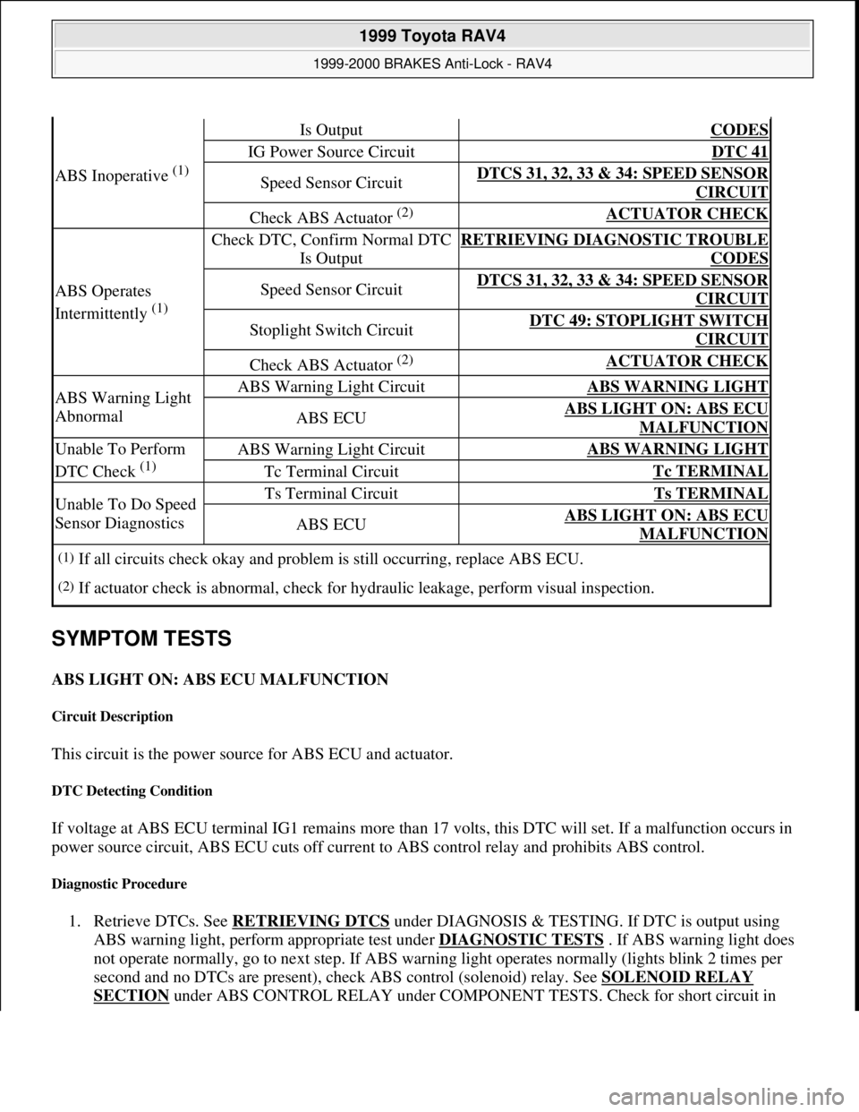
ABS Inoperative (1)
Is OutputCODES
IG Power Source CircuitDTC 41
Speed Sensor CircuitDTCS 31, 32, 33 & 34: SPEED SENSOR
CIRCUIT
Check ABS Actuator (2) ACTUATOR CHECK
ABS Operates
Intermittently
(1)
Check DTC, Confirm Normal DTC
Is OutputRETRIEVING DIAGNOSTIC TROUBLE
CODES
Speed Sensor CircuitDTCS 31, 32, 33 & 34: SPEED SENSOR
CIRCUIT
Stoplight Switch CircuitDTC 49: STOPLIGHT SWITCH
CIRCUIT
Check ABS Actuator (2) ACTUATOR CHECK
ABS Warning Light
AbnormalABS Warning Light CircuitABS WARNING LIGHT
ABS ECUABS LIGHT ON: ABS ECU
MALFUNCTION
Unable To Perform
DTC Check
(1)
ABS Warning Light CircuitABS WARNING LIGHT
Tc Terminal CircuitTc TERMINAL
Unable To Do Speed
Sensor DiagnosticsTs Terminal CircuitTs TERMINAL
ABS ECUABS LIGHT ON: ABS ECU
MALFUNCTION
(1)If all circuits check okay and problem is still occurring, replace ABS ECU.
(2)If actuator check is abnormal, check for hydraulic leakage, perform visual inspection.
1999 Toyota RAV4
1999-2000 BRAKES Anti-Lock - RAV4
Microsoft
Sunday, November 22, 2009 10:06:17 AMPage 9 © 2005 Mitchell Repair Information Company, LLC.
Page 19 of 1632
Diagnostic Procedure
1. Depress brake pedal and ensure brakelights illuminate. If brakelights illuminate, go to next step. If
brakelights do not illuminate, check stoplight switch adjustment. See STOPLIGHT SWITCH
under
ADJUSTMENTS. If stoplight switch adjustment is okay, locate and repair fault in stoplight circuit. See
WIRING DIAGRAMS
.
2. Turn ignition off. Remove ABS ECU. Do not disconnect electrical connectors. Measure voltage between
ground and terminal STP at ABS ECU harness connector when brake pedal is depressed. See Fig. 3
. If
voltage is 8-14 volts, stoplight switch circuit is okay at this time. If voltage is not 8-14 volts, go to next
step.
3. Check for open circuit in wiring harness between stoplight switch and ABS ECU. Repair as necessary.
See WIRING DIAGRAMS
. If wiring harness is okay, replace ABS ECU.
DTC 51: ABS PUMP MOTOR LOCKED
Circuit Description
If malfunction occurs in ABS pump motor, ABS ECU cuts off current to ABS control relay and prohibits ABS
control.
DTC Detection Condition
Detection of the following condition may set DTC 51:
ABS actuator pump motor is not operating properly during initial check.
Diagnostic Procedure
Disconnect ABS actuator connector A7. Connect jumper wires between battery positive terminal and actuator
terminal A7-2, and battery negative terminal to terminal A7-1. See Fig. 6
. Ensure pump motor operates. If
pump motor operates, check for open circuit in wiring harness between ABS control relay, actuator and ABS
ECU. Repair as necessary. See WIRING DIAGRAMS
. If pump motor does not operate, replace ABS
actuator.
COMPONENT TESTS
ABS CONTROL RELAY
Solenoid Relay Section
1. Check continuity between specified ABS control relay terminals. See Fig. 7 . Continuity should exist
between ABS control relay terminals A9-5 and A9-6. Continuity should not exist between terminals A9-2 NOTE: ABS control relay has both ABS solenoid relay and ABS motor relay integrated
into one component. Replace complete ABS control relay if either solenoid or
motor section fails.
1999 Toyota RAV4
1999-2000 BRAKES Anti-Lock - RAV4
Microsoft
Sunday, November 22, 2009 10:06:17 AMPage 19 © 2005 Mitchell Repair Information Company, LLC.
Page 56 of 1632
3. With squib circuit connector disconnected, insert paper into female terminal, sliding it under shorting bar
spring. This lifts the spring, breaking the circuit and allowing the test procedure to be performed as
specified.
TESTING - DIAGNOSTIC
NO CODES - SOURCE VOLTAGE DROP
1. Disconnect negative battery cable. Wait at least 90 seconds. Remove steering wheel pad. See
STEERING WHEEL PAD & SPIRAL CABLE
under REMOVAL & INSTALLATION. Disconnect
passenger-side air bag harness connector, accessible through finish plate in glove box. See Fig. 2
.
Disconnect air bag sensor assembly connector.
2. Reconnect negative battery cable. Turn ignition switch to ON position. Measure voltage between ground
and terminals IG2 and ACC of air bag sensor connector. See Fig. 13
. Operate electrical components
(defogger, wiper, headlights, heater blower, etc.). If voltage is 8-14 volts, go to next step. If voltage is not
8-14 volts, check harness between battery and air bag sensor assembly and check battery and charging
system.
3. Turn ignition switch to LOCK position. Connect steering wheel pad connector. Connect passenger-side
air bag connector. Turn ignition switch to ON position. Operate electrical components as in step 2) and
check that SRS warning light goes off. If light does not go off, check diagnostic trouble code and go to
appropriate CODE under TESTING - DIAGNOSTIC. If a normal code is output, replace air bag sensor
assembly. If warning light goes off, no problem detected at this time.
CODE 11
1. Disconnect negative battery cable. Wait at least 90 seconds. Remove steering wheel pad. See
STEERING WHEEL PAD & SPIRAL CABLE
under REMOVAL & INSTALLATION. Disconnect
passenger-side air bag harness connector, accessible through finish plate in glove box. See Fig. 2
.
Disconnect air bag sensor assembly connector.
2. Measure resistance on spiral cable side of connector between spiral cable and steering wheel pad between
D+, D- and ground. If resistance is 1000 ohms or more, go to next step. If resistance is less than 1000
ohms, go to step 7).
3. Measure resistance on air ba
g sensor assembly side of connector between air bag sensor and passenger- WARNING:Paper must not be thicker than male terminal. If paper is thicker,
connector terminal may be damaged, possible resulting in system
fault.
NOTE: Use Diagnosis Check Wiring (09843-18020) when connecting jumper wire
between terminals of DLC. Spiral cable upper connector is same as steering
wheel pad (squib) connector. Spiral cable lower connector (located under
steering column) connects the harness between spiral cable and center air bag
sensor.
NOTE: During testing, if codes other than Code 11 are displayed, disregard them.
1996 Toyota 4Runner
AIR BAG RESTRAINT SYSTEM 1996 ACCESSORIES/SAFETY EQUIPMENT Toyota Air Bag Restraint System
Microsoft
Tuesday, August 18, 2009 7:33:32 PMPage 22 © 2005 Mitchell Repair Information Company, LLC.
Page 91 of 1632
When DLC1 terminals Tc and E1 are connected together, air bag sensor assembly is set in Diagnostic Trouble
Code (DTC) output mode. DTC is displayed by flashing AIR BAG warning light.
Diagnostic Procedure
1. Turn ignition switch to LOCK position. Disconnect negative battery cable. Wait at least 90 seconds.
Access and disconnect air bag sensor assembly connector C20 (center connector). See AIR BAG
SENSOR ASSEMBLY under REMOVAL & INSTALLATION
.
2. Measure resistance between ground and air bag sensor assembly connector C20, terminal No. 19 (circuit
Tc, Pink/Black wire). See Fig. 16
. If resistance is more than one megohm, replace air bag sensor
assembly. If resistance is less than one megohm, replace harness and connector.
SOURCE VOLTAGE DROP
Description
The air bag sensor assembly is equipped with a voltage-increase circuit to allow system operation in case source
(battery) voltage drops below minimum. When battery voltage drops, voltage-increase circuit functions to
increase voltage of air bag system to normal voltage.
The malfunction display for this circuit is different from other air bag system circuits. When source voltage
drop is detected and no other DTCs are present, the AIR BAG warning light remains illuminated constantly.
Source voltage drop is not recorded in air bag sensor assembly as a malfunction, and when source voltage
returns to normal, AIR BAG warning light will turn off.
Diagnostic Procedure
1. Turn ignition switch to LOCK position. Disable air bag system. See DISABLING SYSTEM under
DISABLING AND ACTIVATING AIR BAG SYSTEM. Reconnect negative battery cable.
2. Turn ignition switch to ON position. Turn on electrical accessories (defogger, wipers, headlights, blower
motor, etc.). Measure voltage between ground and air bag sensor assembly connector C20, terminals No.
5 (circuit IG2, Black/Orange wire) and No. 6 (circuit ACC, Gray wire). See Fig. 16
. Turn electrical
accessories off. If voltage is 10-14 volts, go to next step. If voltage is not 10-14 volts, check harness
between battery and air bag sensor assembly and check battery and charging system.
3. Turn ignition switch to LOCK position. Activate air bag system. See ACTIVATING SYSTEM
under
DISABLING & ACTIVATING AIR BAG SYSTEM. Turn ignition switch to ON position. Turn on
electrical accessories again. If AIR BAG warning light goes out, system operation is normal at this time.
If AIR BAG warning light does not go out, check for DTCs. See RETRIEVING CODES
under
DIAGNOSIS & TESTING. If DTC is displayed, go to appropriate DTC. If a normal code is displayed (2
flashes per second), replace air bag sensor assembly.
DTC 11/B0102: DRIVER-SIDE AIR BAG SQUIB CIRCUIT SHORT TO GROUND
Description
The driver-side air bag squib circuit consists of the air bag sensor assembly, spiral cable and driver-side air bag
module. The squib causes drive
r-side air bag to deploy when all deployment conditions are satisfied.
1999 Toyota RAV4
AIR BAG RESTRAINT SYSTEM 1999 Toyota
Microsoft
Sunday, November 22, 2009 10:33:23 AMPage 28 © 2005 Mitchell Repair Information Company, LLC.
Page 389 of 1632
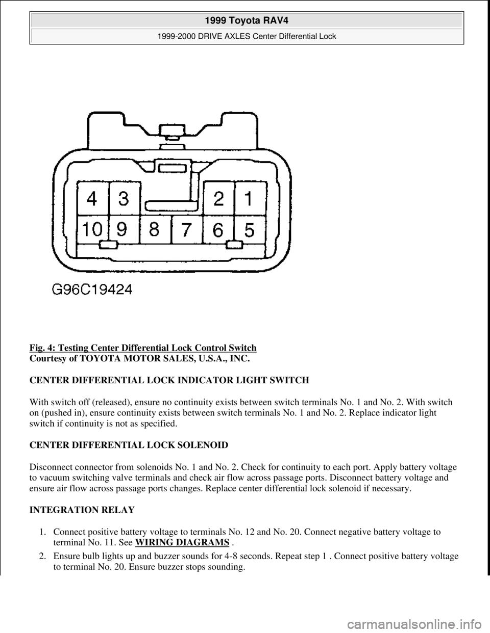
Fig. 4: Testing Center Differential Lock Control Switch
Courtesy of TOYOTA MOTOR SALES, U.S.A., INC.
CENTER DIFFERENTIAL LOCK INDICATOR LIGHT SWITCH
With switch off (released), ensure no continuity exists between switch terminals No. 1 and No. 2. With switch
on (pushed in), ensure continuity exists between switch terminals No. 1 and No. 2. Replace indicator light
switch if continuity is not as specified.
CENTER DIFFERENTIAL LOCK SOLENOID
Disconnect connector from solenoids No. 1 and No. 2. Check for continuity to each port. Apply battery voltage
to vacuum switching valve terminals and check air flow across passage ports. Disconnect battery voltage and
ensure air flow across passage ports changes. Replace center differential lock solenoid if necessary.
INTEGRATION RELAY
1. Connect positive battery voltage to terminals No. 12 and No. 20. Connect negative battery voltage to
terminal No. 11. See WIRING DIAGRAMS
.
2. Ensure bulb lights up and buzzer sounds for 4-8 seconds. Repeat step 1 . Connect positive battery voltage
to terminal No. 20. Ensure buzzer stops sounding.
1999 Toyota RAV4
1999-2000 DRIVE AXLES Center Differential Lock
Microsoft
Sunday, November 22, 2009 10:08:59 AMPage 6 © 2005 Mitchell Repair Information Company, LLC.
Page 407 of 1632
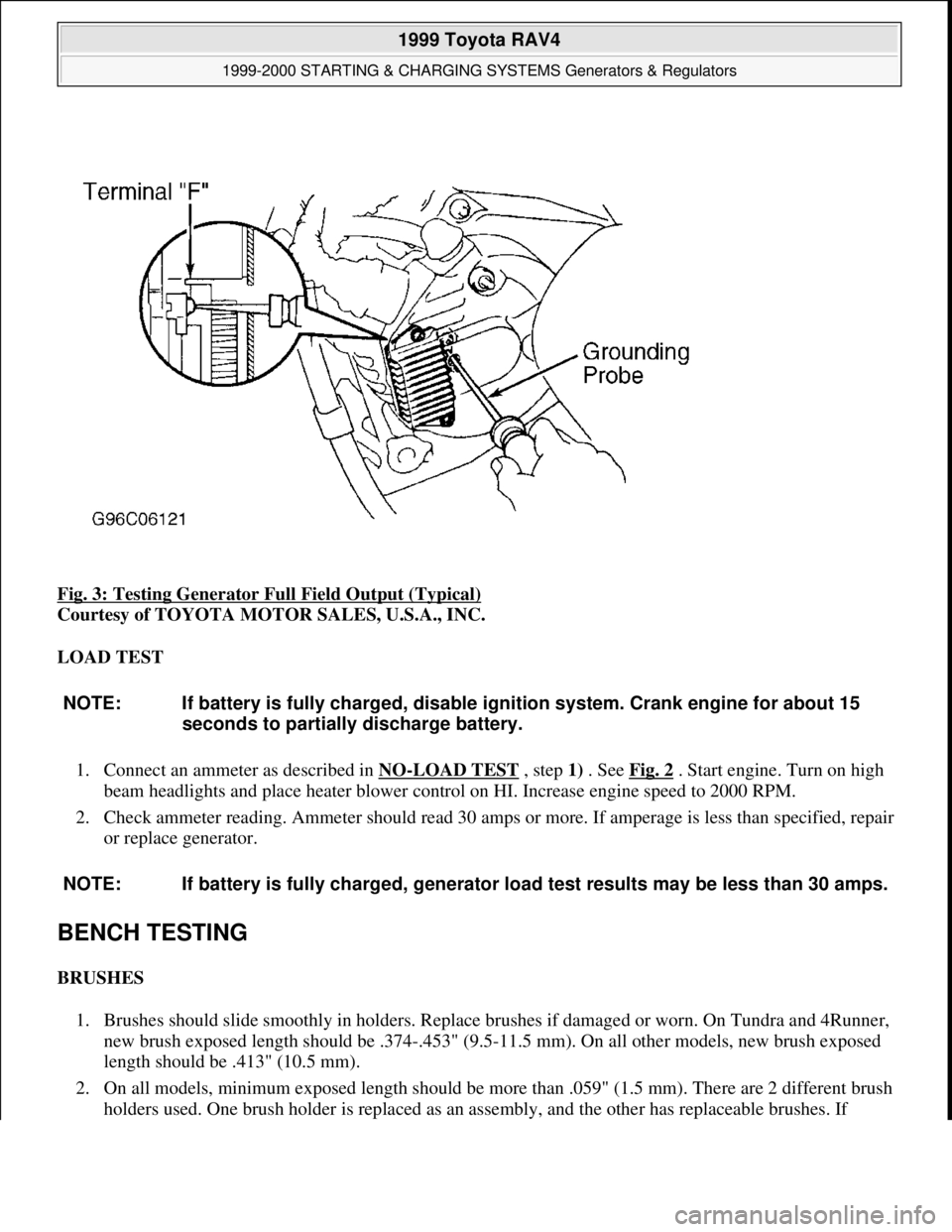
Fig. 3: Testing Generator Full Field Output (Typical)
Courtesy of TOYOTA MOTOR SALES, U.S.A., INC.
LOAD TEST
1. Connect an ammeter as described in NO
-LOAD TEST , step 1) . See Fig. 2 . Start engine. Turn on high
beam headlights and place heater blower control on HI. Increase engine speed to 2000 RPM.
2. Check ammeter reading. Ammeter should read 30 amps or more. If amperage is less than specified, repair
or replace generator.
BENCH TESTING
BRUSHES
1. Brushes should slide smoothly in holders. Replace brushes if damaged or worn. On Tundra and 4Runner,
new brush exposed length should be .374-.453" (9.5-11.5 mm). On all other models, new brush exposed
length should be .413" (10.5 mm).
2. On all models, minimum exposed length should be more than .059" (1.5 mm). There are 2 different brush
holders used. One brush holder is replaced as an assembl
y, and the other has replaceable brushes. If
NOTE: If battery is fully charged, disable ignition system. Crank engine for about 15
seconds to partially discharge battery.
NOTE: If battery is fully charged, generator load test results may be less than 30 amps.
1999 Toyota RAV4
1999-2000 STARTING & CHARGING SYSTEMS Generators & Regulators
Microsoft
Sunday, November 22, 2009 10:13:07 AMPage 6 © 2005 Mitchell Repair Information Company, LLC.
Page 535 of 1632
1. Check stoplight operation. If stoplight operation is okay, go to next step. If stoplights DO NOT operate
correctly, check and repair stoplight system as necessary. See WIRING DIAGRAMS
.
2. Perform CANCEL SWITCHES test under CRUISE CONTROL FUNCTION TEST
under TROUBLE
SHOOTING. If stoplight input signal is not as specified, go to next step. If stoplight input signal is as
specified, no problem is indicated at this time. Fault may be intermittent. If sent here from SYMPTOM
DIAGNOSIS, perform next test listed.
3. Remove cruise control ECU with connector attached. See Fig. 1
. Turn ignition switch to ON position.
Backprobing cruise control ECU connector, measure voltage between ground and cruise control ECU
connector terminal No. 2 (Green/White wire). With brake pedal depressed, battery voltage should exist.
With brake pedal released, voltage should be less than one volt. If voltage is not as specified, go to next
step. If voltage is as specified, no problem is indicated at this time. Fault may be intermittent. If sent here
from SYMPTOM DIAGNOSIS, perform next test listed.
4. Check for open circuit in wiring harness and connectors between cruise control ECU and stoplight switch.
Repair as necessary and retest system. If wiring harness and connectors are okay, replace cruise control
ECU and retest system.
IDLE SIGNAL CIRCUIT
1. Remove cruise control ECU with connector attached. Disconnect Engine Control Module (ECM) 16-pin
connector. ECM is located behind bottom center of instrument panel, in front of console. Turn ignition
switch to ON position. Backprobing connector, measure voltage between ground and cruise control ECU
connector terminal No. 13 (Blue wire).
2. With throttle valve fully open, battery voltage should exist. With throttle valve fully closed, voltage
should be less than 2 volts. If voltage is not as specified, go to next step. If voltage is as specified, no
problem is indicated at this time. Fault may be intermittent. If sent here from SYMPTOM DIAGNOSIS,
perform next test listed.
3. Check wiring harness and connectors between ECM and TP sensor. Repair as necessary and retest
system. If wiring harness and connectors are okay, go to next step.
4. Disconnect TP sensor 3-pin Black connector. Measure resistance between TP sensor connector terminals
No. 2 (Brown wire) and No. 3 (Blue/Red wire). Resistance should be 2000-10,200 ohms with throttle
valve fully opened, and 200-6300 ohms with throttle valve fully closed. If resistance is as specified, go to
next step. If resistance is not as specified, replace TP sensor and retest system.
5. Check wiring harness and connectors between cruise control ECU and TP sensor, and between TP sensor
and ground. Repair as necessary and retest system. If wiring harness and connectors are okay, replace
cruise control ECU and retest system.
ELECTRONICALLY CONTROLLED TRANSMISSION (ECT) CIRCUIT
1. Start engine and bring to operating temperature. Drive vehicle and ensure overdrive operation is turned on
and off when overdrive ON-OFF switch is operated. If overdrive switch is okay, go to next step. If
overdrive switch is not okay, see appropriate ELECTRONIC CONTROLS article in AUTOMATIC NOTE: Ensure Throttle Position (TP) sensor circuit is operating as designed, and no
fault codes are present for TP sensor circuit. See appropriate ON-VEHICLE
ADJUSTMENTS article in ENGINE PERFORMANCE.
1999 Toyota RAV4
1999 ACCESSORIES & EQUIPMENT Cruise Control Systems - RAV4
Microsoft
Sunday, November 22, 2009 10:52:01 AMPage 11 © 2005 Mitchell Repair Information Company, LLC.
Page 891 of 1632
1999-2000 ACCESSORIES & EQUIPMENT
Instrument Panels - Trucks
DESCRIPTION & OPERATION
GAUGES
Standard instrument clusters contain fuel and temperature gauges with telltale warning lights. Some optional
instrument panels are equipped with a tachometer, oil pressure gauge and voltmeter. Gauge internal operating
components use either a 2-terminal bimetallic strip type or a 3-terminal coil type. The 2-terminal type gauges
are generally used on clusters without tachometers.
SWITCHES
All models contain hazard warning switch on instrument panel. All models use a combination switch for
headlight, turn signal, wiper/washer, and cruise control switches. Combination switch is mounted on steering
column. For testing and/or removal and installation procedures for combination switch components, see
appropriate STEERING COLUMN SWITCHES article.
COMPONENT TESTS
A/T OIL TEMPERATURE SWITCH
RAV4
1. Turn ignition switch to OFF position. Disconnect A/T oil temperature switch 1-pin connector. Switch is
located on side of transaxle, near park/neutral position switch. Remove A/T oil temperature switch. Place
probe end of switch and thermometer in a container of water.
2. Connect an ohmmeter between switch terminal and switch body. Heat water and check for continuity.
With temperature at 284-302°F (140-150°C), continuity should exist. If continuity does not exist, replace
switch.
A/T OIL TEMPERATURE WARNING LIGHT
RAV4
Disconnect A/T oil temperature switch connector. Switch is located on side of transaxle, near park/neutral
position switch. Using a jumper wire, connect switch connector terminal to ground. Turn ignition switch to ON
position. A/T oil temperature warning light should be on. If warning light is off, check bulb and wiring harness.
Repair as necessary. WARNING:Deactivate air bag system before performing any service operation. See
AIR BAG RESTRAINT SYSTEMS article. DO NOT apply electrical power to
any component on steering column without first deactivating air bag
system. Air bag may deploy.
1999 Toyota RAV4
1999-2000 ACCESSORIES & EQUIPMENT Instrument Panels - Trucks
1999 Toyota RAV4
1999-2000 ACCESSORIES & EQUIPMENT Instrument Panels - Trucks
Microsoft
Sunday, November 22, 2009 10:54:09 AMPage 1 © 2005 Mitchell Repair Information Company, LLC.
Microsoft
Sunday, November 22, 2009 10:54:14 AMPage 1 © 2005 Mitchell Repair Information Company, LLC.
Page 950 of 1632
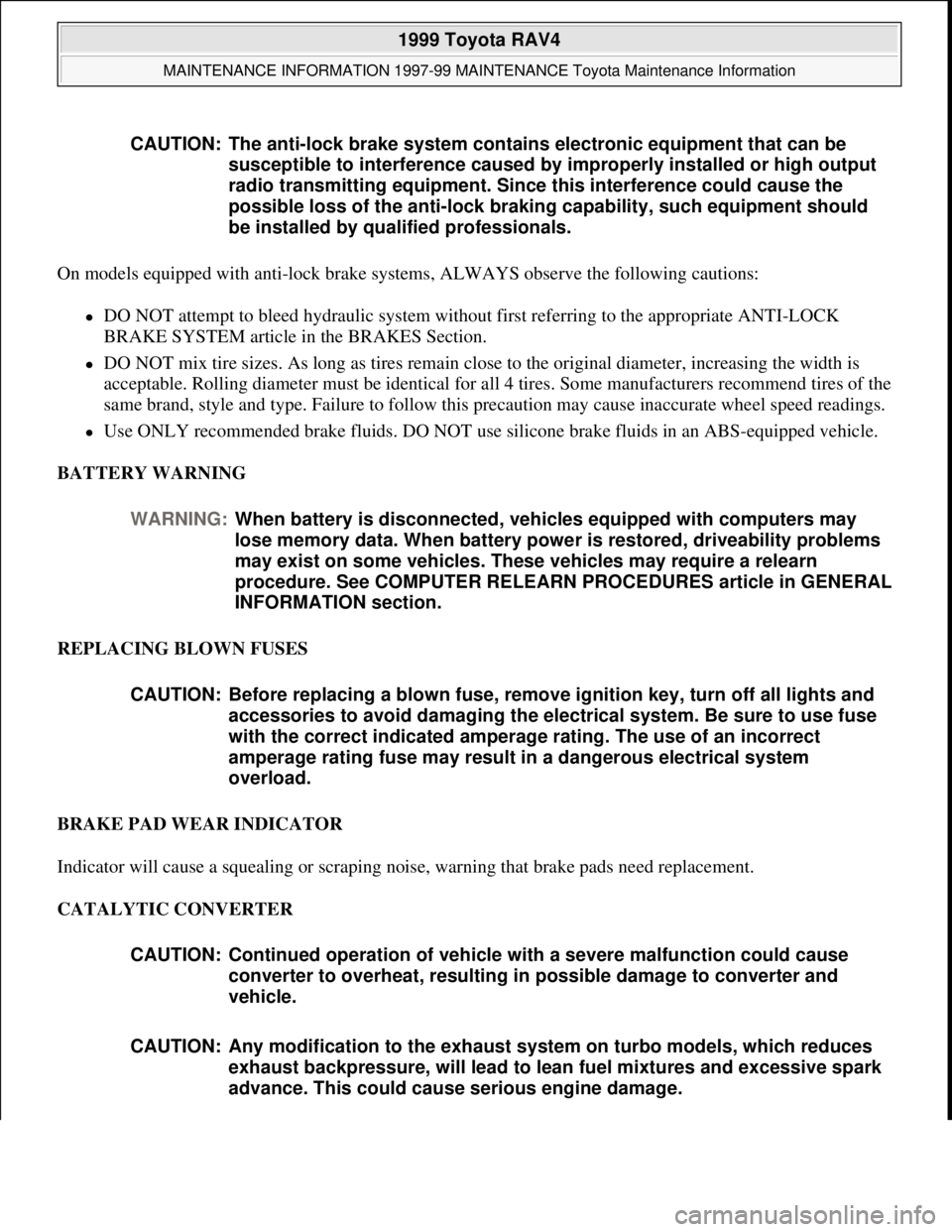
On models equipped with anti-lock brake systems, ALWAYS observe the following cautions:
DO NOT attempt to bleed hydraulic system without first referring to the appropriate ANTI-LOCK
BRAKE SYSTEM article in the BRAKES Section.
DO NOT mix tire sizes. As long as tires remain close to the original diameter, increasing the width is
acceptable. Rolling diameter must be identical for all 4 tires. Some manufacturers recommend tires of the
same brand, style and type. Failure to follow this precaution may cause inaccurate wheel speed readings.
Use ONLY recommended brake fluids. DO NOT use silicone brake fluids in an ABS-equipped vehicle.
BATTERY WARNING
REPLACING BLOWN FUSES
BRAKE PAD WEAR INDICATOR
Indicator will cause a squealing or scraping noise, warning that brake pads need replacement.
CATALYTIC CONVERTER CAUTION: The anti-lock brake system contains electronic equipment that can be
susceptible to interference caused by improperly installed or high output
radio transmitting equipment. Since this interference could cause the
possible loss of the anti-lock braking capability, such equipment should
be installed by qualified professionals.
WARNING:When battery is disconnected, vehicles equipped with computers may
lose memory data. When battery power is restored, driveability problems
may exist on some vehicles. These vehicles may require a relearn
procedure. See COMPUTER RELEARN PROCEDURES article in GENERAL
INFORMATION section.
CAUTION: Before replacing a blown fuse, remove ignition key, turn off all lights and
accessories to avoid damaging the electrical system. Be sure to use fuse
with the correct indicated amperage rating. The use of an incorrect
amperage rating fuse may result in a dangerous electrical system
overload.
CAUTION: Continued operation of vehicle with a severe malfunction could cause
converter to overheat, resulting in possible damage to converter and
vehicle.
CAUTION: Any modification to the exhaust system on turbo models, which reduces
exhaust backpressure, will lead to lean fuel mixtures and excessive spark
advance. This could cause serious engine damage.
1999 Toyota RAV4
MAINTENANCE INFORMATION 1997-99 MAINTENANCE Toyota Maintenance Information
Microsoft
Sunday, November 22, 2009 10:32:42 AMPage 8 © 2005 Mitchell Repair Information Company, LLC.
Page 968 of 1632
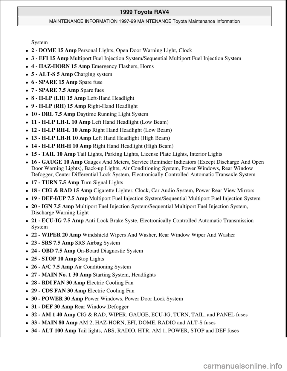
System
2 - DOME 15 Amp Personal Lights, Open Door Warning Light, Clock
3 - EFI 15 Amp Multiport Fuel Injection System/Sequential Multiport Fuel Injection System
4 - HAZ-HORN 15 Amp Emergency Flashers, Horns
5 - ALT-S 5 Amp Charging system
6 - SPARE 15 Amp Spare fuse
7 - SPARE 7.5 Amp Spare fues
8 - H-LP (LH) 15 Amp Left-Hand Headlight
9 - H-LP (RH) 15 Amp Right-Hand Headlight
10 - DRL 7.5 Amp Daytime Running Light System
11 - H-LP LH-L 10 Amp Left Hand Headlight (Low Beam)
12 - H-LP RH-L 10 Amp Right Hand Headlight (Low Beam)
13 - H-LP LH-H 10 Amp Left Hand Headlight (High Beam)
14 - H-LP RH-H 10 Amp Right Hand Headlight (High Beam)
15 - TAIL 10 Amp Tail Lights, Parking Lights, License Plate Lights, Interior Lights
16 - GAUGE 10 Amp Gauges And Meters, Service Reminder Indicators (Except Discharge And Open
Door Warning Lights), Back-up Lights, Air Conditioning System, Power Windows, Rear Window
Defogger, Center Differential Lock System, Electronically Controlled Automatic Transaxle System
17 - TURN 7.5 Amp Turn Signal Lights
18 - CIG & RAD 15 Amp Cigarette Lighter, Clock, Car Audio System, Power Rear View Mirrors
19 - DEF-I/UP 7.5 Amp Multiport Fuel Injection System/Sequential Multiport Fuel Injection System
20 - IGN 7.5 Amp Multiport Fuel Injection System/Sequential Multiport Fuel Injection System,
Discharge Warning Light
21 - ECU-IG 7.5 Amp Anti-Lock Brake Syste, Electronically Controlled Automatic Transmission
System
22 - WIPER 20 Amp Windshield Wipers And Washer, Rear Window Wiper And Washer
23 - SRS 7.5 Amp SRS Airbag System
24 - OBD 7.5 Amp On-Board Diagnostic System
25 - STOP 10 Amp Stop Lights
26 - A/C 7.5 Amp Air Conditioning System
27 - MAIN No. 1 30 Amp Starting System, Headlights
28 - RDI FAN 30 Amp Electric Cooling Fan
29 - CDS FAN 30 Amp Electric Cooling Fan
30 - POWER 30 Amp Power Windows, Power Door Lock System
31 - DEF 30 Amp Rear Window Defogger
32 - AM 1 40 Amp CIG & RAD, WIPER, GAUGE, ECU-IG, TURN, TAIL, and PANEL fuses
33 - MAIN 80 Amp AM 2, HAZ-HORN, EFI, DOME, RADIO and ALT-S fuses
34 - ALT 100 Amp Tail lights, ABS, RADIO, HTR, AM 1, POWER, STOP and DEF fuses
1999 Toyota RAV4
MAINTENANCE INFORMATION 1997-99 MAINTENANCE Toyota Maintenance Information
Microsoft
Sunday, November 22, 2009 10:32:42 AMPage 26 © 2005 Mitchell Repair Information Company, LLC.