service indicator TOYOTA RAV4 1996 Service Repair Manual
[x] Cancel search | Manufacturer: TOYOTA, Model Year: 1996, Model line: RAV4, Model: TOYOTA RAV4 1996Pages: 1632, PDF Size: 41.64 MB
Page 174 of 1632
TORQUE CONVERTER
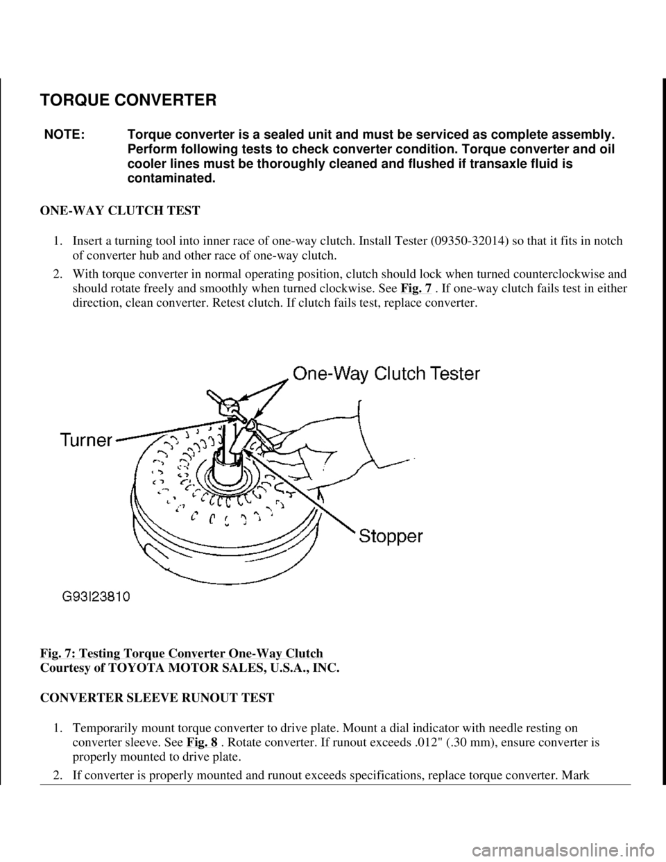
ONE-WAY CLUTCH TEST
1. Insert a turning tool into inner race of one-way clutch. Install Tester (09350-32014) so that it fits in notch
of converter hub and other race of one-way clutch.
2. With torque converter in normal operating position, clutch should lock when turned counterclockwise and
should rotate freely and smoothly when turned clockwise. See Fig. 7
. If one-way clutch fails test in either
direction, clean converter. Retest clutch. If clutch fails test, replace converter.
Fig. 7: Testing Torque Converter One
-Way Clutch
Courtesy of TOYOTA MOTOR SALES, U.S.A., INC.
CONVERTER SLEEVE RUNOUT TEST
1. Temporarily mount torque converter to drive plate. Mount a dial indicator with needle resting on
converter sleeve. See Fig. 8
. Rotate converter. If runout exceeds .012" (.30 mm), ensure converter is
properly mounted to drive plate.
2. If converter is properl
y mounted and runout exceeds specifications, replace torque converter. Mark NOTE: Torque converter is a sealed unit and must be serviced as complete assembly.
Perform following tests to check converter condition. Torque converter and oil
cooler lines must be thoroughly cleaned and flushed if transaxle fluid is
contaminated.
1998 Toyota Avalon XLS
1997-99 AUTOMATIC TRANSMISSIONS Toyota A-540E, A-540H & A-541E Overhaul
Helpmelearn
November-03-08 10:28:17 AMPage 20 © 2005 Mitchell Repair Information Company, LLC.
Page 538 of 1632
DIAGNOSIS, perform next test listed.
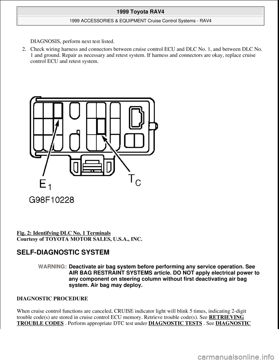
2. Check wiring harness and connectors between cruise control ECU and DLC No. 1, and between DLC No.
1 and ground. Repair as necessary and retest system. If harness and connectors are okay, replace cruise
control ECU and retest system.
Fig. 2: Identifying DLC No. 1 Terminals
Courtesy of TOYOTA MOTOR SALES, U.S.A., INC.
SELF-DIAGNOSTIC SYSTEM
DIAGNOSTIC PROCEDURE
When cruise control functions are canceled, CRUISE indicator light will blink 5 times, indicating 2-digit
trouble code(s) are stored in cruise control ECU memory. Retrieve trouble code(s). See RETRIEVING
TROUBLE CODES . Perform appropriate DTC test under DIAGNOSTIC TESTS . See DIAGNOSTIC
WARNING:Deactivate air bag system before performing any service operation. See
AIR BAG RESTRAINT SYSTEMS article. DO NOT apply electrical power to
any component on steering column without first deactivating air bag
system. Air bag may deploy.
1999 Toyota RAV4
1999 ACCESSORIES & EQUIPMENT Cruise Control Systems - RAV4
Microsoft
Sunday, November 22, 2009 10:52:01 AMPage 14 © 2005 Mitchell Repair Information Company, LLC.
Page 539 of 1632
TROUBLE CODE DEFINITIONS table.
If a fault or symptom is present, but no trouble codes were set, perform CRUISE CONTROL FUNCTION
TEST under TROUBLE SHOOTING. Cruise control function test will cause CRUISE indicator light to display
a one-digit function code if circuit tested is okay. After performing cruise control function test, if system still
does not operate properly and no self-diagnostic trouble codes are present, perform SYMPTOM DIAGNOSIS
under TROUBLE SHOOTING.
READING TROUBLE CODES
Trouble codes are displayed as flashes of CRUISE indicator light. All trouble codes are 2-digit numbers. Cruise
control ECU outputs trouble codes from lowest to highest. These codes indicate current faults in system and
should be serviced in order of appearance. Pay careful attention to length of pauses in order to read codes
correctly. See Fig. 3
.
1999 Toyota RAV4
1999 ACCESSORIES & EQUIPMENT Cruise Control Systems - RAV4
Microsoft
Sunday, November 22, 2009 10:52:01 AMPage 15 © 2005 Mitchell Repair Information Company, LLC.
Page 719 of 1632
3. Check camshaft end play with camshaft bearing cap bolts tightened to specification. Replace camshaft
and/or cylinder head if camshaft end play is not within specification. See CAMSHAFT
table under
ENGINE SPECIFICATIONS.
4. Install both camshafts in cylinder head without sub-gear installed on exhaust camshaft. Install and tighten
camshaft bearing cap bolts to specification in sequence. See Fig. 22
and Fig. 23 . See TORQUE
SPECIFICATIONS .
5. Using dial indicator, check gear backlash between gears on camshafts. Replace camshafts if gear backlash
exceeds specification. See CAMSHAFT
table under ENGINE SPECIFICATIONS.
6. Measure length of camshaft gear spring. Replace camshaft gear spring if distance is not within
specification. See CAMSHAFT
table under ENGINE SPECIFICATIONS. Measure valve lifter diameter
and bore diameter. Ensure oil clearance is within specification. Replace components if not within
specification. See VALVE LIFTERS
table under ENGINE SPECIFICATIONS.
Installation
1. If installing sub-gear on exhaust camshaft, install camshaft gear spring, sub-gear, wave washer and snap
ring on exhaust camshaft. Ensure pins on main gear and sub-gear engage with ends of camshaft gear
spring.
2. Install service bolt "A" on sub-gear. See Fig. 24
. Using screwdriver, rotate sub-gear clockwise and align
hole in sub-gear with hole on main gear. Install service bolt "B". Remove service bolt "A".
3. Install adjusting shims and valve lifters in original location on cylinder head (if removed). Ensure valve
lifters rotate smoothly in cylinder head.
4. Coat thrust surfaces of camshafts with multipurpose grease. To install intake camshaft, rotate intake
camshaft so knock pin is at 80-115 degrees from vertical position, and install into cylinder head. See Fig.
19 .
5. Coat seal lip of NEW oil seal for intake camshaft with grease. Install oil seal onto front of intake camshaft
until oil seal is fully seated in cylinder head. Apply sealant to front camshaft bearing cap for intake
camshaft. See Fig. 25
.
1999 Toyota RAV4
1999-2000 ENGINES 2.0L 4-Cylinder
Microsoft
Sunday, November 22, 2009 10:22:26 AMPage 36 © 2005 Mitchell Repair Information Company, LLC.
Page 784 of 1632
and/or cylinder head if camshaft end play is not within specification. See CAMSHAFT under ENGINE
SPECIFICATIONS.
4. Install both camshafts in cylinder head without sub-gear installed on exhaust camshaft. Install and tighten
camshaft bearing cap bolts to specification in sequence. See Fig. 23
and Fig. 24 . See TORQUE
SPECIFICATIONS .
5. Using dial indicator, check gear backlash between gears on camshafts. Replace camshafts if gear backlash
exceeds specification. See CAMSHAFT
under ENGINE SPECIFICATIONS.
6. Measure distance between ends of camshaft gear spring. Replace camshaft gear spring if distance is
not .886-.902" (22.50-22.90 mm). Measure valve lifter diameter and bore diameter. Ensure oil clearance
is within specification. Replace components if not within specification. See VALVE LIFTERS
under
ENGINE SPECIFICATIONS.
Installation
1. If installing sub-gear on exhaust camshaft, install camshaft gear spring, sub-gear, wave washer and snap
ring on exhaust camshaft. Ensure pins on main gear and sub-gear engage with ends of camshaft gear
spring.
2. Install service bolt "A" on sub-gear. See Fig. 25
. Using screwdriver, rotate sub-gear clockwise and align
holes in sub-gear with hole on main gear. Install service bolt "B". Remove service bolt "A".
3. Install adjusting shims and valve lifters in original location on cylinder head (if removed). Ensure valve
lifters rotate smoothly in cylinder head.
4. Coat thrust surfaces of camshafts with multipurpose grease. To install intake camshaft, rotate intake
camshaft so knock pin is at 80-115 degrees from vertical position and install in cylinder head. See Fig.
20 .
5. Coat seal lip of NEW oil seal for intake camshaft with grease. Install oil seal on front of intake camshaft
until oil seal is fully seated in cylinder head. Apply sealant on front camshaft bearing cap for intake
camshaft. See Fig. 26
.
1997 Toyota RAV4
2.0L 4-CYL 1997-98 ENGINES Toyota 2.0L 4-Cylinder
Microsoft
Sunday, November 22, 2009 10:23:31 AMPage 36 © 2005 Mitchell Repair Information Company, LLC.
Page 876 of 1632
TROUBLE SHOOTING
A/C INDICATOR BLINKS
Check for faulty compressor, A/C switch or A/C amplifier. Check for faulty wiring harness, grounds or
connectors.
BLOWER MOTOR DOES NOT OPERATE
Check for blown HTR fuse, heater main relay or blower resistor. Check for faulty A/C controls, blower switch
or blower motor. Check for faulty wiring harness, grounds or connectors.
COMPRESSOR DOES NOT OPERATE
Check for incorrect refrigerant charge. Check for blown A/C fuse. Check for faulty heater main relay,
compressor clutch, compressor, dual-pressure switch, A/C switch, blower switch, A/C amplifier, thermistor,
wiring harnesses, grounds or connectors.
COMPRESSOR OPERATES INTERMITTENTLY
Check for incorrect refrigerant charge. Check for faulty dual-pressure switch. Check for bent or dented
refrigerant lines. Check for faulty A/C amplifier, thermistor, wiring harness, grounds or connectors.
INSUFFICIENT COOLING
Check for incorrect refrigerant charge or incorrect system pressures. Check for slipping A/C drive belt. Check
for clogged condenser. Check for plugged receiver-drier. Check for bent or dented refrigerant lines. Check for
faulty compressor clutch, A/C compressor, A/C amplifier, thermistor, evaporator or expansion valve.
NO ENGINE IDLE UP WHEN A/C SWITCH IS ON
Check for faulty A/C amplifier, IAC system, wiring and/or wiring connections.
TESTING
NOTE: For control cable adjustments, see HEATER SYSTEMS - RAV4, TACOMA &
4RUNNER article.
WARNING:To avoid injury from accidental air bag deployment, read and carefully
follow all SERVICE PRECAUTIONS and DISABLING & ACTIVATING AIR
BAG SYSTEM procedures in AIR BAG SYSTEM SAFETY article in
GENERAL SERVICING.
NOTE: For testing procedures not covered in this article, see HEATER SYSTEMS -
RAV4, TACOMA & 4RUNNER article.
1999 Toyota RAV4
1999 MANUAL A/C-HEATER SYSTEMS RAV4
Microsoft
Sunday, November 22, 2009 10:29:28 AMPage 3 © 2005 Mitchell Repair Information Company, LLC.
Page 968 of 1632
System
2 - DOME 15 Amp Personal Lights, Open Door Warning Light, Clock
3 - EFI 15 Amp Multiport Fuel Injection System/Sequential Multiport Fuel Injection System
4 - HAZ-HORN 15 Amp Emergency Flashers, Horns
5 - ALT-S 5 Amp Charging system
6 - SPARE 15 Amp Spare fuse
7 - SPARE 7.5 Amp Spare fues
8 - H-LP (LH) 15 Amp Left-Hand Headlight
9 - H-LP (RH) 15 Amp Right-Hand Headlight
10 - DRL 7.5 Amp Daytime Running Light System
11 - H-LP LH-L 10 Amp Left Hand Headlight (Low Beam)
12 - H-LP RH-L 10 Amp Right Hand Headlight (Low Beam)
13 - H-LP LH-H 10 Amp Left Hand Headlight (High Beam)
14 - H-LP RH-H 10 Amp Right Hand Headlight (High Beam)
15 - TAIL 10 Amp Tail Lights, Parking Lights, License Plate Lights, Interior Lights
16 - GAUGE 10 Amp Gauges And Meters, Service Reminder Indicators (Except Discharge And Open
Door Warning Lights), Back-up Lights, Air Conditioning System, Power Windows, Rear Window
Defogger, Center Differential Lock System, Electronically Controlled Automatic Transaxle System
17 - TURN 7.5 Amp Turn Signal Lights
18 - CIG & RAD 15 Amp Cigarette Lighter, Clock, Car Audio System, Power Rear View Mirrors
19 - DEF-I/UP 7.5 Amp Multiport Fuel Injection System/Sequential Multiport Fuel Injection System
20 - IGN 7.5 Amp Multiport Fuel Injection System/Sequential Multiport Fuel Injection System,
Discharge Warning Light
21 - ECU-IG 7.5 Amp Anti-Lock Brake Syste, Electronically Controlled Automatic Transmission
System
22 - WIPER 20 Amp Windshield Wipers And Washer, Rear Window Wiper And Washer
23 - SRS 7.5 Amp SRS Airbag System
24 - OBD 7.5 Amp On-Board Diagnostic System
25 - STOP 10 Amp Stop Lights
26 - A/C 7.5 Amp Air Conditioning System
27 - MAIN No. 1 30 Amp Starting System, Headlights
28 - RDI FAN 30 Amp Electric Cooling Fan
29 - CDS FAN 30 Amp Electric Cooling Fan
30 - POWER 30 Amp Power Windows, Power Door Lock System
31 - DEF 30 Amp Rear Window Defogger
32 - AM 1 40 Amp CIG & RAD, WIPER, GAUGE, ECU-IG, TURN, TAIL, and PANEL fuses
33 - MAIN 80 Amp AM 2, HAZ-HORN, EFI, DOME, RADIO and ALT-S fuses
34 - ALT 100 Amp Tail lights, ABS, RADIO, HTR, AM 1, POWER, STOP and DEF fuses
1999 Toyota RAV4
MAINTENANCE INFORMATION 1997-99 MAINTENANCE Toyota Maintenance Information
Microsoft
Sunday, November 22, 2009 10:32:42 AMPage 26 © 2005 Mitchell Repair Information Company, LLC.
Page 969 of 1632
35 - HTR 50 Amp Air Conditioning system
36 - ABS 60 Amp Anti-Lock brake system
Fuse & Circuit Breaker Identificatio - 1998
1 - H-LP (LH) 15 Amp Left-Hand Headlight
2 - H-LP (RH) 15 Amp Right-Hand Headlight
3 - SPARE 10 Amp Spare fuse
4 - SPARE 15 Amp Spare fuse
5 - AM2 5 Amp Multiport Fuel Injection System/Sequential Multiport Fuel Injection System, SRS
Airbag System, Seat Belt Pretensioners, Starting System, Discharge Warning Light
6 - ALT-S 5 Amp Charging system
7 - HAZ 10 Amp Emergency Flashers
8 - EFI 20 Amp (USA) or 15 Amp (Canada)Multiport Fuel Injection System/Sequential Multiport Fuel
Injection System
9 - DOME 15 Amp Personal Lights, Open Door Warning Light, Clock
10 - IGN 20 Amp Charging System
11 - H-LP LH-H 10 Amp Left Hand Headlight (High Beam)
12 - H-LP RH-H 10 Amp Right Hand Headlight (High Beam)
13 - H-LP LH-L 10 Amp Left Hand Headlight (Low Beam)
14 - H-LP RH-L 10 Amp Right Hand Headlight (Low Beam)
15 - SEAT-HTR 10 Amp No Circuit
16 - PWR OUTLET 15 Amp Power Outlet
17 - CIG 15 Amp Cigarette Lighter, Clock, Car Audio System, Power Rear View Mirrors, Electronically
Controlled Automatic Transmission
18 - SRS-SCC 10 Amp SRS Airbag System, Seat Belt Pretensioners
19 - WIPER 20 Amp Windshield Wipers And Washer, Rear Window Wiper And Washer
20 - ECU-IG 10 Amp Electronically Controlled Automatic Transmission System, Rear Window
Defogger, Center Differential Lock System, Electric Moon Roof, Multiport Fuel Injection System,
Electric Cooling Fan, Anti-Lock Brake System, Cruise Control System
21 - TURN & GAUGE 10 Amp Turn Signal Lights, Gauges & Meters, Back-Up Lights, Service
Reminder Indicators, Air Conditioning System, Daytime Running Light System
22 - STOP 10 Amp Stop Lights, High Mounted Stop Light, Electronically Controlled Automatic
Transmission System, Anti-Lock Brake System
23 - TAIL 15 Amp Gauges & Meters, Emergency Flashers, Cigarette Lighter, Center Differential Lock
System, Clock, Rear Window Defogger, Air Conditioning System, Electronically Controlled Automatic
Transmission System, Car Audio System, Tail Lights, License Plate Lights, Parking Lights, Instrument
Panel Light Control, Side Marker Lights
24 - OBD 10 Amp On-Board Diagnosis System
25 - SRS-B 10 Amp SRS Air Bag Warning Light
1999 Toyota RAV4
MAINTENANCE INFORMATION 1997-99 MAINTENANCE Toyota Maintenance Information
Microsoft
Sunday, November 22, 2009 10:32:42 AMPage 27 © 2005 Mitchell Repair Information Company, LLC.
Page 972 of 1632
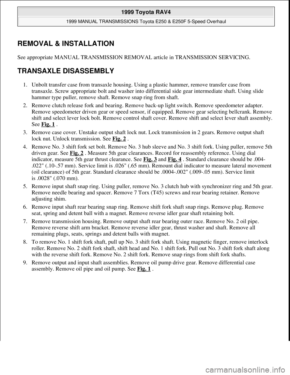
REMOVAL & INSTALLATION
See appropriate MANUAL TRANSMISSION REMOVAL article in TRANSMISSION SERVICING.
TRANSAXLE DISASSEMBLY
1. Unbolt transfer case from transaxle housing. Using a plastic hammer, remove transfer case from
transaxle. Screw appropriate bolt and washer into differential side gear intermediate shaft. Using slide
hammer type puller, remove shaft. Remove snap ring from shaft.
2. Remove clutch release fork and bearing. Remove back-up light switch. Remove speedometer adapter.
Remove speedometer driven gear or speed sensor, if equipped. Remove gear selecting bellcrank. Remove
shift and select lever lock bolt. Remove control shaft cover. Remove shift and select lever shaft assembly.
See Fig. 1
.
3. Remove case cover. Unstake output shaft lock nut. Lock transmission in 2 gears. Remove output shaft
lock nut. Unlock transmission. See Fig. 2
.
4. Remove No. 3 shift fork set bolt. Remove No. 3 hub sleeve and No. 3 shift fork. Using puller, remove 5th
driven gear. See Fig. 2
. Measure 5th gear clearances. Record for reassembly reference. Using dial
indicator, measure 5th gear thrust clearance. See Fig. 3
and Fig. 4 . Standard clearance should be .004-
.022" (.10-.57 mm). Service limit is .026" (.65 mm). Remount dial indicator to measure lateral movement
(oil clearance) of 5th gear. Standard clearance should be .0004-.002" (.009-.05 mm). Service limit
is .0028" (.070 mm).
5. Remove input shaft snap ring. Using puller, remove No. 3 clutch hub with synchronizer ring and 5th gear.
Remove needle bearing and spacer. Remove 7 Torx (T45) screws and rear bearing retainer. Remove
adjusting shim.
6. Remove input shaft rear bearing snap ring. Remove shift fork shaft snap rings. Remove plug. Remove
seat, spring and detent ball with a magnet. Remove reverse idler gear shaft retaining bolt.
7. Remove transmission housing. Remove output shaft rear bearing outer race. Remove No. 2 oil pipe.
Remove reverse shift arm bracket. Remove reverse idler gear, thrust washer and shaft. Remove all
remaining plugs, seats, springs and detent balls with magnet.
8. To remove No. 1 shift fork shaft, pull up No. 3 shift fork shaft. Using magnetic finger, remove interlock
roller. Remove No. 2 shift fork shaft, shift head and No. 1 shift fork. Pull out No. 3 shift fork shaft along
with the reverse shift fork. Remove No. 2 shift fork. Remove snap rings from shift fork shafts.
9. Remove output and input shaft assemblies. Remove oil pump drive gear. Remove differential case
assembly. Remove oil pipe and oil pump. See Fig. 1
.
1999 Toyota RAV4
1999 MANUAL TRANSMISSIONS Toyota E250 & E250F 5-Speed Overhaul
Microsoft
Sunday, November 22, 2009 10:48:07 AMPage 2 © 2005 Mitchell Repair Information Company, LLC.
Page 977 of 1632
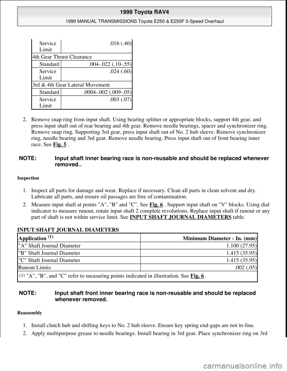
2. Remove snap ring from input shaft. Using bearing splitter or appropriate blocks, support 4th gear, and
press input shaft out of rear bearing and 4th gear. Remove needle bearings, spacer and synchronizer ring.
Remove snap ring. Supporting 3rd gear, press input shaft out of No. 2 hub sleeve. Remove synchronizer
ring, needle bearing and 3rd gear. Remove needle bearing. Press input shaft out of front bearing inner
race. See Fig. 5
.
Inspection
1. Inspect all parts for damage and wear. Replace if necessary. Clean all parts in clean solvent and dry.
Lubricate all parts, and ensure oil passages are free of contamination.
2. Measure input shaft at points "A", "B" and "C". See Fig. 6
. Support input shaft on "V" blocks. Using dial
indicator to measure runout, rotate input shaft 2 complete revolutions. Replace input shaft if runout or any
part of shaft is not within service limit. See INPUT SHAFT JOURNAL DIAMETERS
table.
INPUT SHAFT JOURNAL DIAMETERS
Reassembly
1. Install clutch hub and shifting keys to No. 2 hub sleeve. Ensure key spring end-gaps are not in-line.
2. Apply multipurpose grease to needle bearings. Install bearing in 3rd gear. Place synchronizer ring on 3rd
Service
Limit.016 (.40)
4th Gear Thrust Clearance
Standard.004-.022 (.10-.55)
Service
Limit.024 (.60)
3rd & 4th Gear Lateral Movement
Standard.0004-.002 (.009-.05)
Service
Limit.003 (.07)
NOTE: Input shaft inner bearing race is non-reusable and should be replaced whenever
removed..
Application (1) Minimum Diameter - In. (mm)
"A" Shaft Journal Diameter1.100 (27.95)
"B" Shaft Journal Diameter1.415 (35.95)
"C" Shaft Journal Diameter1.415 (35.95)
Runout Limits.002 (.05)
(1)"A", "B", and "C" refer to measuring points indicated in illustration. See Fig. 6 .
NOTE: Input shaft front inner bearing race is non-reusable and should be replaced
whenever removed.
1999 Toyota RAV4
1999 MANUAL TRANSMISSIONS Toyota E250 & E250F 5-Speed Overhaul
Microsoft
Sunday, November 22, 2009 10:48:07 AMPage 7 © 2005 Mitchell Repair Information Company, LLC.