tire size TOYOTA RAV4 1996 Service Repair Manual
[x] Cancel search | Manufacturer: TOYOTA, Model Year: 1996, Model line: RAV4, Model: TOYOTA RAV4 1996Pages: 1632, PDF Size: 41.64 MB
Page 2 of 1632
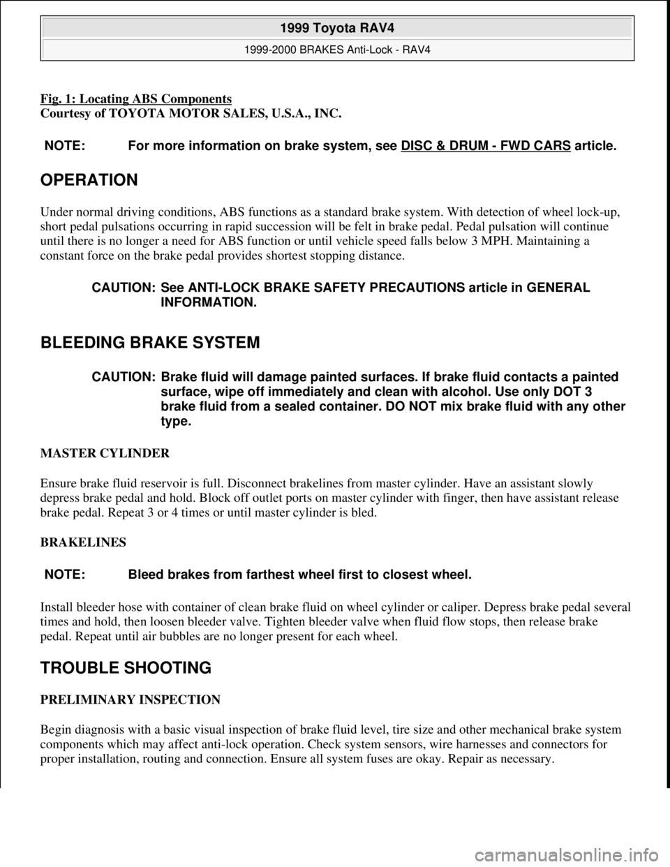
Fig. 1: Locating ABS Components
Courtesy of TOYOTA MOTOR SALES, U.S.A., INC.
OPERATION
Under normal driving conditions, ABS functions as a standard brake system. With detection of wheel lock-up,
short pedal pulsations occurring in rapid succession will be felt in brake pedal. Pedal pulsation will continue
until there is no longer a need for ABS function or until vehicle speed falls below 3 MPH. Maintaining a
constant force on the brake pedal provides shortest stopping distance.
BLEEDING BRAKE SYSTEM
MASTER CYLINDER
Ensure brake fluid reservoir is full. Disconnect brakelines from master cylinder. Have an assistant slowly
depress brake pedal and hold. Block off outlet ports on master cylinder with finger, then have assistant release
brake pedal. Repeat 3 or 4 times or until master cylinder is bled.
BRAKELINES
Install bleeder hose with container of clean brake fluid on wheel cylinder or caliper. Depress brake pedal several
times and hold, then loosen bleeder valve. Tighten bleeder valve when fluid flow stops, then release brake
pedal. Repeat until air bubbles are no longer present for each wheel.
TROUBLE SHOOTING
PRELIMINARY INSPECTION
Begin diagnosis with a basic visual inspection of brake fluid level, tire size and other mechanical brake system
components which may affect anti-lock operation. Check system sensors, wire harnesses and connectors for
proper installation, routing and connection. Ensure all system fuses are okay. Repair as necessary. NOTE: For more information on brake system, see DISC & DRUM
- FWD CARS article.
CAUTION: See ANTI-LOCK BRAKE SAFETY PRECAUTIONS article in GENERAL
INFORMATION.
CAUTION: Brake fluid will damage painted surfaces. If brake fluid contacts a painted
surface, wipe off immediately and clean with alcohol. Use only DOT 3
brake fluid from a sealed container. DO NOT mix brake fluid with any other
type.
NOTE: Bleed brakes from farthest wheel first to closest wheel.
1999 Toyota RAV4
1999-2000 BRAKES Anti-Lock - RAV4
Microsoft
Sunday, November 22, 2009 10:06:17 AMPage 2 © 2005 Mitchell Repair Information Company, LLC.
Page 4 of 1632
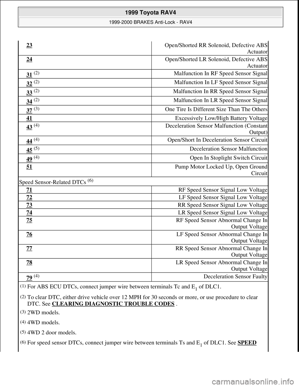
23 Open/Shorted RR Solenoid, Defective ABS
Actuator
24 Open/Shorted LR Solenoid, Defective ABS
Actuator
31 (2) Malfunction In RF Speed Sensor Signal
32 (2) Malfunction In LF Speed Sensor Signal
33 (2) Malfunction In RR Speed Sensor Signal
34 (2) Malfunction In LR Speed Sensor Signal
37 (3) One Tire Is Different Size Than The Others
41 Excessively Low/High Battery Voltage
43 (4) Deceleration Sensor Malfunction (Constant
Output)
44 (4) Open/Short In Deceleration Sensor Circuit
45 (5) Deceleration Sensor Malfunction
49 (4) Open In Stoplight Switch Circuit
51 Pump Motor Locked Up, Open Ground
Circuit
Speed Sensor-Related DTCs (6)
71 RF Speed Sensor Signal Low Voltage
72 LF Speed Sensor Signal Low Voltage
73 RR Speed Sensor Signal Low Voltage
74 LR Speed Sensor Signal Low Voltage
75 RF Speed Sensor Abnormal Change In
Output Voltage
76 LF Speed Sensor Abnormal Change In
Output Voltage
77 RR Speed Sensor Abnormal Change In
Output Voltage
78 LR Speed Sensor Abnormal Change In
Output Voltage
79 (4) Deceleration Sensor Faulty
(1)For ABS ECU DTCs, connect jumper wire between terminals Tc and E1 of DLC1.
(2)To clear DTC, either drive vehicle over 12 MPH for 30 seconds or more, or use procedure to clear
DTC. See CLEARING DIAGNOSTIC TROUBLE CODES
.
(3)2WD models.
(4)4WD models.
(5)4WD 2 door models.
(6)For speed sensor DTCs, connect jumper wire between terminals Ts and E1 of DLC1. See SPEED
1999 Toyota RAV4
1999-2000 BRAKES Anti-Lock - RAV4
Microsoft
Sunday, November 22, 2009 10:06:17 AMPage 4 © 2005 Mitchell Repair Information Company, LLC.
Page 16 of 1632
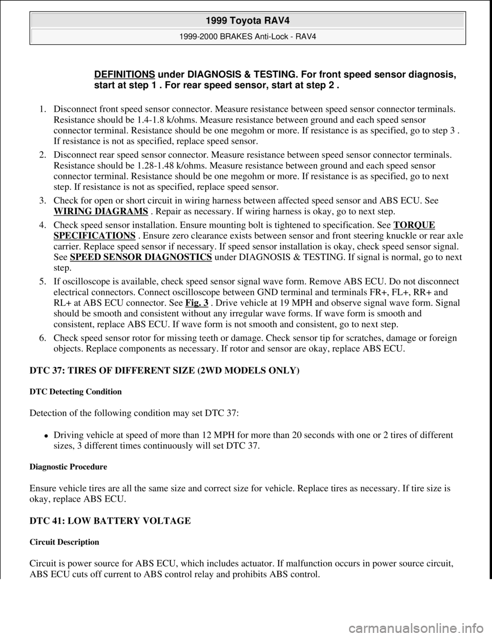
1. Disconnect front speed sensor connector. Measure resistance between speed sensor connector terminals.
Resistance should be 1.4-1.8 k/ohms. Measure resistance between ground and each speed sensor
connector terminal. Resistance should be one megohm or more. If resistance is as specified, go to step 3 .
If resistance is not as specified, replace speed sensor.
2. Disconnect rear speed sensor connector. Measure resistance between speed sensor connector terminals.
Resistance should be 1.28-1.48 k/ohms. Measure resistance between ground and each speed sensor
connector terminal. Resistance should be one megohm or more. If resistance is as specified, go to next
step. If resistance is not as specified, replace speed sensor.
3. Check for open or short circuit in wiring harness between affected speed sensor and ABS ECU. See
WIRING DIAGRAMS
. Repair as necessary. If wiring harness is okay, go to next step.
4. Check speed sensor installation. Ensure mounting bolt is tightened to specification. See TORQUE
SPECIFICATIONS . Ensure zero clearance exists between sensor and front steering knuckle or rear axle
carrier. Replace speed sensor if necessary. If speed sensor installation is okay, check speed sensor signal.
See SPEED SENSOR DIAGNOSTICS
under DIAGNOSIS & TESTING. If signal is normal, go to next
step.
5. If oscilloscope is available, check speed sensor signal wave form. Remove ABS ECU. Do not disconnect
electrical connectors. Connect oscilloscope between GND terminal and terminals FR+, FL+, RR+ and
RL+ at ABS ECU connector. See Fig. 3
. Drive vehicle at 19 MPH and observe signal wave form. Signal
should be smooth and consistent without any irregular wave forms. If wave form is smooth and
consistent, replace ABS ECU. If wave form is not smooth and consistent, go to next step.
6. Check speed sensor rotor for missing teeth or damage. Check sensor tip for scratches, damage or foreign
objects. Replace components as necessary. If rotor and sensor are okay, replace ABS ECU.
DTC 37: TIRES OF DIFFERENT SIZE (2WD MODELS ONLY)
DTC Detecting Condition
Detection of the following condition may set DTC 37:
Driving vehicle at speed of more than 12 MPH for more than 20 seconds with one or 2 tires of different
sizes, 3 different times continuously will set DTC 37.
Diagnostic Procedure
Ensure vehicle tires are all the same size and correct size for vehicle. Replace tires as necessary. If tire size is
okay, replace ABS ECU.
DTC 41: LOW BATTERY VOLTAGE
Circuit Description
Circuit is power source for ABS ECU, which includes actuator. If malfunction occurs in power source circuit,
ABS ECU cuts off current to ABS control relay and prohibits ABS control. DEFINITIONS
under DIAGNOSIS & TESTING. For front speed sensor diagnosis,
start at step 1 . For rear speed sensor, start at step 2 .
1999 Toyota RAV4
1999-2000 BRAKES Anti-Lock - RAV4
Microsoft
Sunday, November 22, 2009 10:06:17 AMPage 16 © 2005 Mitchell Repair Information Company, LLC.
Page 920 of 1632
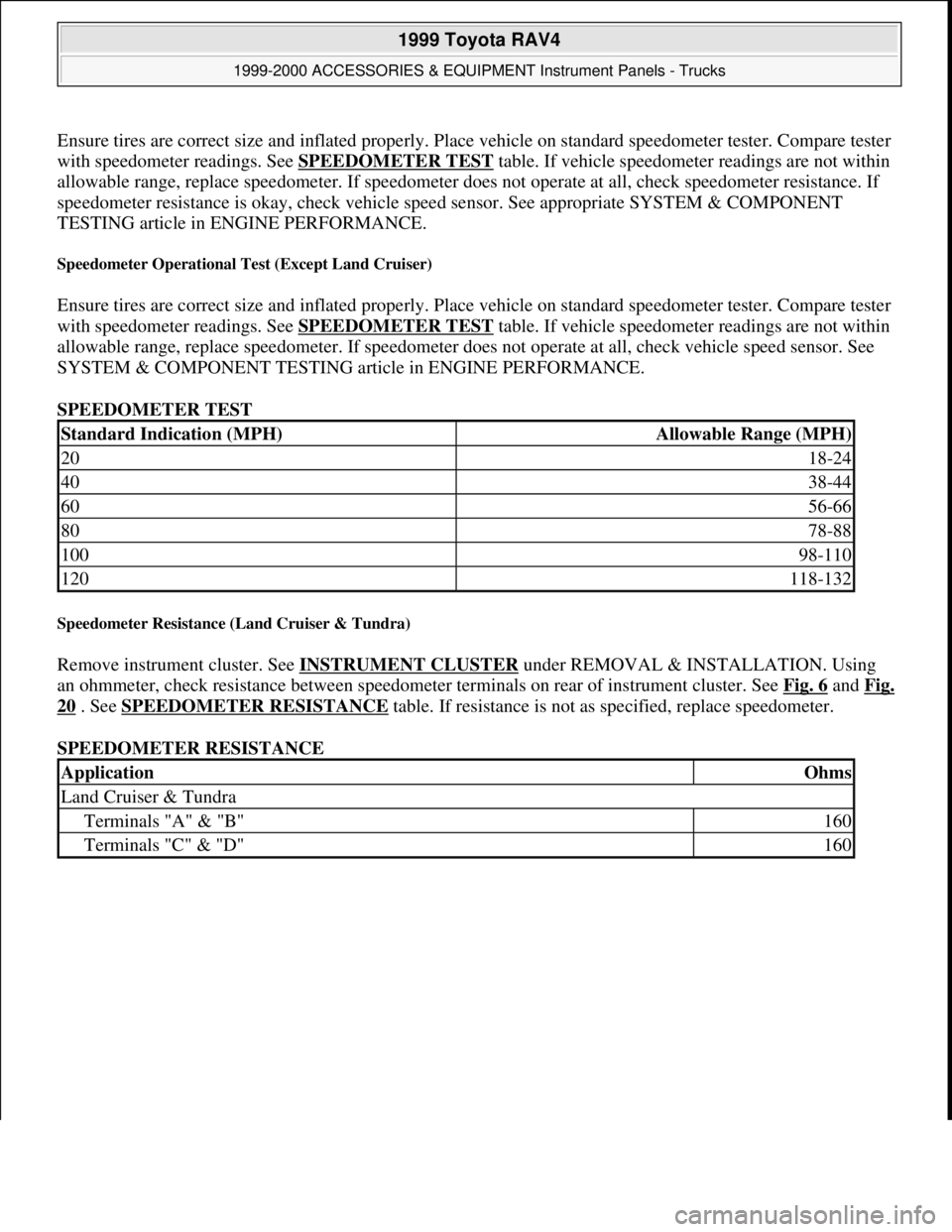
Ensure tires are correct size and inflated properly. Place vehicle on standard speedometer tester. Compare tester
with speedometer readings. See SPEEDOMETER TEST
table. If vehicle speedometer readings are not within
allowable range, replace speedometer. If speedometer does not operate at all, check speedometer resistance. If
speedometer resistance is okay, check vehicle speed sensor. See appropriate SYSTEM & COMPONENT
TESTING article in ENGINE PERFORMANCE.
Speedometer Operational Test (Except Land Cruiser)
Ensure tires are correct size and inflated properly. Place vehicle on standard speedometer tester. Compare tester
with speedometer readings. See SPEEDOMETER TEST
table. If vehicle speedometer readings are not within
allowable range, replace speedometer. If speedometer does not operate at all, check vehicle speed sensor. See
SYSTEM & COMPONENT TESTING article in ENGINE PERFORMANCE.
SPEEDOMETER TEST
Speedometer Resistance (Land Cruiser & Tundra)
Remove instrument cluster. See INSTRUMENT CLUSTER under REMOVAL & INSTALLATION. Using
an ohmmeter, check resistance between speedometer terminals on rear of instrument cluster. See Fig. 6
and Fig.
20 . See SPEEDOMETER RESISTANCE table. If resistance is not as specified, replace speedometer.
SPEEDOMETER RESISTANCE
Standard Indication (MPH)Allowable Range (MPH)
2018-24
4038-44
6056-66
8078-88
10098-110
120118-132
ApplicationOhms
Land Cruiser & Tundra
Terminals "A" & "B"160
Terminals "C" & "D"160
1999 Toyota RAV4
1999-2000 ACCESSORIES & EQUIPMENT Instrument Panels - Trucks
Microsoft
Sunday, November 22, 2009 10:54:10 AMPage 30 © 2005 Mitchell Repair Information Company, LLC.
Page 950 of 1632
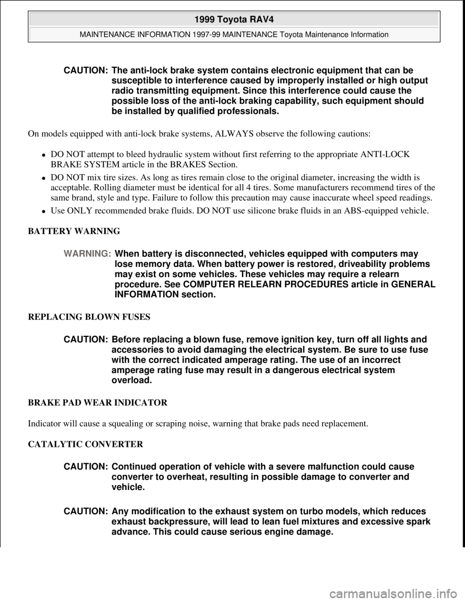
On models equipped with anti-lock brake systems, ALWAYS observe the following cautions:
DO NOT attempt to bleed hydraulic system without first referring to the appropriate ANTI-LOCK
BRAKE SYSTEM article in the BRAKES Section.
DO NOT mix tire sizes. As long as tires remain close to the original diameter, increasing the width is
acceptable. Rolling diameter must be identical for all 4 tires. Some manufacturers recommend tires of the
same brand, style and type. Failure to follow this precaution may cause inaccurate wheel speed readings.
Use ONLY recommended brake fluids. DO NOT use silicone brake fluids in an ABS-equipped vehicle.
BATTERY WARNING
REPLACING BLOWN FUSES
BRAKE PAD WEAR INDICATOR
Indicator will cause a squealing or scraping noise, warning that brake pads need replacement.
CATALYTIC CONVERTER CAUTION: The anti-lock brake system contains electronic equipment that can be
susceptible to interference caused by improperly installed or high output
radio transmitting equipment. Since this interference could cause the
possible loss of the anti-lock braking capability, such equipment should
be installed by qualified professionals.
WARNING:When battery is disconnected, vehicles equipped with computers may
lose memory data. When battery power is restored, driveability problems
may exist on some vehicles. These vehicles may require a relearn
procedure. See COMPUTER RELEARN PROCEDURES article in GENERAL
INFORMATION section.
CAUTION: Before replacing a blown fuse, remove ignition key, turn off all lights and
accessories to avoid damaging the electrical system. Be sure to use fuse
with the correct indicated amperage rating. The use of an incorrect
amperage rating fuse may result in a dangerous electrical system
overload.
CAUTION: Continued operation of vehicle with a severe malfunction could cause
converter to overheat, resulting in possible damage to converter and
vehicle.
CAUTION: Any modification to the exhaust system on turbo models, which reduces
exhaust backpressure, will lead to lean fuel mixtures and excessive spark
advance. This could cause serious engine damage.
1999 Toyota RAV4
MAINTENANCE INFORMATION 1997-99 MAINTENANCE Toyota Maintenance Information
Microsoft
Sunday, November 22, 2009 10:32:42 AMPage 8 © 2005 Mitchell Repair Information Company, LLC.