wheel alignment TOYOTA RAV4 1996 Service Repair Manual
[x] Cancel search | Manufacturer: TOYOTA, Model Year: 1996, Model line: RAV4, Model: TOYOTA RAV4 1996Pages: 1632, PDF Size: 41.64 MB
Page 335 of 1632
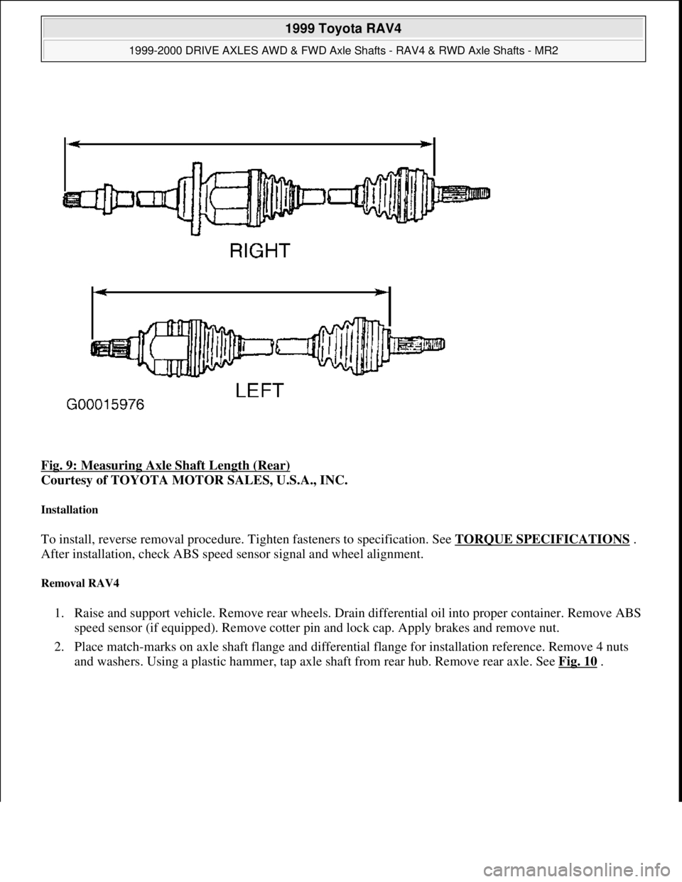
Fig. 9: Measuring Axle Shaft Length (Rear)
Courtesy of TOYOTA MOTOR SALES, U.S.A., INC.
Installation
To install, reverse removal procedure. Tighten fasteners to specification. See TORQUE SPECIFICATIONS .
After installation, check ABS speed sensor signal and wheel alignment.
Removal RAV4
1. Raise and support vehicle. Remove rear wheels. Drain differential oil into proper container. Remove ABS
speed sensor (if equipped). Remove cotter pin and lock cap. Apply brakes and remove nut.
2. Place match-marks on axle shaft flange and differential flange for installation reference. Remove 4 nuts
and washers. Using a plastic hammer, tap axle shaft from rear hub. Remove rear axle. See Fig. 10
.
1999 Toyota RAV4
1999-2000 DRIVE AXLES AWD & FWD Axle Shafts - RAV4 & RWD Axle Shafts - MR2
Microsoft
Sunday, November 22, 2009 10:08:21 AMPage 14 © 2005 Mitchell Repair Information Company, LLC.
Page 337 of 1632
retaining inboard tripod joint. Paint reference marks on tripod joint and axle shaft for reassembly
reference.
3. Using a hammer and brass drift, tap inboard tripod joint from axle shaft. DO NOT tap on roller of tripod
joint during removal. Remove boots from axle shaft. Using a screwdriver and hammer, remove dust
deflector from axle shaft.
Reassembly
1. Using a press, install NEW dust deflector on axle shaft. Wrap splines on axle shaft with tape to prevent
damaging boots during installation.
2. Install NEW boots and NEW boot clamps on axle shaft. Install NEW snap ring on axle shaft. Install
inboard tripod joint on axle shaft, with small diameter side facing outboard joint. Ensure reference mark
on inboard joint and axle shaft are aligned. Install NEW snap ring that retains inboard tripod joint on axle
shaft.
3. Apply grease supplied with overhaul kit to inner joint and boot. Install outer joint tulip on inner joint.
Ensure match-marks are aligned.
4. Apply grease supplied with overhaul kit into outer joint and boot. Install boot on inner housing and outer
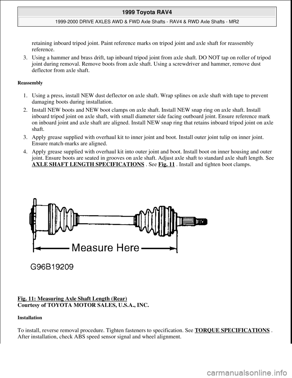
joint. Ensure boots are seated in grooves on axle shaft. Adjust axle shaft to standard axle shaft length. See
AXLE SHAFT LENGTH SPECIFICATIONS
. See Fig. 11 . Install and tighten boot clamps.
Fig. 11: Measuring Axle Shaft Length (Rear)
Courtesy of TOYOTA MOTOR SALES, U.S.A., INC.
Installation
To install, reverse removal procedure. Tighten fasteners to specification. See TORQUE SPECIFICATIONS .
After installation, check ABS speed sensor si
gnal and wheel alignment.
1999 Toyota RAV4
1999-2000 DRIVE AXLES AWD & FWD Axle Shafts - RAV4 & RWD Axle Shafts - MR2
Microsoft
Sunday, November 22, 2009 10:08:21 AMPage 16 © 2005 Mitchell Repair Information Company, LLC.
Page 722 of 1632
17. Ensure slot area on intake camshaft is vertically positioned. Rotate coupling on distributor so cutout
aligns with alignment mark on distributor housing.
18. Install distributor so center of flange on distributor is aligned with bolt hole on cylinder head. Install
distributor hold-down bolt(s). Adjust ignition timing.
CRANKSHAFT REAR OIL SEAL
Removal
Remove transaxle, clutch assembly (if equipped) and flywheel/drive plate. Using a knife, cut seal lip from oil
seal. Pry oil seal from rear seal housing. DO NOT damage sealing surfaces.
Installation
1. Ensure all sealing surfaces are clean. Apply grease to seal lip of new oil seal. Using Oil Seal Installer
(SST 09223-15030), install oil seal into rear seal housing until oil seal is even with surface of rear seal
housing.
2. Apply Loctite to flywheel/drive plate bolts. Install flywheel/drive plate. Install bolts and tighten to
specification using a crisscross pattern. See TORQUE SPECIFICATIONS
. To install remaining
components, reverse removal procedure.
WATER PUMP
Removal
1. Disconnect negative battery cable. Drain cooling system. Remove timing belt and idler pulley(s) as
needed for access to water pump. See TIMING BELT
.
2. Disconnect lower radiator hose from thermostat housing. Remove generator adjusting bracket. Remove
coolant b
y-pass pipe-to-water pump nuts. See Fig. 27. NOTE: On 4WD models, manufacturer recommends removing engine with transaxle for
transaxle removal. On 2WD models, transaxle may be removed with engine in
vehicle.
1999 Toyota RAV4
1999-2000 ENGINES 2.0L 4-Cylinder
Microsoft
Sunday, November 22, 2009 10:22:26 AMPage 39 © 2005 Mitchell Repair Information Company, LLC.
Page 771 of 1632
Removal
1. Disconnect negative battery cable. Remove power steering fluid reservoir with mounting bracket.
Remove accessory drive belts. Remove generator and generator mounting bracket. Remove wiring
brackets for access to timing belt covers.
2. On models with Anti-Lock Brake System (ABS), disconnect electrical connectors and brake lines from
ABS actuator. ABS actuator is located in front of passenger-side strut tower. Remove ABS actuator
mounting bracket-to-body bolts/nuts. Remove ABS actuator with mounting bracket.
3. On all models, raise and support vehicle. Remove passenger-side lower engine cover. Remove passenger-
side front wheel.
4. Using floor jack, slightly raise engine to remove weight from right (timing belt side) engine mount at
timing belt cover. Remove right (timing belt side) engine mount from body and mounting bracket on
cylinder block for access to timing belt covers.
5. Remove spark plugs. Remove crankshaft pulley bolt. Using puller, remove crankshaft pulley. Remove
right (timing belt side) engine mounting bracket from front of cylinder block.
6. Disconnect engine wiring harness protector from rear of No. 2 timing belt cover. When disconnecting
engine wiring harness protector, remove bolt on intake manifold side of engine first and then bolt on
exhaust manifold side of engine.
7. Remove No. 2 timing belt cover. See Fig. 17
. Install crankshaft pulley on crankshaft. Temporarily install
crankshaft pulley bolt.
8. Rotate crankshaft clockwise, viewed from timing belt end of engine, so cylinder No. 1 is at TDC on
compression stroke and timing mark on crankshaft pulley aligns with "0" mark on timing belt cover.
Cylinder No. 1 is front cylinder at timing belt end of engine.
9. Ensure hole in camshaft sprocket aligns with alignment mark on camshaft bearing cap. See Fig. 18
. If
hole in camshaft sprocket is not aligned with alignment mark, rotate crankshaft clockwise one full
revolution.
1997 Toyota RAV4
2.0L 4-CYL 1997-98 ENGINES Toyota 2.0L 4-Cylinder
Microsoft
Sunday, November 22, 2009 10:23:31 AMPage 23 © 2005 Mitchell Repair Information Company, LLC.
Page 787 of 1632
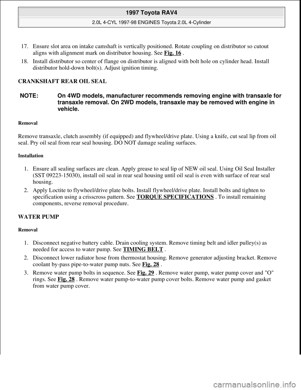
17. Ensure slot area on intake camshaft is vertically positioned. Rotate coupling on distributor so cutout
aligns with alignment mark on distributor housing. See Fig. 16
.
18. Install distributor so center of flange on distributor is aligned with bolt hole on cylinder head. Install
distributor hold-down bolt(s). Adjust ignition timing.
CRANKSHAFT REAR OIL SEAL
Removal
Remove transaxle, clutch assembly (if equipped) and flywheel/drive plate. Using a knife, cut seal lip from oil
seal. Pry oil seal from rear seal housing. DO NOT damage sealing surfaces.
Installation
1. Ensure all sealing surfaces are clean. Apply grease to seal lip of NEW oil seal. Using Oil Seal Installer
(SST 09223-15030), install oil seal in rear seal housing until oil seal is even with surface of rear seal
housing.
2. Apply Loctite to flywheel/drive plate bolts. Install flywheel/drive plate. Install bolts and tighten to
specification using a crisscross pattern. See TORQUE SPECIFICATIONS
. To install remaining
components, reverse removal procedure.
WATER PUMP
Removal
1. Disconnect negative battery cable. Drain cooling system. Remove timing belt and idler pulley(s) as
needed for access to water pump. See TIMING BELT
.
2. Disconnect lower radiator hose from thermostat housing. Remove generator adjusting bracket. Remove
coolant by-pass pipe-to-water pump nuts. See Fig. 28
.
3. Remove water pump bolts in sequence. See Fig. 29
. Remove water pump, water pump cover and "O"
rings. See Fig. 28
. Remove water pump-to-water pump cover bolts. Remove water pump and gasket
from water pump cover. NOTE: On 4WD models, manufacturer recommends removing engine with transaxle for
transaxle removal. On 2WD models, transaxle may be removed with engine in
vehicle.
1997 Toyota RAV4
2.0L 4-CYL 1997-98 ENGINES Toyota 2.0L 4-Cylinder
Microsoft
Sunday, November 22, 2009 10:23:31 AMPage 39 © 2005 Mitchell Repair Information Company, LLC.
Page 819 of 1632
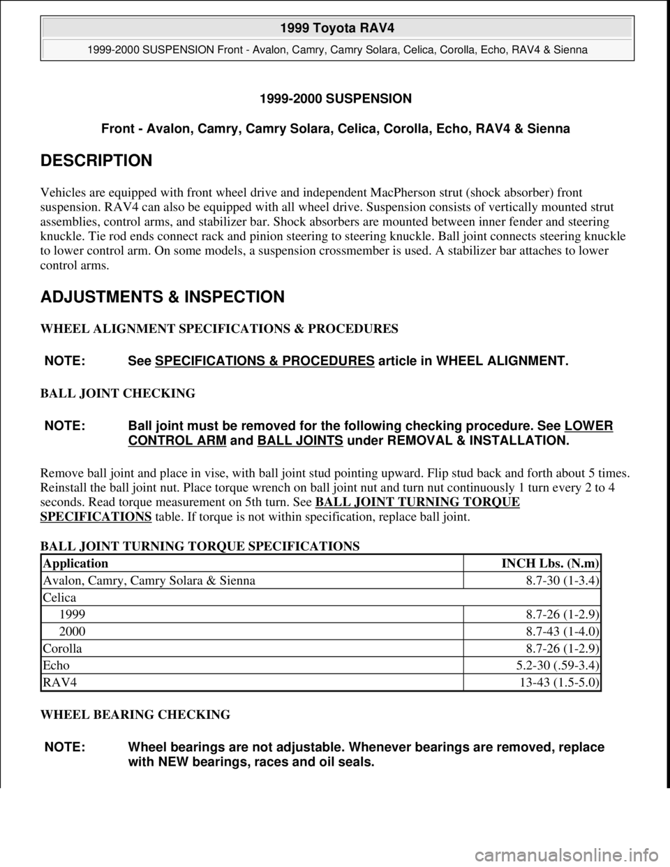
1999-2000 SUSPENSION
Front - Avalon, Camry, Camry Solara, Celica, Corolla, Echo, RAV4 & Sienna
DESCRIPTION
Vehicles are equipped with front wheel drive and independent MacPherson strut (shock absorber) front
suspension. RAV4 can also be equipped with all wheel drive. Suspension consists of vertically mounted strut
assemblies, control arms, and stabilizer bar. Shock absorbers are mounted between inner fender and steering
knuckle. Tie rod ends connect rack and pinion steering to steering knuckle. Ball joint connects steering knuckle
to lower control arm. On some models, a suspension crossmember is used. A stabilizer bar attaches to lower
control arms.
ADJUSTMENTS & INSPECTION
WHEEL ALIGNMENT SPECIFICATIONS & PROCEDURES
BALL JOINT CHECKING
Remove ball joint and place in vise, with ball joint stud pointing upward. Flip stud back and forth about 5 times.
Reinstall the ball joint nut. Place torque wrench on ball joint nut and turn nut continuously 1 turn every 2 to 4
seconds. Read torque measurement on 5th turn. See BALL JOINT TURNING TORQUE
SPECIFICATIONS table. If torque is not within specification, replace ball joint.
BALL JOINT TURNING TORQUE SPECIFICATIONS
WHEEL BEARING CHECKING NOTE: See SPECIFICATIONS & PROCEDURES
article in WHEEL ALIGNMENT.
NOTE: Ball joint must be removed for the following checking procedure. See LOWER
CONTROL ARM and BALL JOINTS under REMOVAL & INSTALLATION.
ApplicationINCH Lbs. (N.m)
Avalon, Camry, Camry Solara & Sienna8.7-30 (1-3.4)
Celica
19998.7-26 (1-2.9)
20008.7-43 (1-4.0)
Corolla8.7-26 (1-2.9)
Echo5.2-30 (.59-3.4)
RAV413-43 (1.5-5.0)
NOTE: Wheel bearings are not adjustable. Whenever bearings are removed, replace
with NEW bearings, races and oil seals.
1999 Toyota RAV4
1999-2000 SUSPENSION Front - Avalon, Camry, Camry Solara, Celica, Corolla, Echo, RAV4 & Sienna
1999 Toyota RAV4
1999-2000 SUSPENSION Front - Avalon, Camry, Camry Solara, Celica, Corolla, Echo, RAV4 & Sienna
Microsoft
Sunday, November 22, 2009 10:36:34 AMPage 1 © 2005 Mitchell Repair Information Company, LLC.
Microsoft
Sunday, November 22, 2009 10:36:38 AMPage 1 © 2005 Mitchell Repair Information Company, LLC.
Page 1099 of 1632
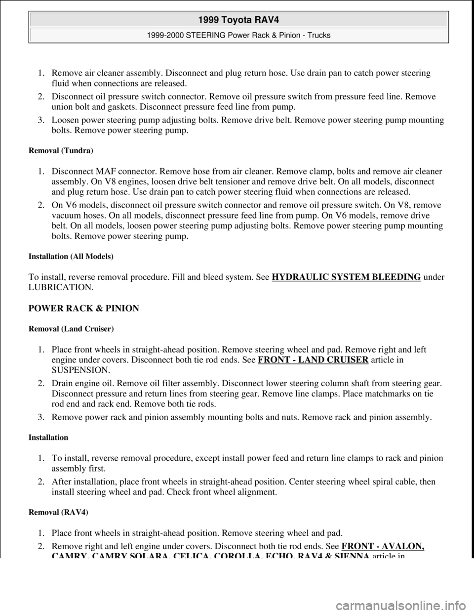
1. Remove air cleaner assembly. Disconnect and plug return hose. Use drain pan to catch power steering
fluid when connections are released.
2. Disconnect oil pressure switch connector. Remove oil pressure switch from pressure feed line. Remove
union bolt and gaskets. Disconnect pressure feed line from pump.
3. Loosen power steering pump adjusting bolts. Remove drive belt. Remove power steering pump mounting
bolts. Remove power steering pump.
Removal (Tundra)
1. Disconnect MAF connector. Remove hose from air cleaner. Remove clamp, bolts and remove air cleaner
assembly. On V8 engines, loosen drive belt tensioner and remove drive belt. On all models, disconnect
and plug return hose. Use drain pan to catch power steering fluid when connections are released.
2. On V6 models, disconnect oil pressure switch connector and remove oil pressure switch. On V8, remove
vacuum hoses. On all models, disconnect pressure feed line from pump. On V6 models, remove drive
belt. On all models, loosen power steering pump adjusting bolts. Remove power steering pump mounting
bolts. Remove power steering pump.
Installation (All Models)
To install, reverse removal procedure. Fill and bleed system. See HYDRAULIC SYSTEM BLEEDINGunder
LUBRICATION.
POWER RACK & PINION
Removal (Land Cruiser)
1. Place front wheels in straight-ahead position. Remove steering wheel and pad. Remove right and left
engine under covers. Disconnect both tie rod ends. See FRONT
- LAND CRUISER article in
SUSPENSION.
2. Drain engine oil. Remove oil filter assembly. Disconnect lower steering column shaft from steering gear.
Disconnect pressure and return lines from steering gear. Remove line clamps. Place matchmarks on tie
rod end and rack end. Remove both tie rods.
3. Remove power rack and pinion assembly mounting bolts and nuts. Remove rack and pinion assembly.
Installation
1. To install, reverse removal procedure, except install power feed and return line clamps to rack and pinion
assembly first.
2. After installation, place front wheels in straight-ahead position. Center steering wheel spiral cable, then
install steering wheel and pad. Check front wheel alignment.
Removal (RAV4)
1. Place front wheels in straight-ahead position. Remove steering wheel and pad.
2. Remove right and left engine under covers. Disconnect both tie rod ends. See FRONT
- AVALON,
CAMRY, CAMRY SOLARA, CELICA, COROLLA, ECHO, RAV4 & SIENNA article in
1999 Toyota RAV4
1999-2000 STEERING Power Rack & Pinion - Trucks
Microsoft
Sunday, November 22, 2009 10:35:46 AMPage 6 © 2005 Mitchell Repair Information Company, LLC.
Page 1100 of 1632
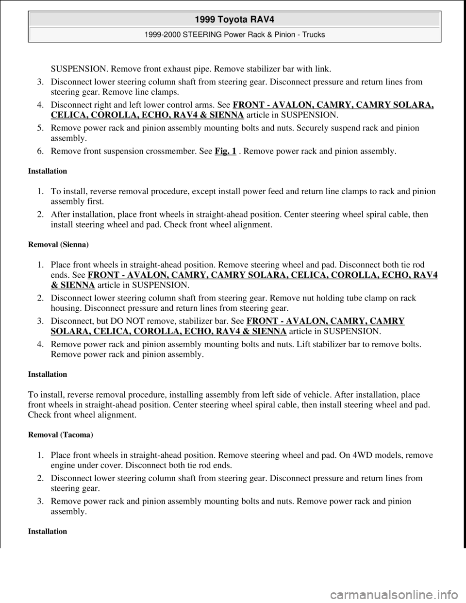
SUSPENSION. Remove front exhaust pipe. Remove stabilizer bar with link.
3. Disconnect lower steering column shaft from steering gear. Disconnect pressure and return lines from
steering gear. Remove line clamps.
4. Disconnect right and left lower control arms. See FRONT
- AVALON, CAMRY, CAMRY SOLARA,
CELICA, COROLLA, ECHO, RAV4 & SIENNA article in SUSPENSION.
5. Remove power rack and pinion assembly mounting bolts and nuts. Securely suspend rack and pinion
assembly.
6. Remove front suspension crossmember. See Fig. 1
. Remove power rack and pinion assembly.
Installation
1. To install, reverse removal procedure, except install power feed and return line clamps to rack and pinion
assembly first.
2. After installation, place front wheels in straight-ahead position. Center steering wheel spiral cable, then
install steering wheel and pad. Check front wheel alignment.
Removal (Sienna)
1. Place front wheels in straight-ahead position. Remove steering wheel and pad. Disconnect both tie rod
ends. See FRONT
- AVALON, CAMRY, CAMRY SOLARA, CELICA, COROLLA, ECHO, RAV4
& SIENNA article in SUSPENSION.
2. Disconnect lower steering column shaft from steering gear. Remove nut holding tube clamp on rack
housing. Disconnect pressure and return lines from steering gear.
3. Disconnect, but DO NOT remove, stabilizer bar. See FRONT
- AVALON, CAMRY, CAMRY
SOLARA, CELICA, COROLLA, ECHO, RAV4 & SIENNA article in SUSPENSION.
4. Remove power rack and pinion assembly mounting bolts and nuts. Lift stabilizer bar to remove bolts.
Remove power rack and pinion assembly.
Installation
To install, reverse removal procedure, installing assembly from left side of vehicle. After installation, place
front wheels in straight-ahead position. Center steering wheel spiral cable, then install steering wheel and pad.
Check front wheel alignment.
Removal (Tacoma)
1. Place front wheels in straight-ahead position. Remove steering wheel and pad. On 4WD models, remove
engine under cover. Disconnect both tie rod ends.
2. Disconnect lower steering column shaft from steering gear. Disconnect pressure and return lines from
steering gear.
3. Remove power rack and pinion assembly mounting bolts and nuts. Remove power rack and pinion
assembly.
Installation
1999 Toyota RAV4
1999-2000 STEERING Power Rack & Pinion - Trucks
Microsoft
Sunday, November 22, 2009 10:35:46 AMPage 7 © 2005 Mitchell Repair Information Company, LLC.
Page 1101 of 1632
To install, reverse removal procedure. After installation, place front wheels in straight-ahead position. Center
steering wheel spiral cable, then install steering wheel and pad. Check front wheel alignment.
Removal (Tundra)
1. Place front wheels in straight-ahead position. Remove steering wheel and pad. Disconnect both tie rod
ends. Disconnect lower steering column shaft from steering gear. Remove clamp plate bolt and remove
clamp plate.
2. Disconnect pressure and return lines from steering gear. Remove power rack and pinion assembly
mounting bolts and nuts. Remove power rack and pinion assembly.
Installation
To install, reverse removal procedure. After installation, place front wheels in straight-ahead position. Center
steering wheel spiral cable, then install steering wheel and pad. Check front wheel alignment.
Removal (4Runner)
1. Place front wheels in straight-ahead position. Remove steering wheel and pad. Remove engine under
cover.
2. Remove stabilizer bar. Disconnect both tie rod ends. Disconnect lower steering column shaft from
steering gear. Disconnect pressure and return lines from steering gear.
3. Remove power rack and pinion assembly mounting bolts and nuts. Remove power rack and pinion
assembly.
Installation
To install, reverse removal procedure. After installation, place front wheels in straight-ahead position. Center
steering wheel spiral cable, then install steering wheel and pad. Check front wheel alignment.
OVERHAUL
POWER STEERING PUMP
Disassembly (RAV4)
1. Mount pump assembly in soft-jaw vise. Ensure pump rotates smoothly. Using a torque wrench, check
pump rotating torque. Rotating torque should be 2.4 INCH lbs. (.3 N.m) or less. Remove front bracket
and pump bracket.
2. While holding pulley, remove pulley nut. Remove pulley and Woodruff key from pump shaft. Remove air
control valve. See Fig. 3
. Remove pressure feed No. 2 tube.
3. Remove union bolt and "O" ring from suction (return) port. Remove "O" ring from pressure port. Remove
flow control valve and spring. See Fig. 3
.
4. Remove flow control valve seat snap ring. Install a 6 x 1 x 50 mm bolt about 2-3 threads into seat. Pull
sprin
g seat from housing. Remove "O" ring.
1999 Toyota RAV4
1999-2000 STEERING Power Rack & Pinion - Trucks
Microsoft
Sunday, November 22, 2009 10:35:46 AMPage 8 © 2005 Mitchell Repair Information Company, LLC.
Page 1142 of 1632
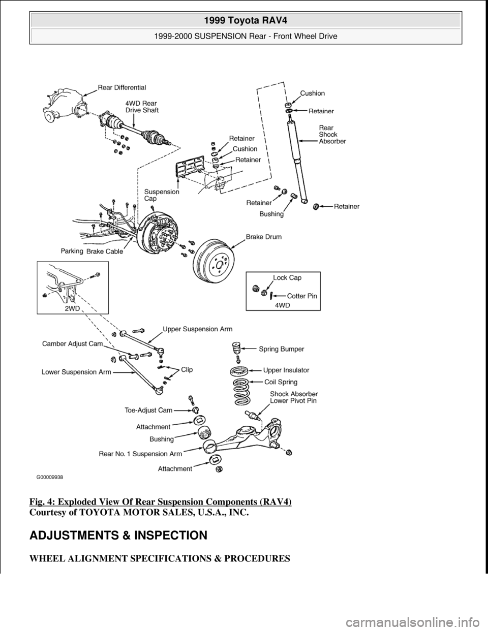
Fig. 4: Exploded View Of Rear Suspension Components (RAV4)
Courtesy of TOYOTA MOTOR SALES, U.S.A., INC.
ADJUSTMENTS & INSPECTION
WHEEL ALIGNMENT SPECIFICATIONS & PROCEDURES
1999 Toyota RAV4
1999-2000 SUSPENSION Rear - Front Wheel Drive
Microsoft
Sunday, November 22, 2009 10:37:21 AMPage 4 © 2005 Mitchell Repair Information Company, LLC.