wheel torque TOYOTA RAV4 1996 Service Repair Manual
[x] Cancel search | Manufacturer: TOYOTA, Model Year: 1996, Model line: RAV4, Model: TOYOTA RAV4 1996Pages: 1632, PDF Size: 41.64 MB
Page 29 of 1632
Fig. 11: Exploded View of ABS Actuator
Courtesy of TOYOTA MOTOR SALES, U.S.A., INC.
ABS ECU
Removal & Installation
Ensure ignition is off. Disconnect negative battery cable. Access ABS ECU, located at right side of passenger
compartment. See Fig. 1
. Disconnect ABS ECU connectors. Remove ABS ECU from vehicle. To install,
reverse removal procedure.
FRONT SENSOR ROTOR
Removal & Installation
Front sensor is part of front hub. For removal and installation of front hub, see AXLE SHAFTS - RAV4 article
in DRIVE AXLES.
REAR SENSOR ROTOR
Removal & Installation
Rear sensor rotor is pressed onto axle shaft. For axle shaft removal and installation procedure, see AXLE
SHAFTS - RAV4 article in DRIVE AXLES.
FRONT WHEEL SPEED SENSORS
Removal & Installation
1. Raise and support front of vehicle. Remove front wheel. Remove inner fender panel. Disconnect wheel
speed sensor connector. Remove clamp bolts holding sensor harness to body, strut assembly and steering
knuckle.
2. Remove wheel speed sensor mounting bolt. Remove wheel speed sensor from steering knuckle. To
install, reverse removal procedure. Ensure wheel speed sensor is flat against knuckle when bolt is
tightened. Tighten wheel speed sensor mounting bolt to specification. See TORQUE
SPECIFICATIONS .
REAR WHEEL SPEED SENSORS
Removal & Installation
1. Remove rear seat cushion and side trim panel. Raise and support vehicle. Remove wheel. Unplug wheel
speed sensor connector and remove wire harness from grommet. Disconnect parking brake cable from
suspension arm. Remove clamp bolts holding sensor wiring harness to body and suspension arm.
2. Remove wheel speed sensor. To install, reverse removal procedure. Ensure wheel speed sensor is flat NOTE: Front hub must be removed to service sensor rotor.
1999 Toyota RAV4
1999-2000 BRAKES Anti-Lock - RAV4
Microsoft
Sunday, November 22, 2009 10:06:17 AMPage 29 © 2005 Mitchell Repair Information Company, LLC.
Page 30 of 1632
against knuckle when bolt is tightened. Tighten wheel speed sensor and brake components to
specification. See TORQUE SPECIFICATIONS
.
ADJUSTMENTS
BRAKE BOOSTER PUSH ROD
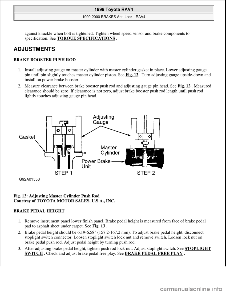
1. Install adjusting gauge on master cylinder with master cylinder gasket in place. Lower adjusting gauge
pin until pin slightly touches master cylinder piston. See Fig. 12
. Turn adjusting gauge upside-down and
install on power brake booster.
2. Measure clearance between brake booster push rod and adjusting gauge pin head. See Fig. 12
. Measured
clearance should be zero. If clearance is not zero, adjust brake booster push rod length until push rod
lightly touches adjusting gauge pin head.
Fig. 12: Adjusting Master Cylinder Push Rod
Courtesy of TOYOTA MOTOR SALES, U.S.A., INC.
BRAKE PEDAL HEIGHT
1. Remove instrument panel lower finish panel. Brake pedal height is measured from face of brake pedal
pad to asphalt sheet under carpet. See Fig. 13
.
2. Brake pedal height should be 6.19-6.58" (157.2-167.2 mm). To adjust brake pedal height, disconnect
stoplight switch connector. Loosen stoplight switch lock nut and remove switch. Loosen lock nut on
brake pedal push rod. Adjust pedal height by turning push rod.
3. After adjusting brake pedal height, tighten push rod lock nut. Adjust stoplight switch. See STOPLIGHT
SWITCH . Check and adjust brake pedal free play. See BRAKE PEDAL FREE PLAY.
1999 Toyota RAV4
1999-2000 BRAKES Anti-Lock - RAV4
Microsoft
Sunday, November 22, 2009 10:06:17 AMPage 30 © 2005 Mitchell Repair Information Company, LLC.
Page 32 of 1632
Brake pedal depressed height is measured from face of brake pedal pad to asphalt sheet under carpet with
brakes applied. Measure brake pedal depressed height with engine running and weight of 110 lbs. (50 kg)
applied against brake pedal. Minimum brake pedal depressed height should be 2.95" (75.0 mm). If measured
distance is less than minimum height, inspect brake system.
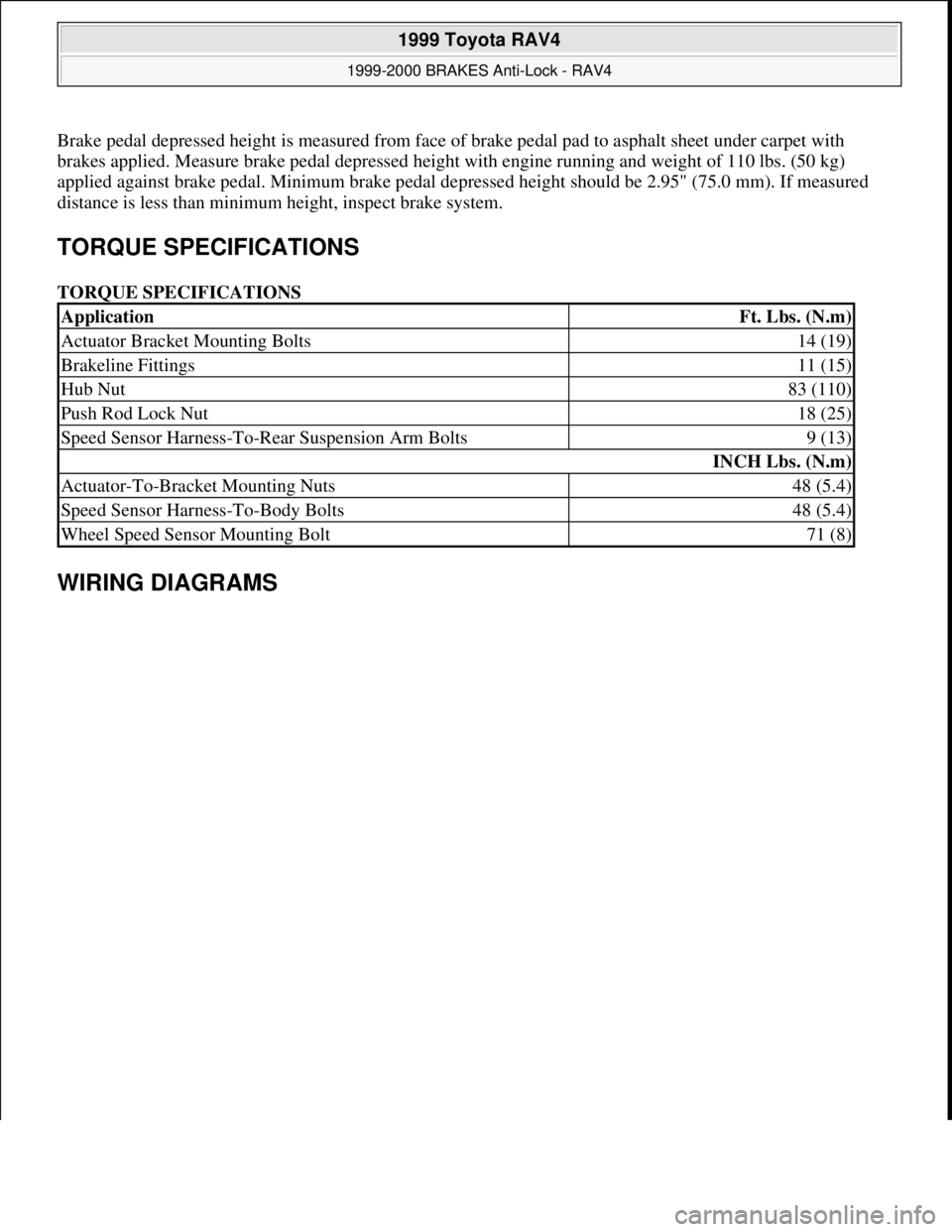
TORQUE SPECIFICATIONS
TORQUE SPECIFICATIONS
WIRING DIAGRAMS
ApplicationFt. Lbs. (N.m)
Actuator Bracket Mounting Bolts14 (19)
Brakeline Fittings11 (15)
Hub Nut83 (110)
Push Rod Lock Nut18 (25)
Speed Sensor Harness-To-Rear Suspension Arm Bolts9 (13)
INCH Lbs. (N.m)
Actuator-To-Bracket Mounting Nuts48 (5.4)
Speed Sensor Harness-To-Body Bolts48 (5.4)
Wheel Speed Sensor Mounting Bolt71 (8)
1999 Toyota RAV4
1999-2000 BRAKES Anti-Lock - RAV4
Microsoft
Sunday, November 22, 2009 10:06:17 AMPage 32 © 2005 Mitchell Repair Information Company, LLC.
Page 45 of 1632
1. Before proceeding, see SERVICE PRECAUTIONS . Disable SRS. See DISABLING &
ACTIVATING AIR BAG SYSTEM .
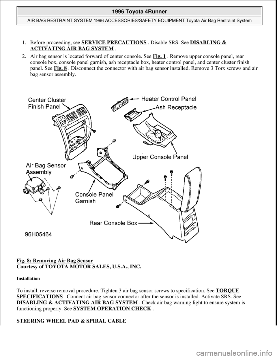
2. Air bag sensor is located forward of center console. See Fig. 1
. Remove upper console panel, rear
console box, console panel garnish, ash receptacle box, heater control panel, and center cluster finish
panel. See Fig. 8
. Disconnect the connector with air bag sensor installed. Remove 3 Torx screws and air
bag sensor assembly.
Fig. 8: Removing Air Bag Sensor
Courtesy of TOYOTA MOTOR SALES, U.S.A., INC.
Installation
To install, reverse removal procedure. Tighten 3 air bag sensor screws to specification. See TORQUE
SPECIFICATIONS . Connect air bag sensor connector after the sensor is installed. Activate SRS. See
DISABLING & ACTIVATING AIR BAG SYSTEM
. Check air bag warning light to ensure system is
functioning properly. See SYSTEM OPERATION CHECK
.
STEERING WHEEL PAD & SPIRAL CABLE
1996 Toyota 4Runner
AIR BAG RESTRAINT SYSTEM 1996 ACCESSORIES/SAFETY EQUIPMENT Toyota Air Bag Restraint System
Microsoft
Tuesday, August 18, 2009 7:33:32 PMPage 11 © 2005 Mitchell Repair Information Company, LLC.
Page 47 of 1632
Installation
To install, reverse removal procedure. Ensure spiral cable is properly aligned. See SPIRAL CABLE under
ADJUSTMENTS. Connect air bag connector. Tighten 2 Torx screws to specification. See TORQUE
SPECIFICATIONS . Install steering wheel side covers. Perform SYSTEM OPERATION CHECK .
PASSENGER-SIDE AIR BAG
Removal & Installation
1. Before proceeding, follow air bag service precautions. See SERVICE PRECAUTIONS . Turn ignition
switch to LOCK position. Disconnect and shield negative battery cable. Wait at least 90 seconds before
working on system.
2. Disable SRS. See DISABLING & ACTIVATING AIR BAG SYSTEM
. Remove instrument panel.
Remove the 2 bolts securing passenger-side air bag. See Fig. 10
. Remove air bag. Remove 3 bolts and
pry up the 5 air bag door clips and remove the air bag door. See Fig. 11
.
3. To install, reverse removal procedure. Tighten passenger-side air bag bolts to specification. See
TORQUE SPECIFICATIONS
. Activate SRS. See DISABLING & ACTIVATING AIR BAG
SYSTEM . Check air bag warning light to ensure system is functioning properly. See SYSTEM
OPERATION CHECK . WARNING:During installation, if spiral cable mating mark is not properly aligned,
steering wheel may not turn completely, or flat cable inside spiral cable
may be severed, disabling SRS system.
1996 Toyota 4Runner
AIR BAG RESTRAINT SYSTEM 1996 ACCESSORIES/SAFETY EQUIPMENT Toyota Air Bag Restraint System
Microsoft
Tuesday, August 18, 2009 7:33:32 PMPage 13 © 2005 Mitchell Repair Information Company, LLC.
Page 60 of 1632
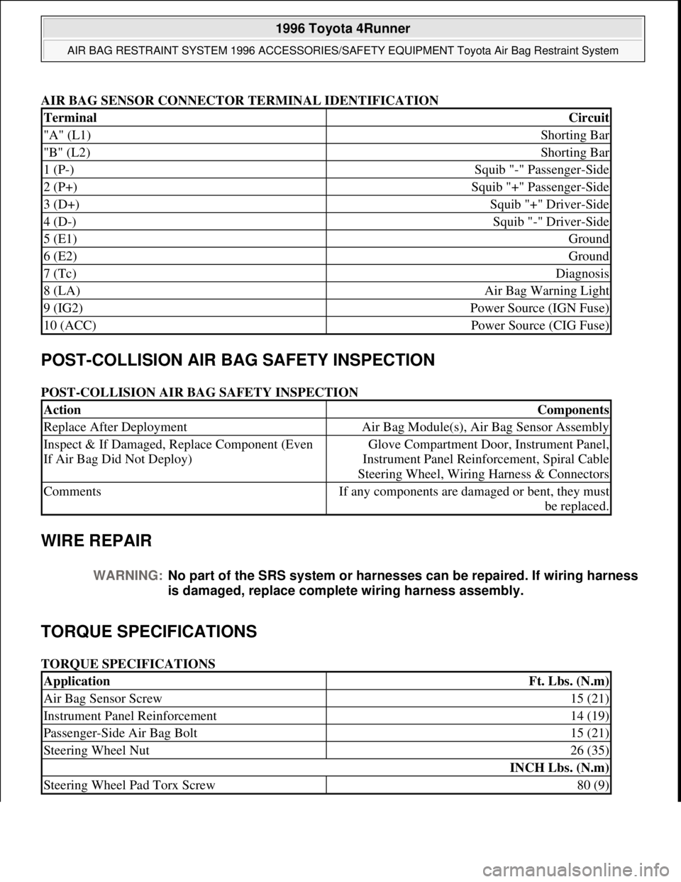
AIR BAG SENSOR CONNECTOR TERMINAL IDENTIFICATION
POST-COLLISION AIR BAG SAFETY INSPECTION
POST-COLLISION AIR BAG SAFETY INSPECTION
WIRE REPAIR
TORQUE SPECIFICATIONS
TORQUE SPECIFICATIONS
TerminalCircuit
"A" (L1)Shorting Bar
"B" (L2)Shorting Bar
1 (P-)Squib "-" Passenger-Side
2 (P+)Squib "+" Passenger-Side
3 (D+)Squib "+" Driver-Side
4 (D-)Squib "-" Driver-Side
5 (E1)Ground
6 (E2)Ground
7 (Tc)Diagnosis
8 (LA)Air Bag Warning Light
9 (IG2)Power Source (IGN Fuse)
10 (ACC)Power Source (CIG Fuse)
ActionComponents
Replace After DeploymentAir Bag Module(s), Air Bag Sensor Assembly
Inspect & If Damaged, Replace Component (Even
If Air Bag Did Not Deploy)Glove Compartment Door, Instrument Panel,
Instrument Panel Reinforcement, Spiral Cable
Steering Wheel, Wiring Harness & Connectors
CommentsIf any components are damaged or bent, they must
be replaced.
WARNING:No part of the SRS system or harnesses can be repaired. If wiring harness
is damaged, replace complete wiring harness assembly.
ApplicationFt. Lbs. (N.m)
Air Bag Sensor Screw15 (21)
Instrument Panel Reinforcement14 (19)
Passenger-Side Air Bag Bolt15 (21)
Steering Wheel Nut26 (35)
INCH Lbs. (N.m)
Steering Wheel Pad Torx Screw80 (9)
1996 Toyota 4Runner
AIR BAG RESTRAINT SYSTEM 1996 ACCESSORIES/SAFETY EQUIPMENT Toyota Air Bag Restraint System
Microsoft
Tuesday, August 18, 2009 7:33:32 PMPage 26 © 2005 Mitchell Repair Information Company, LLC.
Page 78 of 1632
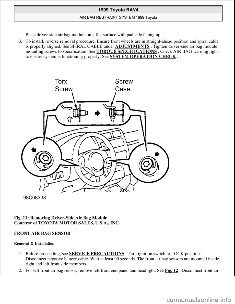
Place driver-side air bag module on a flat surface with pad side facing up.
3. To install, reverse removal procedure. Ensure front wheels are in straight-ahead position and spiral cable
is properly aligned. See SPIRAL CABLE under ADJUSTMENTS
. Tighten driver-side air bag module
mounting screws to specification. See TORQUE SPECIFICATIONS
. Check AIR BAG warning light
to ensure system is functioning properly. See SYSTEM OPERATION CHECK
.
Fig. 11: Removing Driver
-Side Air Bag Module
Courtesy of TOYOTA MOTOR SALES, U.S.A., INC.
FRONT AIR BAG SENSOR
Removal & Installation
1. Before proceeding, see SERVICE PRECAUTIONS . Turn ignition switch to LOCK position.
Disconnect negative battery cable. Wait at least 90 seconds. The front air bag sensors are mounted inside
right and left front side members.
2. For left front air ba
g sensor, remove left front end panel and headlight. See Fig. 12 . Disconnect front air
1999 Toyota RAV4
AIR BAG RESTRAINT SYSTEM 1999 Toyota
Microsoft
Sunday, November 22, 2009 10:33:22 AMPage 15 © 2005 Mitchell Repair Information Company, LLC.
Page 80 of 1632
INSTRUMENT PANEL
Removal & Installation
1. Before proceeding, see SERVICE PRECAUTIONS . Turn ignition switch to LOCK position.
Disconnect negative battery cable. Wait at least 90 seconds.
2. Access and disconnect right and left seat belt pretensioner connectors. See SEAT BELT
PRETENSIONERS . Remove front door scuff plates and cowl side trim boards. See Fig. 13 . Remove
steering wheel. See STEERING WHEEL
. Remove steering column covers and cluster finish panel.
Remove instrument cluster. Remove hood lock release lever.
3. Remove lower finish panel and instrument panel lower insert. Remove No. 2 heater-to-register duct.
Remove steering column assembly. See STEERING COLUMN
. Remove 2 screws and center cluster
finish panel. Pull off heater control knobs and pry off heater control name plate. Pry off cluster instrument
panel, then remove 3 screws from heater control assembly. Disconnect connectors and remove cluster
instrument panel.
4. Disconnect control cables and remove heater control assembly. Remove radio assembly. Remove console
box. Tape tip of screwdriver and remove lower center cluster finish panel. Disconnect connectors.
Remove stereo opening cover. Remove glove box assembly. Remove side trim cover. Disconnect
remaining connectors and remove bolts, then remove instrument panel.
5. To install, reverse removal procedure. Tighten fasteners to specification. See TORQUE
SPECIFICATIONS . Check AIR BAG warning light to ensure system is functioning properly. See
SYSTEM OPERATION CHECK
.
1999 Toyota RAV4
AIR BAG RESTRAINT SYSTEM 1999 Toyota
Microsoft
Sunday, November 22, 2009 10:33:22 AMPage 17 © 2005 Mitchell Repair Information Company, LLC.
Page 82 of 1632
Removal & Installation
1. Before proceeding, see SERVICE PRECAUTIONS . Turn ignition switch to LOCK position.
Disconnect negative battery cable. Wait at least 90 seconds.
2. Remove glove box door. Disconnect passenger-side air bag module connector. See Fig. 3
. Remove
instrument panel. See INSTRUMENT PANEL
. Working from reverse side of instrument panel, remove
2 bolts and passenger-side air bag module. Remove 3 bolts and pry up 7 clips and remove air bag door.
3. To install, reverse removal procedure. Tighten passenger-side air bag bolts to specification. See
TORQUE SPECIFICATIONS
. There should be no interference between passenger-side air bag door
and instrument panel and clearance should be uniform. Check AIR BAG warning light to ensure system
is functioning properly. See SYSTEM OPERATION CHECK
.
SEAT BELT PRETENSIONERS
Removal & Installation
1. Before proceeding, see SERVICE PRECAUTIONS . Turn ignition switch to LOCK position.
Disconnect negative battery cable. Wait at least 90 seconds.
2. On 2-door models, remove rear seat, rear floor finish panel front door scuff plate, quarter trim and roof
side inner garnish. On 4-door models, remove rear door scuff plate, front door scuff plate and center pillar
lower garnish.
3. On all models, remove bolts and floor anchor. Tape tip of screwdriver and remove seat belt assembly
anchor caps. Remove bolt and shoulder anchor. Disconnect pretensioner connector. Remove 2 bolts and
seat belt pretensioner assembly.
4. To install, reverse removal procedure. Tighten fasteners to specification. See TORQUE
SPECIFICATIONS . Check AIR BAG warning light to ensure system is functioning properly. See
SYSTEM OPERATION CHECK
.
SPIRAL CABLE
Removal & Installation
1. Before proceeding, see SERVICE PRECAUTIONS . Turn ignition switch to LOCK position.
Disconnect negative battery cable. Wait at least 90 seconds. Remove driver-side air bag module. See
DRIVER
-SIDE AIR BAG MODULE .
2. Remove steering wheel. See STEERING WHEEL
. Remove lower steering column cover. Disconnect
lower spiral cable connector. Remove 4 screws and spiral cable.
3. To install, reverse removal procedure. Before installing spiral cable, ensure front wheels are in straight-
ahead position and spiral cable is properly aligned. See SPIRAL CABLE under ADJUSTMENTS
.
Tighten steering wheel nut and driver-side air bag module screws to specification. See TORQUE
SPECIFICATIONS . Check AIR BAG warning light to ensure system is functioning properly. See
SYSTEM OPERATION CHECK
.
STEERING COLUMN
Removal & Installation
1999 Toyota RAV4
AIR BAG RESTRAINT SYSTEM 1999 Toyota
Microsoft
Sunday, November 22, 2009 10:33:22 AMPage 19 © 2005 Mitchell Repair Information Company, LLC.
Page 83 of 1632
1. Before proceeding, see SERVICE PRECAUTIONS . Ensure front wheels are in straight-ahead position.
Turn ignition switch to LOCK position. Disconnect negative battery cable. Wait at least 90 seconds.
Remove steering wheel. See STEERING WHEEL
.
2. Remove lower finish panel and instrument panel lower insert. Remove upper and lower steering column
covers. Disconnect and remove combination switch with spiral cable attached. Remove heater-to-register
duct. Match mark steering shaft and steering gear shaft for reassembly performance. Remove steering
column.
3. To install, reverse removal procedure. Tighten fasteners to specification. See TORQUE
SPECIFICATIONS . Check AIR BAG warning light to ensure system is functioning properly. See
SYSTEM OPERATION CHECK
.
STEERING WHEEL
Removal & Installation
1. Before proceeding, see SERVICE PRECAUTIONS . Ensure front wheels are in straight-ahead position.
Turn ignition switch to LOCK position. Disconnect negative battery cable. Wait at least 90 seconds.
Remove driver-side air bag module. See DRIVER
-SIDE AIR BAG MODULE .
2. Remove steering wheel nut. Match mark steering wheel and steering column for reassembly reference.
Using appropriate puller, remove steering wheel.
3. To install, reverse removal procedure. Ensure front wheels are in straight-ahead position and spiral cable
is properly aligned. See SPIRAL CABLE under ADJUSTMENTS
. Tighten steering wheel nut and
driver-side air bag module screws to specification. See TORQUE SPECIFICATIONS
. Check AIR
BAG warning light to ensure system is functioning properly. See SYSTEM OPERATION CHECK
.
SYSTEM OPERATION CHECK
Turn ignition switch to ACC or ON position. AIR BAG warning light should come on for about 6 seconds and
then go out. If AIR BAG warning light does not operate as specified, see DIAGNOSIS & TESTING
.
DIAGNOSIS & TESTING
AIR BAG WARNING LIGHT CHECK
Turn ignition switch to ACC or ON position. If air bag warning light comes on for about 6 seconds and then
goes off, system is functioning properly. If AIR BAG warning light comes on and stays on (or flashes),
Diagnostic Trouble Code (DTC) is stored in air bag sensor assembly. Go to RETRIEVING CODES
. If AIR
BAG warning light responds in any other way, go to DIAGNOSTIC TESTS
.
RETRIEVING CODES
CAUTION: System may be damaged if jumper wire is incorrectly connected across
terminals of Data Link Connector (DLC1). Use Diagnosis Check Wire
(09843-18020) when connecting terminals of DLC1.
1999 Toyota RAV4
AIR BAG RESTRAINT SYSTEM 1999 Toyota
Microsoft
Sunday, November 22, 2009 10:33:22 AMPage 20 © 2005 Mitchell Repair Information Company, LLC.