Oil drain TOYOTA RAV4 2006 Service Owner's Manual
[x] Cancel search | Manufacturer: TOYOTA, Model Year: 2006, Model line: RAV4, Model: TOYOTA RAV4 2006Pages: 2000, PDF Size: 45.84 MB
Page 652 of 2000
2AZ-FE ENGINE MECHANICAL – ENGINE UNITEM–125
EM
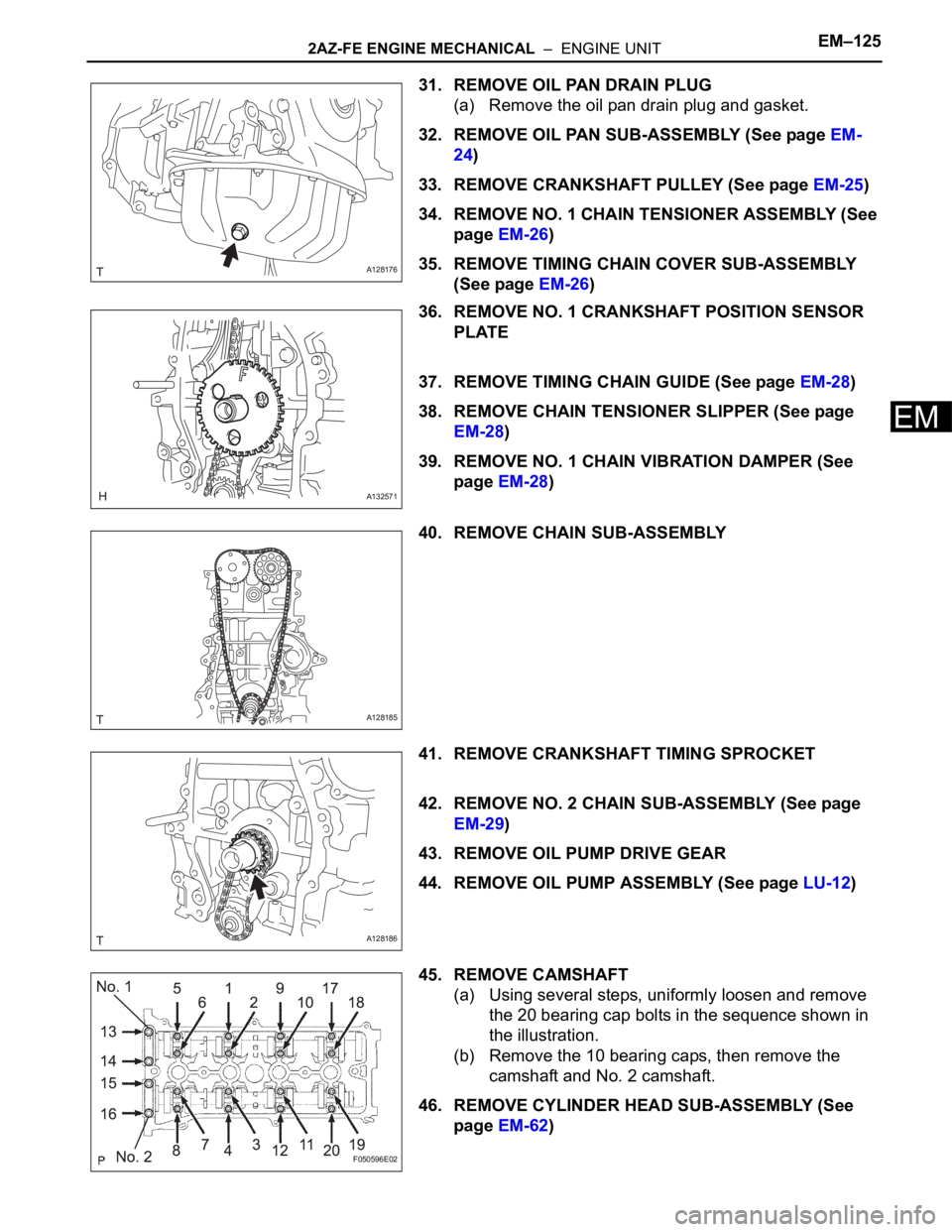
31. REMOVE OIL PAN DRAIN PLUG
(a) Remove the oil pan drain plug and gasket.
32. REMOVE OIL PAN SUB-ASSEMBLY (See page EM-
24)
33. REMOVE CRANKSHAFT PULLEY (See page EM-25)
34. REMOVE NO. 1 CHAIN TENSIONER ASSEMBLY (See
page EM-26)
35. REMOVE TIMING CHAIN COVER SUB-ASSEMBLY
(See page EM-26)
36. REMOVE NO. 1 CRANKSHAFT POSITION SENSOR
PLATE
37. REMOVE TIMING CHAIN GUIDE (See page EM-28)
38. REMOVE CHAIN TENSIONER SLIPPER (See page
EM-28)
39. REMOVE NO. 1 CHAIN VIBRATION DAMPER (See
page EM-28)
40. REMOVE CHAIN SUB-ASSEMBLY
41. REMOVE CRANKSHAFT TIMING SPROCKET
42. REMOVE NO. 2 CHAIN SUB-ASSEMBLY (See page
EM-29)
43. REMOVE OIL PUMP DRIVE GEAR
44. REMOVE OIL PUMP ASSEMBLY (See page LU-12)
45. REMOVE CAMSHAFT
(a) Using several steps, uniformly loosen and remove
the 20 bearing cap bolts in the sequence shown in
the illustration.
(b) Remove the 10 bearing caps, then remove the
camshaft and No. 2 camshaft.
46. REMOVE CYLINDER HEAD SUB-ASSEMBLY (See
page EM-62)
A128176
A132571
A128185
A128186
F050596E02
Page 653 of 2000
EM–1262AZ-FE ENGINE MECHANICAL – ENGINE UNIT
EM
47. REMOVE CYLINDER HEAD GASKET
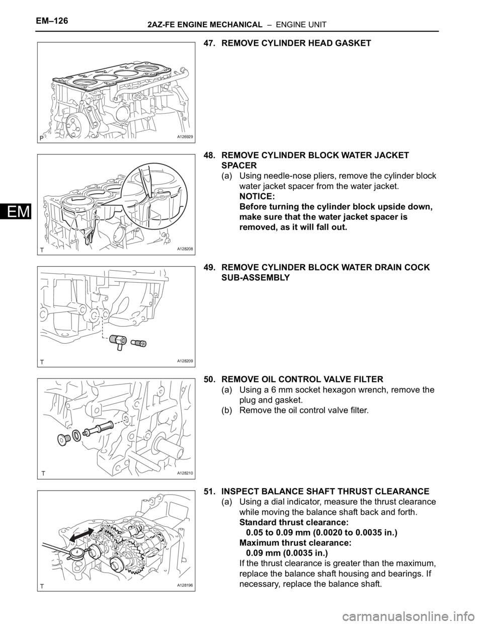
48. REMOVE CYLINDER BLOCK WATER JACKET
SPACER
(a) Using needle-nose pliers, remove the cylinder block
water jacket spacer from the water jacket.
NOTICE:
Before turning the cylinder block upside down,
make sure that the water jacket spacer is
removed, as it will fall out.
49. REMOVE CYLINDER BLOCK WATER DRAIN COCK
SUB-ASSEMBLY
50. REMOVE OIL CONTROL VALVE FILTER
(a) Using a 6 mm socket hexagon wrench, remove the
plug and gasket.
(b) Remove the oil control valve filter.
51. INSPECT BALANCE SHAFT THRUST CLEARANCE
(a) Using a dial indicator, measure the thrust clearance
while moving the balance shaft back and forth.
Standard thrust clearance:
0.05 to 0.09 mm (0.0020 to 0.0035 in.)
Maximum thrust clearance:
0.09 mm (0.0035 in.)
If the thrust clearance is greater than the maximum,
replace the balance shaft housing and bearings. If
necessary, replace the balance shaft.
A126929
A128208
A128209
A128210
A128196
Page 710 of 2000
2GR-FE ENGINE MECHANICAL – ENGINE UNITEM–73
EM
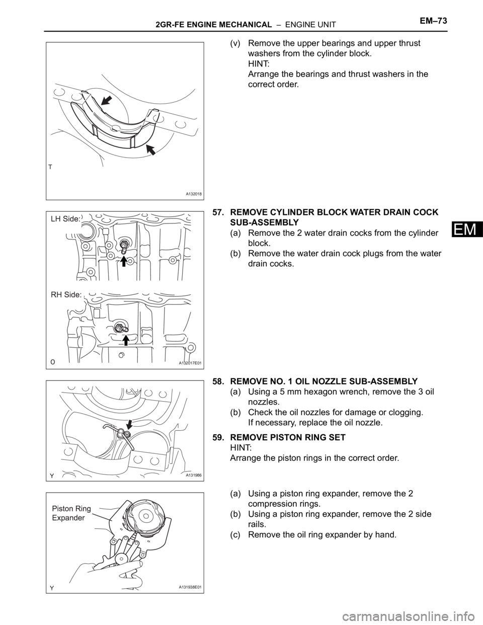
(v) Remove the upper bearings and upper thrust
washers from the cylinder block.
HINT:
Arrange the bearings and thrust washers in the
correct order.
57. REMOVE CYLINDER BLOCK WATER DRAIN COCK
SUB-ASSEMBLY
(a) Remove the 2 water drain cocks from the cylinder
block.
(b) Remove the water drain cock plugs from the water
drain cocks.
58. REMOVE NO. 1 OIL NOZZLE SUB-ASSEMBLY
(a) Using a 5 mm hexagon wrench, remove the 3 oil
nozzles.
(b) Check the oil nozzles for damage or clogging.
If necessary, replace the oil nozzle.
59. REMOVE PISTON RING SET
HINT:
Arrange the piston rings in the correct order.
(a) Using a piston ring expander, remove the 2
compression rings.
(b) Using a piston ring expander, remove the 2 side
rails.
(c) Remove the oil ring expander by hand.
A132018
A132017E01
A131986
A131938E01
Page 742 of 2000
2GR-FE ENGINE MECHANICAL – ENGINE UNITEM–105
EM
REASSEMBLY
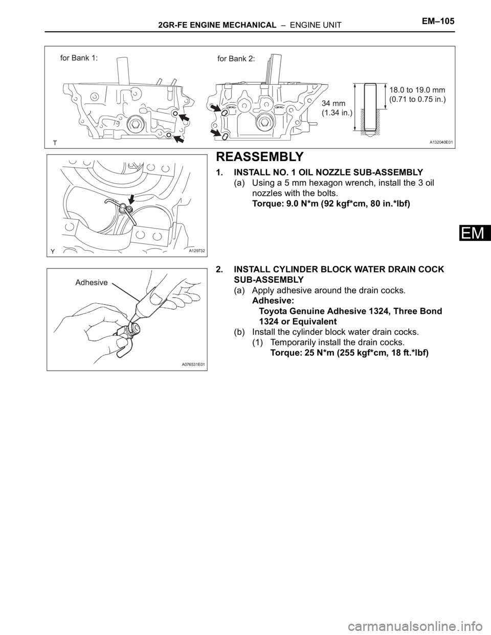
1. INSTALL NO. 1 OIL NOZZLE SUB-ASSEMBLY
(a) Using a 5 mm hexagon wrench, install the 3 oil
nozzles with the bolts.
Torque: 9.0 N*m (92 kgf*cm, 80 in.*lbf)
2. INSTALL CYLINDER BLOCK WATER DRAIN COCK
SUB-ASSEMBLY
(a) Apply adhesive around the drain cocks.
Adhesive:
Toyota Genuine Adhesive 1324, Three Bond
1324 or Equivalent
(b) Install the cylinder block water drain cocks.
(1) Temporarily install the drain cocks.
Torque: 25 N*m (255 kgf*cm, 18 ft.*lbf)
A132040E01
A129732
A076531E01
Page 743 of 2000
EM–1062GR-FE ENGINE MECHANICAL – ENGINE UNIT
EM
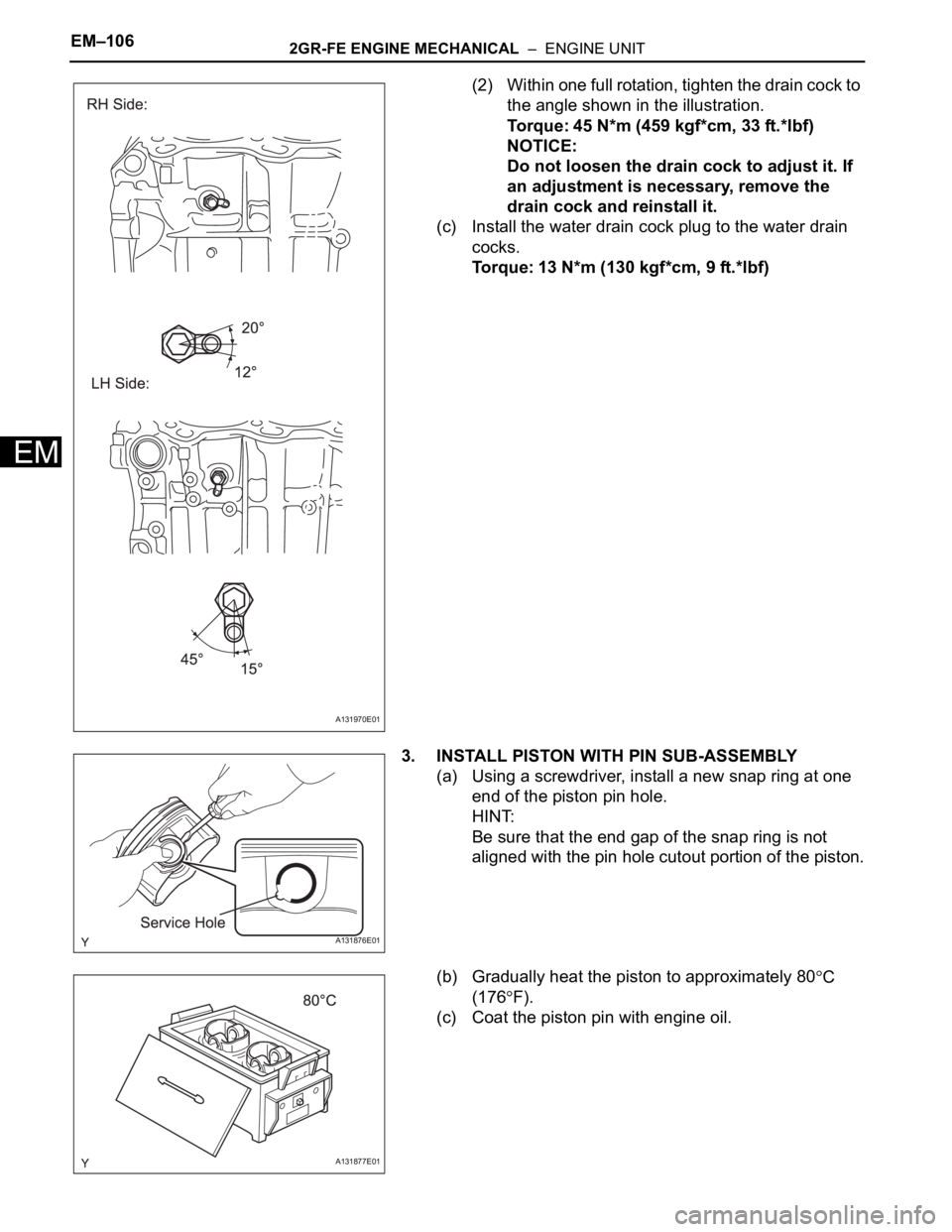
(2) Within one full rotation, tighten the drain cock to
the angle shown in the illustration.
Torque: 45 N*m (459 kgf*cm, 33 ft.*lbf)
NOTICE:
Do not loosen the drain cock to adjust it. If
an adjustment is necessary, remove the
drain cock and reinstall it.
(c) Install the water drain cock plug to the water drain
cocks.
Torque: 13 N*m (130 kgf*cm, 9 ft.*lbf)
3. INSTALL PISTON WITH PIN SUB-ASSEMBLY
(a) Using a screwdriver, install a new snap ring at one
end of the piston pin hole.
HINT:
Be sure that the end gap of the snap ring is not
aligned with the pin hole cutout portion of the piston.
(b) Gradually heat the piston to approximately 80
C
(176
F).
(c) Coat the piston pin with engine oil.
A131970E01
A131876E01
A131877E01
Page 883 of 2000
2GR-FE LUBRICATION – OIL PUMPLU–23
LU
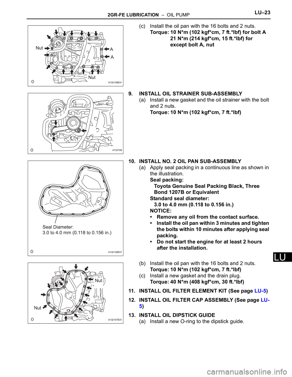
(c) Install the oil pan with the 16 bolts and 2 nuts.
Torque: 10 N*m (102 kgf*cm, 7 ft.*lbf) for bolt A
21 N*m (214 kgf*cm, 15 ft.*lbf) for
except bolt A, nut
9. INSTALL OIL STRAINER SUB-ASSEMBLY
(a) Install a new gasket and the oil strainer with the bolt
and 2 nuts.
Torque: 10 N*m (102 kgf*cm, 7 ft.*lbf)
10. INSTALL NO. 2 OIL PAN SUB-ASSEMBLY
(a) Apply seal packing in a continuous line as shown in
the illustration.
Seal packing:
Toyota Genuine Seal Packing Black, Three
Bond 1207B or Equivalent
Standard seal diameter:
3.0 to 4.0 mm (0.118 to 0.156 in.)
NOTICE:
• Remove any oil from the contact surface.
• Install the oil pan within 3 minutes and tighten
the bolts within 10 minutes after applying seal
packing.
• Do not start the engine for at least 2 hours
after the installation.
(b) Install the oil pan with the 16 bolts and 2 nuts.
Torque: 10 N*m (102 kgf*cm, 7 ft.*lbf)
(c) Install a new gasket and the drain plug.
Torque: 40 N*m (408 kgf*cm, 30 ft.*lbf)
11. INSTALL OIL FILTER ELEMENT KIT (See page LU-5)
12. INSTALL OIL FILTER CAP ASSEMBLY (See page LU-
5)
13. INSTALL OIL DIPSTICK GUIDE
(a) Install a new O-ring to the dipstick guide.
A132109E01
A132108
A132138E01
A132107E01
Page 976 of 2000
AX–144U140F AUTOMATIC TRANSAXLE – DIFFERENTIAL OIL SEAL
AX
REPLACEMENT
1. REPLACE TRANSAXLE HOUSING OIL SEAL LH
(a) Drain the automatic transaxle fluid.
(1) Remove the drain plug and gasket, and drain
AT F.
(2) Install a new gasket and drain plug.
Torque: 47 N*m (479 kgf*cm, 35 ft.*lbf)
(b) Remove the front drive shaft LH (see page DS-41).
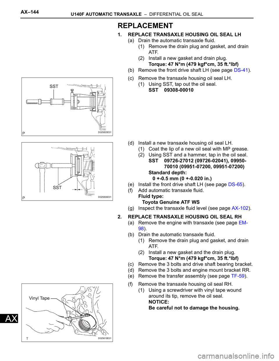
(c) Remove the transaxle housing oil seal LH.
(1) Using SST, tap out the oil seal.
SST 09308-00010
(d) Install a new transaxle housing oil seal LH.
(1) Coat the lip of a new oil seal with MP grease.
(2) Using SST and a hammer, tap in the oil seal.
SST 09726-27012 (09726-02041), 09950-
70010 (09951-07200, 09951-07200)
Standard depth:
0 +-0.5 mm (0 +-0.020 in.)
(e) Install the front drive shaft LH (see page DS-65).
(f) Add automatic transaxle fluid.
Fluid type:
Toyota Genuine ATF WS
(g) Inspect the transaxle fluid level (see page AX-102).
2. REPLACE TRANSAXLE HOUSING OIL SEAL RH
(a) Remove the engine with transaxle (see page EM-
98).
(b) Drain the automatic transaxle fluid.
(1) Remove the drain plug and gasket, and drain
AT F.
(2) Install a new gasket and the drain plug.
Torque: 47 N*m (479 kgf*cm, 35 ft.*lbf)
(c) Remove the 3 bolts and drive shaft bearing bracket.
(d) Remove the 3 bolts and engine mount bracket RR.
(e) Remove the transfer assembly (see page TF-59).
(f) Remove the transaxle housing oil seal RH.
(1) Using a screwdriver with vinyl tape wound
around its tip, remove the oil seal.
NOTICE:
Be careful not to damage the housing.
D025835E01
D025836E01
D025618E01
Page 1162 of 2000
AX–170U151F AUTOMATIC TRANSAXLE – DIFFERENTIAL OIL SEAL
AX
REPLACEMENT
1. REPLACE TRANSAXLE HOUSING OIL SEAL LH
(a) Drain the automatic transaxle fluid.
(1) Remove the drain plug and gasket, and drain
the ATF.
(2) Install a new gasket and drain plug.
Torque: 47 N*m (479 kgf*cm, 35 ft.*lbf)
(b) Remove the front drive shaft LH (see page DS-41).
(c) Remove the transaxle housing oil seal LH.
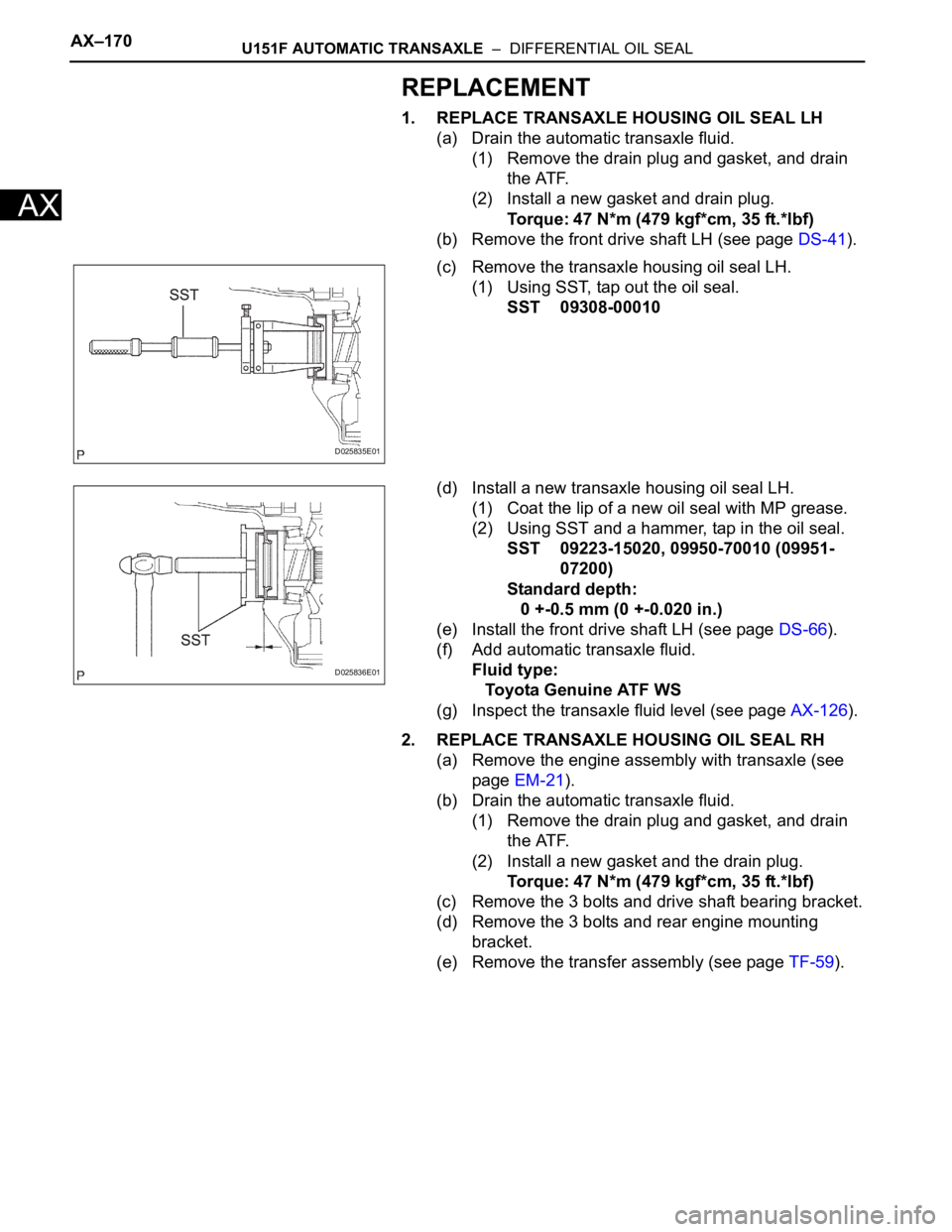
(1) Using SST, tap out the oil seal.
SST 09308-00010
(d) Install a new transaxle housing oil seal LH.
(1) Coat the lip of a new oil seal with MP grease.
(2) Using SST and a hammer, tap in the oil seal.
SST 09223-15020, 09950-70010 (09951-
07200)
Standard depth:
0 +-0.5 mm (0 +-0.020 in.)
(e) Install the front drive shaft LH (see page DS-66).
(f) Add automatic transaxle fluid.
Fluid type:
Toyota Genuine ATF WS
(g) Inspect the transaxle fluid level (see page AX-126).
2. REPLACE TRANSAXLE HOUSING OIL SEAL RH
(a) Remove the engine assembly with transaxle (see
page EM-21).
(b) Drain the automatic transaxle fluid.
(1) Remove the drain plug and gasket, and drain
the ATF.
(2) Install a new gasket and the drain plug.
Torque: 47 N*m (479 kgf*cm, 35 ft.*lbf)
(c) Remove the 3 bolts and drive shaft bearing bracket.
(d) Remove the 3 bolts and rear engine mounting
bracket.
(e) Remove the transfer assembly (see page TF-59).
D025835E01
D025836E01
Page 1422 of 2000
DF–18DIFFERENTIAL – REAR DIFFERENTIAL CARRIER ASSEMBLY
DF
REMOVAL
1. DRAIN DIFFERENTIAL OIL
2. REMOVE REAR WHEEL
3. REMOVE TAILPIPE ASSEMBLY
(a) Remove the tailpipe (see page EX-2).
4. REMOVE CENTER EXHAUST PIPE ASSEMBLY
(a) Remove the center pipe (see page EX-2).
5. REMOVE PROPELLER WITH CENTER BEARING
SHAFT ASSEMBLY (See page PR-3)
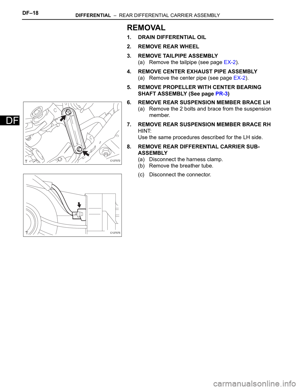
6. REMOVE REAR SUSPENSION MEMBER BRACE LH
(a) Remove the 2 bolts and brace from the suspension
member.
7. REMOVE REAR SUSPENSION MEMBER BRACE RH
HINT:
Use the same procedures described for the LH side.
8. REMOVE REAR DIFFERENTIAL CARRIER SUB-
ASSEMBLY
(a) Disconnect the harness clamp.
(b) Remove the breather tube.
(c) Disconnect the connector.
C127572
C127575
Page 1662 of 2000
AIR CONDITIONING – COMPRESSOR AND PULLEY (for 2AZ-FE)AC–217
AC
INSTALLATION
1. ADJUST ADJUST COMPRESSOR OIL
(a) When replacing the compressor and magnetic
clutch with a new one, gradually discharge the
refrigerant gas from the service valve, and drain the
following amount of oil from the new compressor
and magnetic clutch before installation.
Standard:
(Oil capacity inside the new compressor and
magnetic clutch: 130 + 15 cc (4.6 + 0.51 fl.oz.) )
-(Remaining oil amount in the removed
compressor and magnetic clutch) = (Oil
amount to be removed from the new
compressor when replacing)
NOTICE:
• When checking the compressor oil level,
observe the precautions on the cooler
removal/installation.
• If a new compressor and magnetic clutch is
installed without removing some oil
remaining in the pipes of the vehicle, the oil
amount will be too large. This prevents heat
exchange in the refrigerant cycle and causes
refrigerant failure.
• If the volume of oil remaining in the removed
compressor and magnetic clutch is too small,
check for oil leakage.
• Be sure to use ND-OIL 8 or equivalent for
compressor oil.
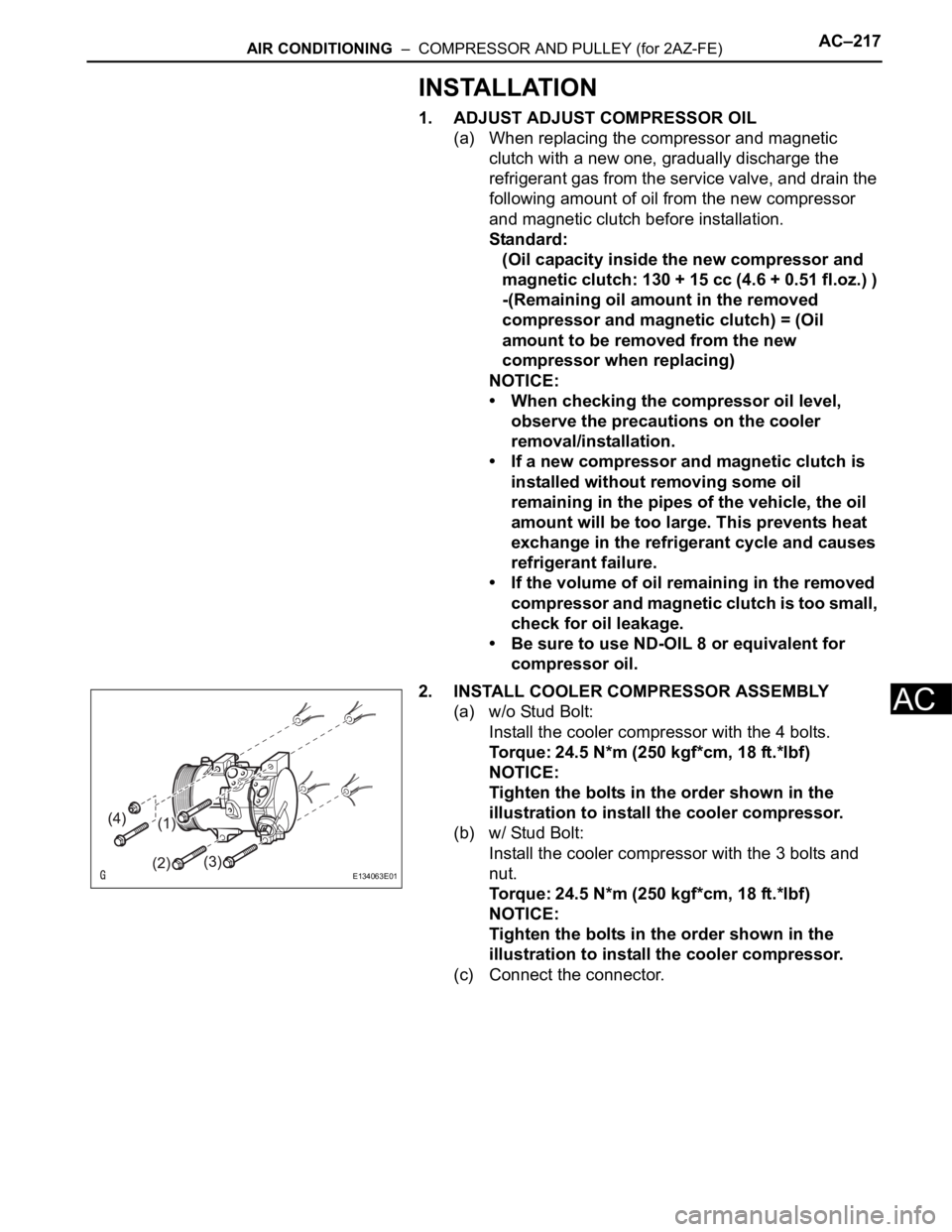
2. INSTALL COOLER COMPRESSOR ASSEMBLY
(a) w/o Stud Bolt:
Install the cooler compressor with the 4 bolts.
Torque: 24.5 N*m (250 kgf*cm, 18 ft.*lbf)
NOTICE:
Tighten the bolts in the order shown in the
illustration to install the cooler compressor.
(b) w/ Stud Bolt:
Install the cooler compressor with the 3 bolts and
nut.
Torque: 24.5 N*m (250 kgf*cm, 18 ft.*lbf)
NOTICE:
Tighten the bolts in the order shown in the
illustration to install the cooler compressor.
(c) Connect the connector.
E134063E01