Install TOYOTA RAV4 2006 Service Owner's Guide
[x] Cancel search | Manufacturer: TOYOTA, Model Year: 2006, Model line: RAV4, Model: TOYOTA RAV4 2006Pages: 2000, PDF Size: 45.84 MB
Page 366 of 2000
AX–290U151F AUTOMATIC TRANSAXLE – DIFFERENTIAL CASE
AX
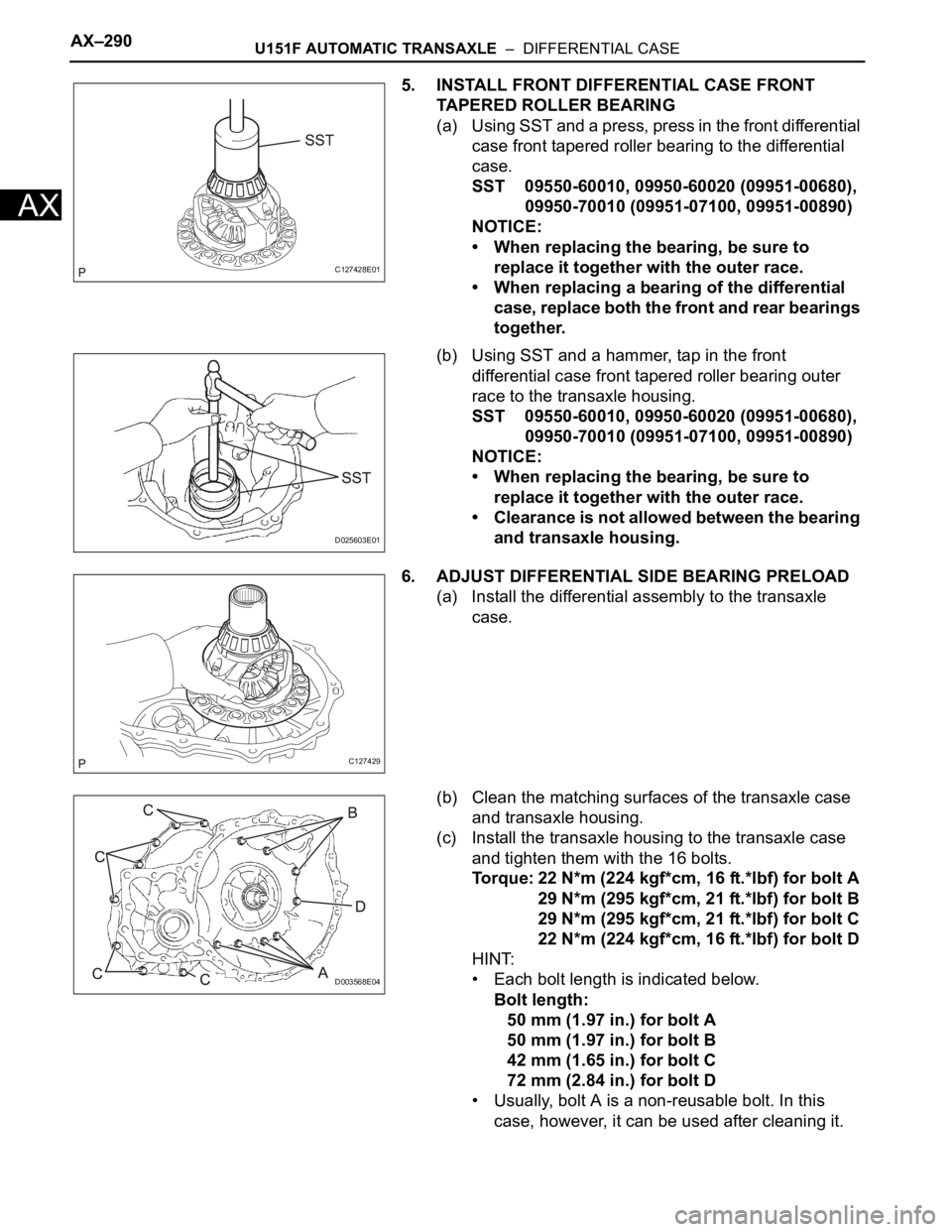
5. INSTALL FRONT DIFFERENTIAL CASE FRONT
TAPERED ROLLER BEARING
(a) U si ng SST and a pres s, pr es s in the f ron t di fferent ial
case front tapered roller bearing to the differential
case.
SST 09550-60010, 09950-60020 (09951-00680),
09950-70010 (09951-07100, 09951-00890)
NOTICE:
• When replacing the bearing, be sure to
replace it together with the outer race.
• When replacing a bearing of the differential
case, replace both the front and rear bearings
together.
(b) Using SST and a hammer, tap in the front
differential case front tapered roller bearing outer
race to the transaxle housing.
SST 09550-60010, 09950-60020 (09951-00680),
09950-70010 (09951-07100, 09951-00890)
NOTICE:
• When replacing the bearing, be sure to
replace it together with the outer race.
• Clearance is not allowed between the bearing
and transaxle housing.
6. ADJUST DIFFERENTIAL SIDE BEARING PRELOAD
(a) Install the differential assembly to the transaxle
case.
(b) Clean the matching surfaces of the transaxle case
and transaxle housing.
(c) Install the transaxle housing to the transaxle case
and tighten them with the 16 bolts.
Torque: 22 N*m (224 kgf*cm, 16 ft.*lbf) for bolt A
29 N*m (295 kgf*cm, 21 ft.*lbf) for bolt B
29 N*m (295 kgf*cm, 21 ft.*lbf) for bolt C
22 N*m (224 kgf*cm, 16 ft.*lbf) for bolt D
HINT:
• Each bolt length is indicated below.
Bolt length:
50 mm (1.97 in.) for bolt A
50 mm (1.97 in.) for bolt B
42 mm (1.65 in.) for bolt C
72 mm (2.84 in.) for bolt D
• Usually, bolt A is a non-reusable bolt. In this
case, however, it can be used after cleaning it.
C127428E01
D025603E01
C127429
D003568E04
Page 368 of 2000
AX–292U151F AUTOMATIC TRANSAXLE – DIFFERENTIAL CASE
AX
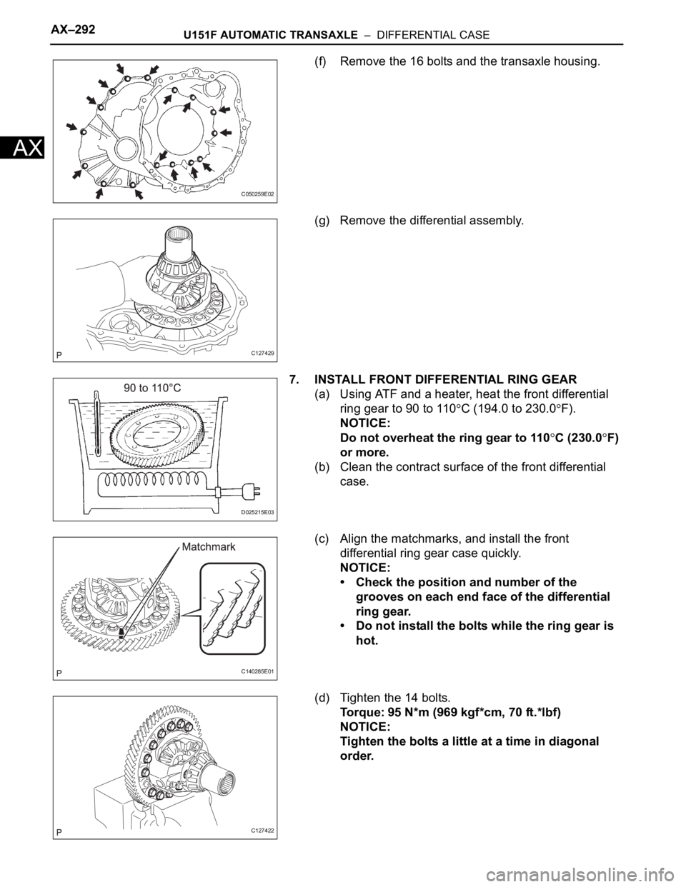
(f) Remove the 16 bolts and the transaxle housing.
(g) Remove the differential assembly.
7. INSTALL FRONT DIFFERENTIAL RING GEAR
(a) Using ATF and a heater, heat the front differential
ring gear to 90 to 110
C (194.0 to 230.0F).
NOTICE:
Do not overheat the ring gear to 110
C (230.0F)
or more.
(b) Clean the contract surface of the front differential
case.
(c) Align the matchmarks, and install the front
differential ring gear case quickly.
NOTICE:
• Check the position and number of the
grooves on each end face of the differential
ring gear.
• Do not install the bolts while the ring gear is
hot.
(d) Tighten the 14 bolts.
Torque: 95 N*m (969 kgf*cm, 70 ft.*lbf)
NOTICE:
Tighten the bolts a little at a time in diagonal
order.
C050259E02
C127429
D025215E03
C140285E01
C127422
Page 369 of 2000

U151F AUTOMATIC TRANSAXLE – DIFFERENTIAL CASEAX–293
AX
8. INSTALL DIFFERENTIAL SIDE BEARING RETAINER
OIL SEAL
(a) Coat the lip of a new oil seal with a small amount of
MP grease.
(b) Using SST and a hammer, tap in the oil seal.
SST 09223-15020, 09950-70010 (09951-07100)
9. REMOVE TRANSAXLE HOUSING OIL SEAL
(a) Coat the lip of a new oil seal with a small amount of
MP grease.
(b) Using SST and a hammer, tap in the oil seal.
SST 09710-30050, 09950-70010 (09951-07100)
C083738E02
D025606E01
Page 376 of 2000
AX–248U241E AUTOMATIC TRANSAXLE – UNDERDRIVE CLUTCH
AX
INSPECTION
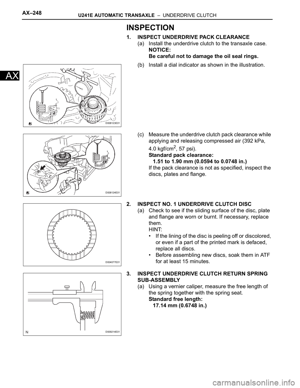
1. INSPECT UNDERDRIVE PACK CLEARANCE
(a) Install the underdrive clutch to the transaxle case.
NOTICE:
Be careful not to damage the oil seal rings.
(b) Install a dial indicator as shown in the illustration.
(c) Measure the underdrive clutch pack clearance while
applying and releasing compressed air (392 kPa,
4.0 kgf/cm
2, 57 psi).
Standard pack clearance:
1.51 to 1.90 mm (0.0594 to 0.0748 in.)
If the pack clearance is not as specified, inspect the
discs, plates and flange.
2. INSPECT NO. 1 UNDERDRIVE CLUTCH DISC
(a) Check to see if the sliding surface of the disc, plate
and flange are worn or burnt. If necessary, replace
them.
HINT:
• If the lining of the disc is peeling off or discolored,
or even if a part of the printed mark is defaced,
replace all discs.
• Before assembling new discs, soak them in ATF
for at least 15 minutes.
3. INSPECT UNDERDRIVE CLUTCH RETURN SPRING
SUB-ASSEMBLY
(a) Using a vernier caliper, measure the free length of
the spring together with the spring seat.
Standard free length:
17.14 mm (0.6748 in.)
D008123E01
D008124E01
D004077E01
D009214E01
Page 377 of 2000

U241E AUTOMATIC TRANSAXLE – UNDERDRIVE CLUTCHAX–249
AX
4. INSPECT UNDERDRIVE CLUTCH DRUM SUB-
ASSEMBLY
(a) Using a caliper gauge, measure the inside diameter
of the underdrive clutch drum bush.
Standard drum bush:
32.56 to 32.58 mm (1.2818 to 1.2826 in.)
Maximum drum bush:
32.63 mm (1.2846 in.)
If the inside diameter is greater than the maximum,
replace the underdrive clutch drum sub-assembly.
REASSEMBLY
1. INSTALL UNDERDRIVE CLUTCH DRUM O-RING
(a) Coat a new O-ring with ATF and install it to the
underdrive clutch drum.
2. INSTALL UNDERDRIVE CLUTCH PISTON SET
(a) Coat the underdrive clutch piston with ATF, and
install it to the underdrive clutch piston drum.
NOTICE:
Be careful not to damage the O-ring.
(b) Install the piston return spring and clutch balancer to
the underdrive clutch drum.
NOTICE:
Be careful not to damage the lip seal of the
clutch balancer.
(c) Place SST on the clutch balancer and compress the
piston return spring with a press.
SST 09350-32014 (09351-32070)
(d) Using a snap ring expander, install the snap ring to
underdrive clutch drum.
NOTICE:
• Be sure the end gap of the snap ring is not
aligned with the clutch balancer's claw.
• Stop the press when the spring sheet is
lowered to the place 1 to 2 mm (0.039 to 0.078
in.) from the sap ring groove.
D008129E02
D004078E01
D003860E01
D003704E01
D003703E02
Page 378 of 2000
AX–250U241E AUTOMATIC TRANSAXLE – UNDERDRIVE CLUTCH
AX
• This prevents the spring sheet from being
deformed.
• Do not expand the snap ring excessively.
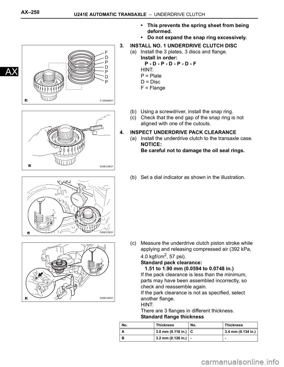
3. INSTALL NO. 1 UNDERDRIVE CLUTCH DISC
(a) Install the 3 plates, 3 discs and flange.
Install in order:
P - D - P - D - P - D - F
HINT:
P = Plate
D = Disc
F = Flange
(b) Using a screwdriver, install the snap ring.
(c) Check that the end gap of the snap ring is not
aligned with one of the cutouts.
4. INSPECT UNDERDRIVE PACK CLEARANCE
(a) Install the underdrive clutch to the transaxle case.
NOTICE:
Be careful not to damage the oil seal rings.
(b) Set a dial indicator as shown in the illustration.
(c) Measure the underdrive clutch piston stroke while
applying and releasing compressed air (392 kPa,
4.0 kgf/cm
2, 57 psi).
Standard pack clearance:
1.51 to 1.90 mm (0.0594 to 0.0748 in.)
If the pack clearance is less than the minimum,
parts may have been assembled incorrectly, so
check and reassemble again.
If the park clearance is not as specified, select
another flange.
HINT:
There are 3 flanges in different thickness.
Standard flange thickness
C129394E01
D008125E01
D008123E01
D008124E01
No. Thickness No. Thickness
A 3.0 mm (0.118 in.) C 3.4 mm (0.134 in.)
B 3.2 mm (0.126 in.) - -
Page 396 of 2000
PROPELLER SHAFT – PROPELLER SHAFT ASSEMBLYPR–5
PR
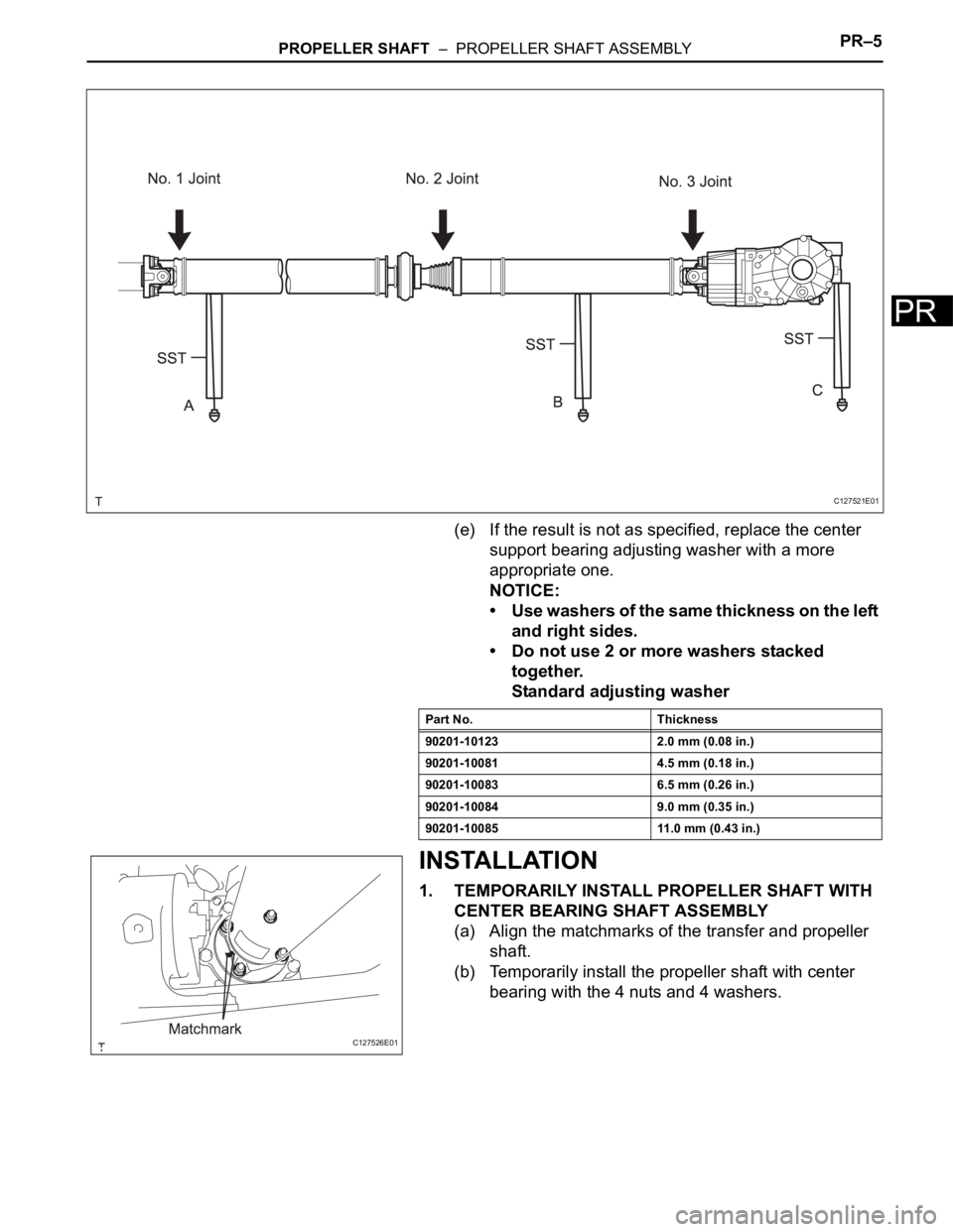
(e) If the result is not as specified, replace the center
support bearing adjusting washer with a more
appropriate one.
NOTICE:
• Use washers of the same thickness on the left
and right sides.
• Do not use 2 or more washers stacked
together.
Standard adjusting washer
INSTALLATION
1. TEMPORARILY INSTALL PROPELLER SHAFT WITH
CENTER BEARING SHAFT ASSEMBLY
(a) Align the matchmarks of the transfer and propeller
shaft.
(b) Temporarily install the propeller shaft with center
bearing with the 4 nuts and 4 washers.
C127521E01
Part No. Thickness
90201-10123 2.0 mm (0.08 in.)
90201-10081 4.5 mm (0.18 in.)
90201-10083 6.5 mm (0.26 in.)
90201-10084 9.0 mm (0.35 in.)
90201-10085 11.0 mm (0.43 in.)
C127526E01
Page 397 of 2000
PR–6PROPELLER SHAFT – PROPELLER SHAFT ASSEMBLY
PR
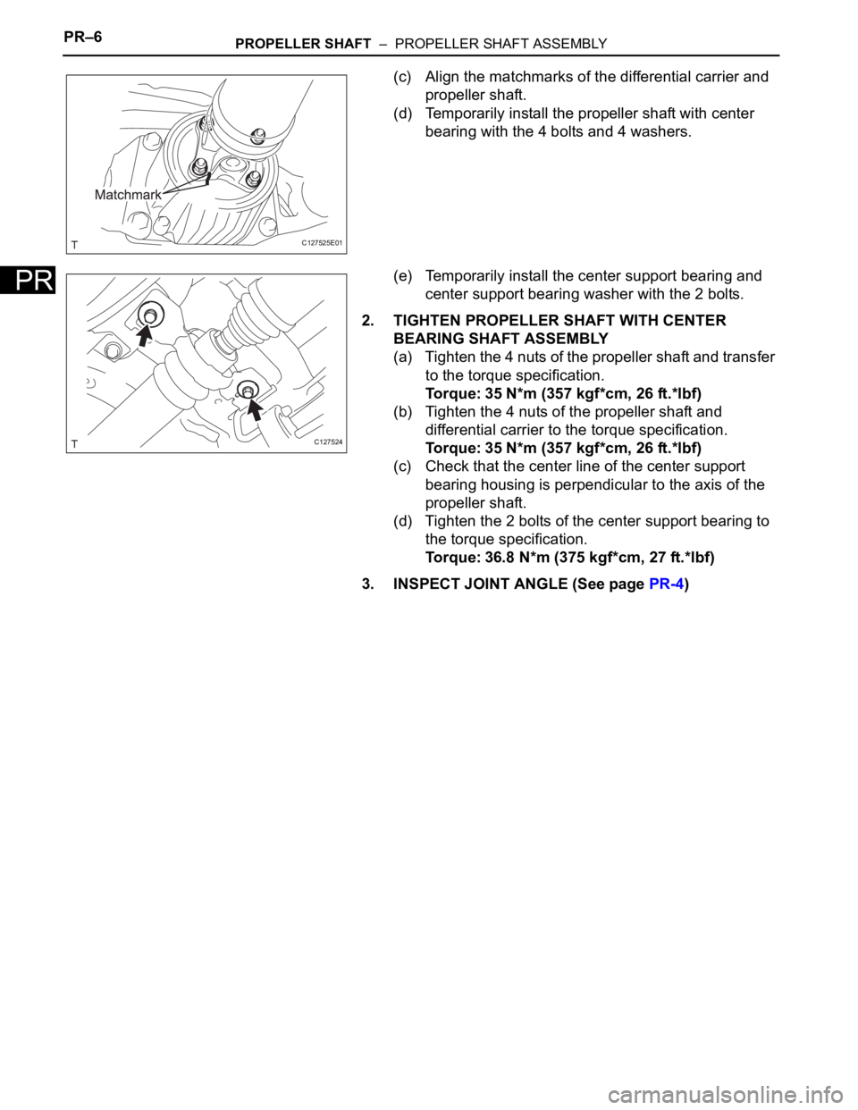
(c) Align the matchmarks of the differential carrier and
propeller shaft.
(d) Temporarily install the propeller shaft with center
bearing with the 4 bolts and 4 washers.
(e) Temporarily install the center support bearing and
center support bearing washer with the 2 bolts.
2. TIGHTEN PROPELLER SHAFT WITH CENTER
BEARING SHAFT ASSEMBLY
(a) Tighten the 4 nuts of the propeller shaft and transfer
to the torque specification.
Torque: 35 N*m (357 kgf*cm, 26 ft.*lbf)
(b) Tighten the 4 nuts of the propeller shaft and
differential carrier to the torque specification.
Torque: 35 N*m (357 kgf*cm, 26 ft.*lbf)
(c) Check that the center line of the center support
bearing housing is perpendicular to the axis of the
propeller shaft.
(d) Tighten the 2 bolts of the center support bearing to
the torque specification.
Torque: 36.8 N*m (375 kgf*cm, 27 ft.*lbf)
3. INSPECT JOINT ANGLE (See page PR-4)
C127525E01
C127524
Page 401 of 2000
DIFFERENTIAL – REAR DIFFERENTIAL SIDE GEAR SHAFT OIL SEALDF–7
DF
REMOVAL
1. DRAIN DIFFERENTIAL OIL (See page DF-10)
2. REMOVE TAILPIPE ASSEMBLY
(a) Remove the tailpipe (see page EX-2).
3. REMOVE CENTER EXHAUST ASSEMBLY
(a) Remove the center pipe (see page EX-2).
4. REMOVE PROPELLER WITH CENTER BEARING
SHAFT ASSEMBLY (See page PR-3)
5. REMOVE REAR DIFFERENTIAL CARRIER SUB-
ASSEMBLY (See page DF-18)
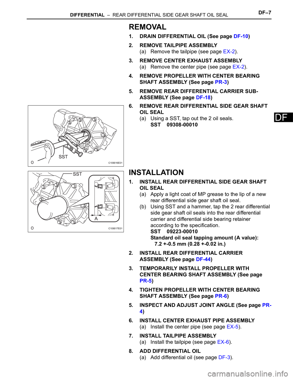
6. REMOVE REAR DIFFERENTIAL SIDE GEAR SHAFT
OIL SEAL
(a) Using a SST, tap out the 2 oil seals.
SST 09308-00010
INSTALLATION
1. INSTALL REAR DIFFERENTIAL SIDE GEAR SHAFT
OIL SEAL
(a) Apply a light coat of MP grease to the lip of a new
rear differential side gear shaft oil seal.
(b) Using SST and a hammer, tap the 2 rear differential
side gear shaft oil seals into the rear differential
carrier and differential side bearing retainer
according to the specification.
SST 09223-00010
Standard oil seal tapping amount (A value):
7.2 +-0.5 mm (0.28 +-0.02 in.)
2. INSTALL REAR DIFFERENTIAL CARRIER
ASSEMBLY (See page DF-44)
3. TEMPORARILY INSTALL PROPELLER WITH
CENTER BEARING SHAFT ASSEMBLY (See page
PR-5)
4. TIGHTEN PROPELLER WITH CENTER BEARING
SHAFT ASSEMBLY (See page PR-6)
5. INSPECT AND ADJUST JOINT ANGLE (See page PR-
4)
6. INSTALL CENTER EXHAUST PIPE ASSEMBLY
(a) Install the center pipe (see page EX-5).
7. INSTALL TAILPIPE ASSEMBLY
(a) Install the tailpipe (see page EX-6).
8. ADD DIFFERENTIAL OIL
(a) Add differential oil (see page DF-3).
C109016E01
C109017E01
Page 406 of 2000
SP–10SUSPENSION – FRONT SHOCK ABSORBER WITH COIL SPRING
SP
DISASSEMBLY
HINT:
• Use the same procedures for the RH side and LH side.
• The procedures listed below are for the LH side.
1. REMOVE FRONT SUSPENSION SUPPORT PLATE LH
(a) Remove the plate from the shock absorber.
2. REMOVE FRONT SUSPENSION SUPPORT DUST
COVER LH
(a) Using a screwdriver, remove the dust cover from the
suspension support.
HINT:
Tape the screwdriver tip before use.
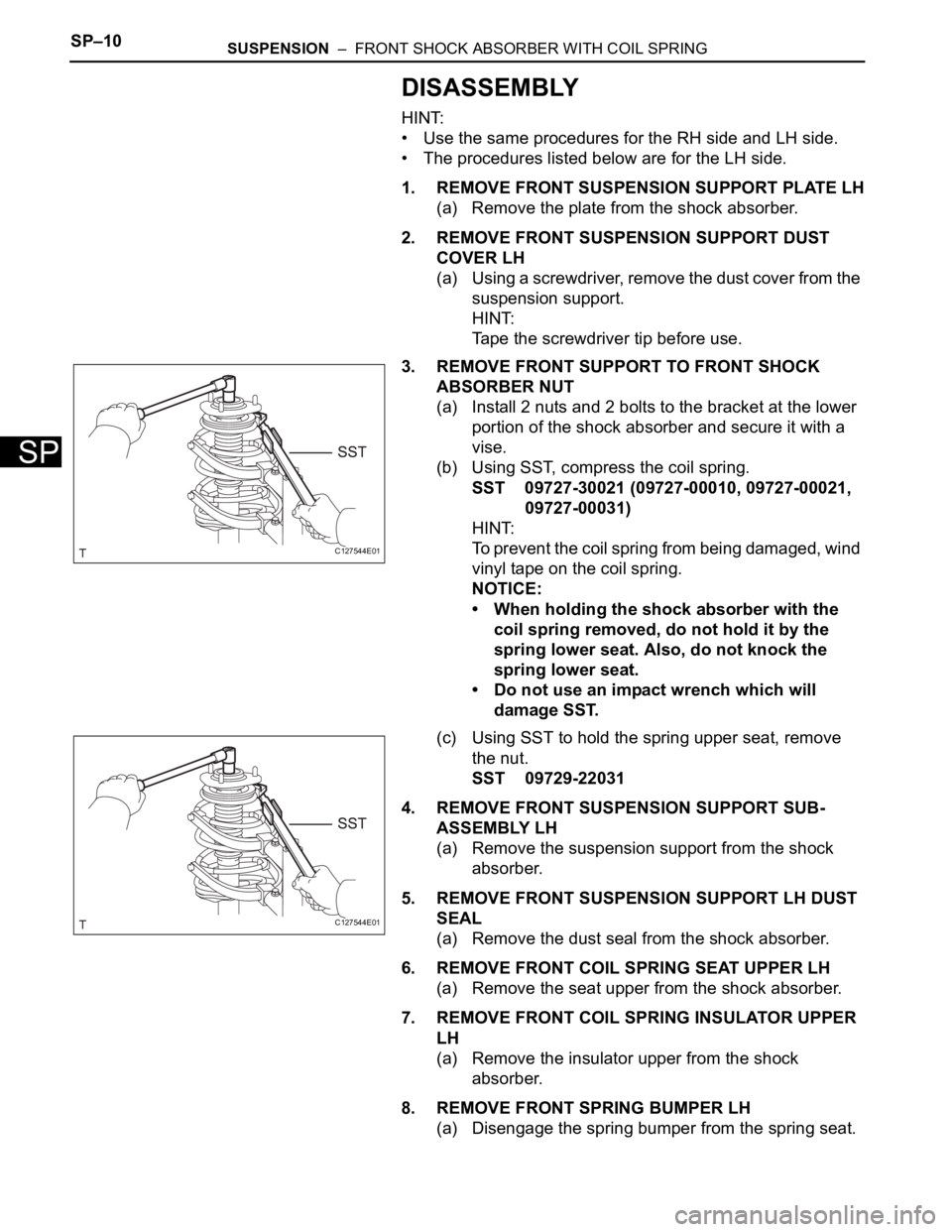
3. REMOVE FRONT SUPPORT TO FRONT SHOCK
ABSORBER NUT
(a) Install 2 nuts and 2 bolts to the bracket at the lower
portion of the shock absorber and secure it with a
vise.
(b) Using SST, compress the coil spring.
SST 09727-30021 (09727-00010, 09727-00021,
09727-00031)
HINT:
To prevent the coil spring from being damaged, wind
vinyl tape on the coil spring.
NOTICE:
• When holding the shock absorber with the
coil spring removed, do not hold it by the
spring lower seat. Also, do not knock the
spring lower seat.
• Do not use an impact wrench which will
damage SST.
(c) Using SST to hold the spring upper seat, remove
the nut.
SST 09729-22031
4. REMOVE FRONT SUSPENSION SUPPORT SUB-
ASSEMBLY LH
(a) Remove the suspension support from the shock
absorber.
5. REMOVE FRONT SUSPENSION SUPPORT LH DUST
SEAL
(a) Remove the dust seal from the shock absorber.
6. REMOVE FRONT COIL SPRING SEAT UPPER LH
(a) Remove the seat upper from the shock absorber.
7. REMOVE FRONT COIL SPRING INSULATOR UPPER
LH
(a) Remove the insulator upper from the shock
absorber.
8. REMOVE FRONT SPRING BUMPER LH
(a) Disengage the spring bumper from the spring seat.
C127544E01
C127544E01