air suspension TOYOTA RAV4 2006 Service Repair Manual
[x] Cancel search | Manufacturer: TOYOTA, Model Year: 2006, Model line: RAV4, Model: TOYOTA RAV4 2006Pages: 2000, PDF Size: 45.84 MB
Page 380 of 2000
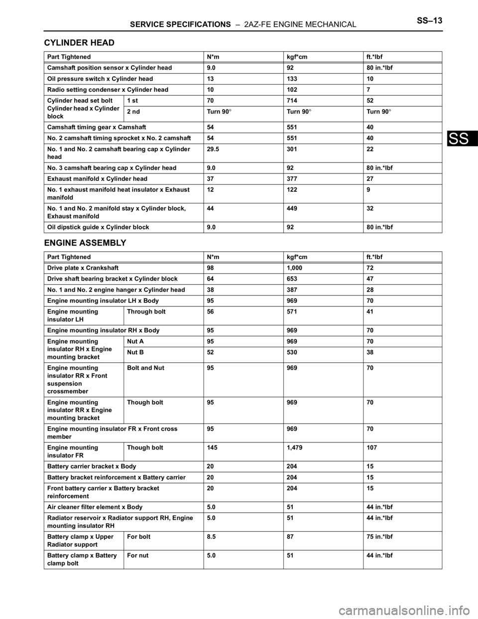
SERVICE SPECIFICATIONS – 2AZ-FE ENGINE MECHANICALSS–13
SS
CYLINDER HEAD
ENGINE ASSEMBLY
Part Tightened N*m kgf*cm ft.*lbf
Camshaft position sensor x Cylinder head 9.0 92 80 in.*lbf
Oil pressure switch x Cylinder head 13 133 10
Radio setting condenser x Cylinder head 10 102 7
Cylinder head set bolt
Cylinder head x Cylinder
block1 st 70 714 52
2 nd Turn 90
Tu r n 9 0Tu r n 9 0
Camshaft timing gear x Camshaft 54 551 40
No. 2 camshaft timing sprocket x No. 2 camshaft 54 551 40
No. 1 and No. 2 camshaft bearing cap x Cylinder
head29.5 301 22
No. 3 camshaft bearing cap x Cylinder head 9.0 92 80 in.*lbf
Exhaust manifold x Cylinder head 37 377 27
No. 1 exhaust manifold heat insulator x Exhaust
manifold12 122 9
No. 1 and No. 2 manifold stay x Cylinder block,
Exhaust manifold44 449 32
Oil dipstick guide x Cylinder block 9.0 92 80 in.*lbf
Part Tightened N*m kgf*cm ft.*lbf
Drive plate x Crankshaft 98 1,000 72
Drive shaft bearing bracket x Cylinder block 64 653 47
No. 1 and No. 2 engine hanger x Cylinder head 38 387 28
Engine mounting insulator LH x Body 95 969 70
Engine mounting
insulator LHThrough bolt 56 571 41
Engine mounting insulator RH x Body 95 969 70
Engine mounting
insulator RH x Engine
mounting bracketNut A 95 969 70
Nut B 52 530 38
Engine mounting
insulator RR x Front
suspension
crossmemberBolt and Nut 95 969 70
Engine mounting
insulator RR x Engine
mounting bracketThough bolt 95 969 70
Engine mounting insulator FR x Front cross
member95 969 70
Engine mounting
insulator FRThough bolt 145 1,479 107
Battery carrier bracket x Body 20 204 15
Battery bracket reinforcement x Battery carrier 20 204 15
Front battery carrier x Battery bracket
reinforcement20 204 15
Air cleaner filter element x Body 5.0 51 44 in.*lbf
Radiator reservoir x Radiator support RH, Engine
mounting insulator RH5.0 51 44 in.*lbf
Battery clamp x Upper
Radiator supportFor bolt 8.5 87 75 in.*lbf
Battery clamp x Battery
clamp boltFor nut 5.0 51 44 in.*lbf
Page 383 of 2000
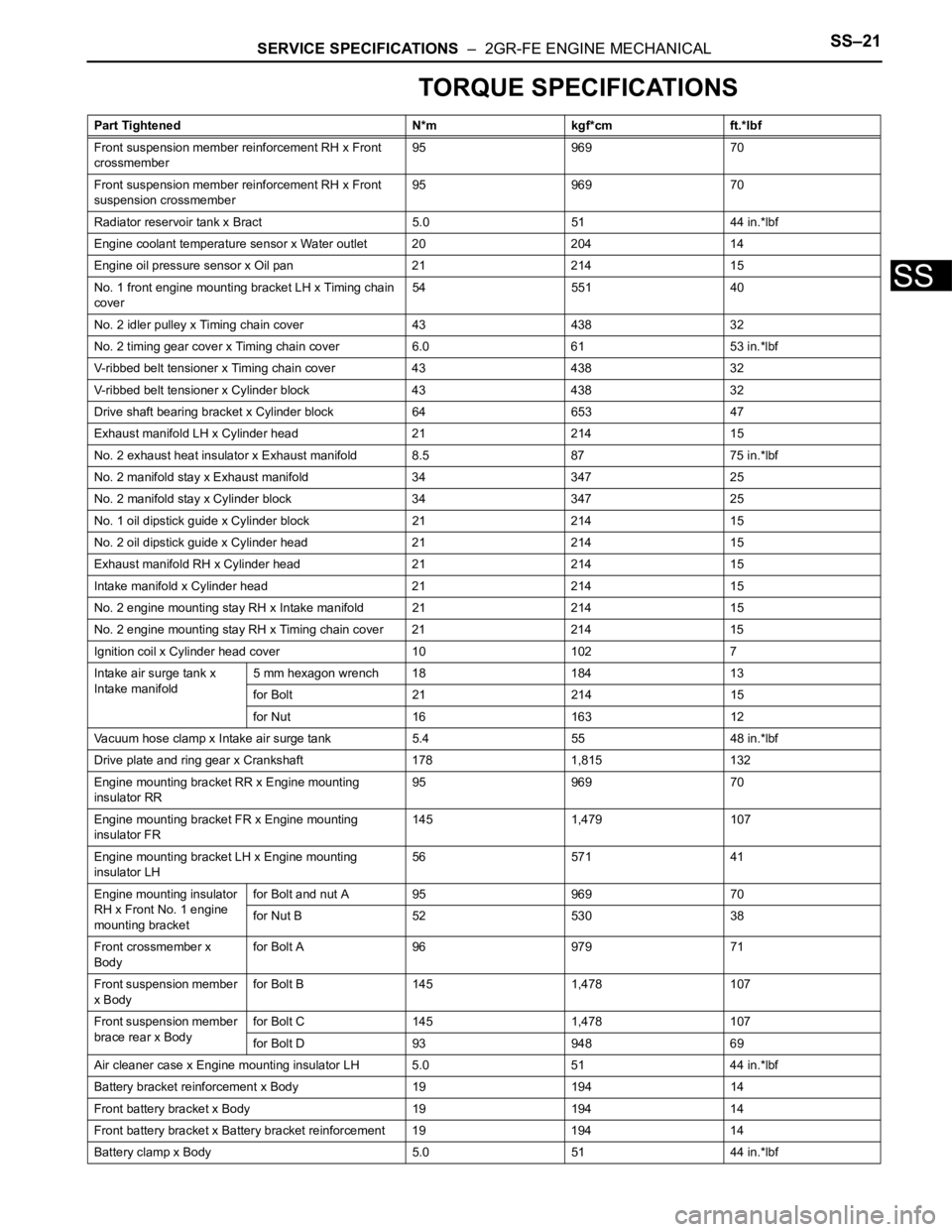
SERVICE SPECIFICATIONS – 2GR-FE ENGINE MECHANICALSS–21
SS
TORQUE SPECIFICATIONS
Part Tightened N*m kgf*cm ft.*lbf
Front suspension member reinforcement RH x Front
crossmember95 969 70
Front suspension member reinforcement RH x Front
suspension crossmember95 969 70
Radiator reservoir tank x Bract 5.0 51 44 in.*lbf
Engine coolant temperature sensor x Water outlet 20 204 14
Engine oil pressure sensor x Oil pan 21 214 15
No. 1 front engine mounting bracket LH x Timing chain
cover54 551 40
No. 2 idler pulley x Timing chain cover 43 438 32
No. 2 timing gear cover x Timing chain cover 6.0 61 53 in.*lbf
V-ribbed belt tensioner x Timing chain cover 43 438 32
V-ribbed belt tensioner x Cylinder block 43 438 32
Drive shaft bearing bracket x Cylinder block 64 653 47
Exhaust manifold LH x Cylinder head 21 214 15
No. 2 exhaust heat insulator x Exhaust manifold 8.5 87 75 in.*lbf
No. 2 manifold stay x Exhaust manifold 34 347 25
No. 2 manifold stay x Cylinder block 34 347 25
No. 1 oil dipstick guide x Cylinder block 21 214 15
No. 2 oil dipstick guide x Cylinder head 21 214 15
Exhaust manifold RH x Cylinder head 21 214 15
Intake manifold x Cylinder head 21 214 15
No. 2 engine mounting stay RH x Intake manifold 21 214 15
No. 2 engine mounting stay RH x Timing chain cover 21 214 15
Ignition coil x Cylinder head cover 10 102 7
Intake air surge tank x
Intake manifold5 mm hexagon wrench 18 184 13
for Bolt 21 214 15
for Nut 16 163 12
Vacuum hose clamp x Intake air surge tank 5.4 55 48 in.*lbf
Drive plate and ring gear x Crankshaft 178 1,815 132
Engine mounting bracket RR x Engine mounting
insulator RR95 969 70
Engine mounting bracket FR x Engine mounting
insulator FR145 1,479 107
Engine mounting bracket LH x Engine mounting
insulator LH56 571 41
Engine mounting insulator
RH x Front No. 1 engine
mounting bracketfor Bolt and nut A 95 969 70
for Nut B 52 530 38
Front crossmember x
Bodyfor Bolt A 96 979 71
Front suspension member
x Bodyfor Bolt B 145 1,478 107
Front suspension member
brace rear x Bodyfor Bolt C 145 1,478 107
for Bolt D 93 948 69
Air cleaner case x Engine mounting insulator LH 5.0 51 44 in.*lbf
Battery bracket reinforcement x Body 19 194 14
Front battery bracket x Body 19 194 14
Front battery bracket x Battery bracket reinforcement 19 194 14
Battery clamp x Body 5.0 51 44 in.*lbf
Page 404 of 2000
AXLE – FRONT AXLE HUBAH–7
AH
REMOVAL
(2005/11-2006/01)
HINT:
• Use the same procedures for the RH side and LH side.
• The procedures listed below are for the LH side.
1. REMOVE FRONT WHEEL
2. DRAIN AUTOMATIC TRANSAXLE FLUID
(a) Drain the automatic transaxle fluid for U140F (see
page AX-147).
(b) Drain the automatic transaxle fluid for U241E (see
page AX-146).
3. DISCONNECT CABLE FROM NEGATIVE BATTERY
TERMINAL
CAUTION:
Wait at least 90 seconds after disconnecting the
cable from the negative (-) battery terminal to
prevent airbag and seat belt pretensioner activation.
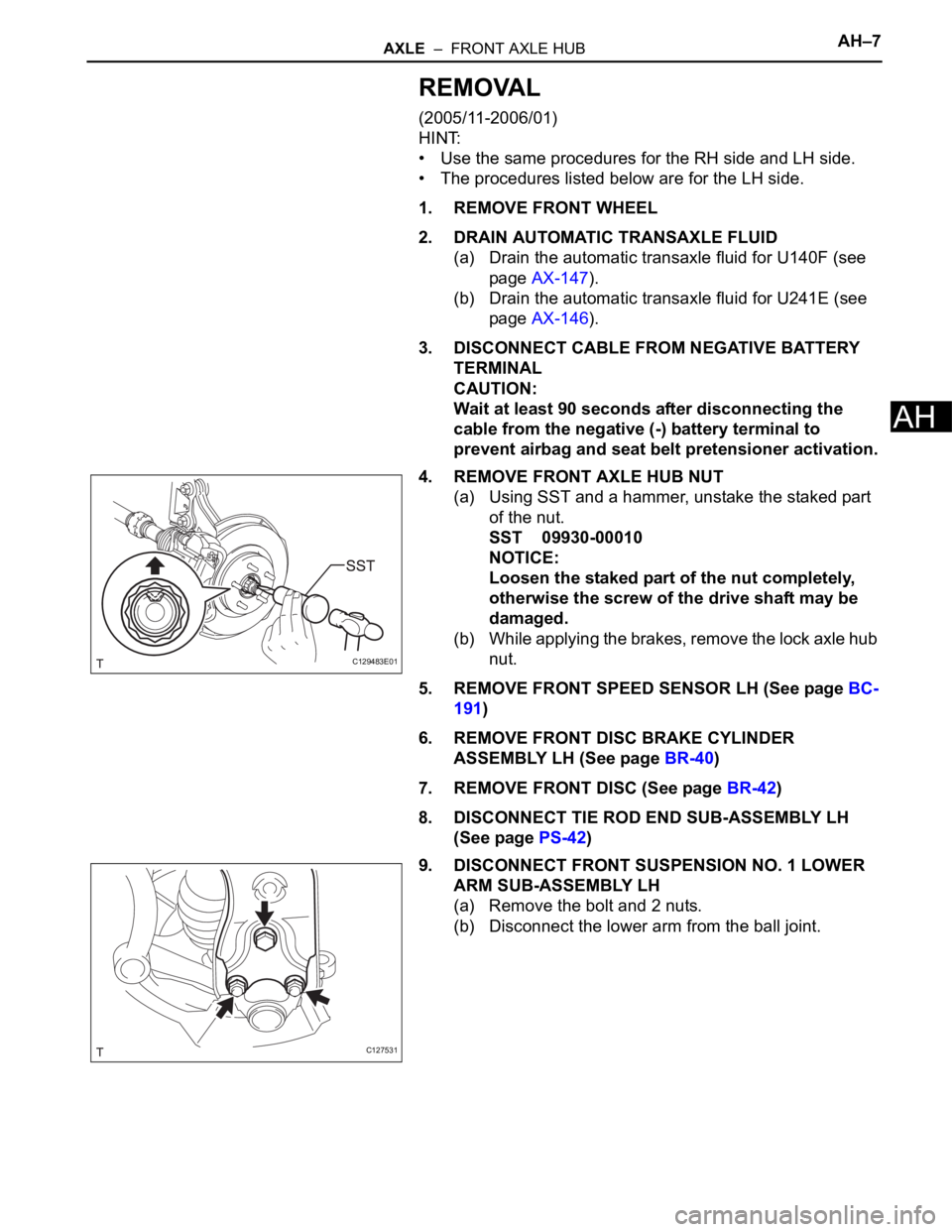
4. REMOVE FRONT AXLE HUB NUT
(a) Using SST and a hammer, unstake the staked part
of the nut.
SST 09930-00010
NOTICE:
Loosen the staked part of the nut completely,
otherwise the screw of the drive shaft may be
damaged.
(b) While applying the brakes, remove the lock axle hub
nut.
5. REMOVE FRONT SPEED SENSOR LH (See page BC-
191)
6. REMOVE FRONT DISC BRAKE CYLINDER
ASSEMBLY LH (See page BR-40)
7. REMOVE FRONT DISC (See page BR-42)
8. DISCONNECT TIE ROD END SUB-ASSEMBLY LH
(See page PS-42)
9. DISCONNECT FRONT SUSPENSION NO. 1 LOWER
ARM SUB-ASSEMBLY LH
(a) Remove the bolt and 2 nuts.
(b) Disconnect the lower arm from the ball joint.
C129483E01
C127531
Page 579 of 2000
EM–222AZ-FE ENGINE MECHANICAL – TIMING CHAIN
EM
REMOVAL
1. DISCONNECT CABLE FROM NEGATIVE BATTERY
TERMINAL
CAUTION:
Wait at least 90 seconds after disconnecting the
cable from the negative (-) battery terminal to
prevent airbag and seat belt pretensioner activation.
2. REMOVE RADIATOR SUPPORT OPENING COVER
3. REMOVE FRONT WHEEL RH
4. REMOVE NO. 1 ENGINE UNDER COVER
5. REMOVE FRONT FENDER APRON RH
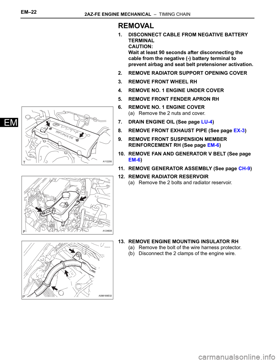
6. REMOVE NO. 1 ENGINE COVER
(a) Remove the 2 nuts and cover.
7. DRAIN ENGINE OIL (See page LU-4)
8. REMOVE FRONT EXHAUST PIPE (See page EX-3)
9. REMOVE FRONT SUSPENSION MEMBER
REINFORCEMENT RH (See page EM-6)
10. REMOVE FAN AND GENERATOR V BELT (See page
EM-6)
11. REMOVE GENERATOR ASSEMBLY (See page CH-9)
12. REMOVE RADIATOR RESERVOIR
(a) Remove the 2 bolts and radiator reservoir.
13. REMOVE ENGINE MOUNTING INSULATOR RH
(a) Remove the bolt of the wire harness protector.
(b) Disconnect the 2 clamps of the engine wire.
A112206
A124838
A098189E02
Page 630 of 2000
EM–862AZ-FE ENGINE MECHANICAL – CYLINDER HEAD
EM
22. INSTALL ENGINE MOUNTING INSULATOR RH (See
page EM-41)
23. INSTALL RADIATOR RESERVOIR (See page EM-112)
24. INSTALL GENERATOR ASSEMBLY (See page CH-15)
25. INSTALL FAN AND GENERATOR V BELT (See page
EM-7)
26. INSTALL FRONT SUSPENSION MEMBER
REINFORCEMENT RH (See page EM-7)
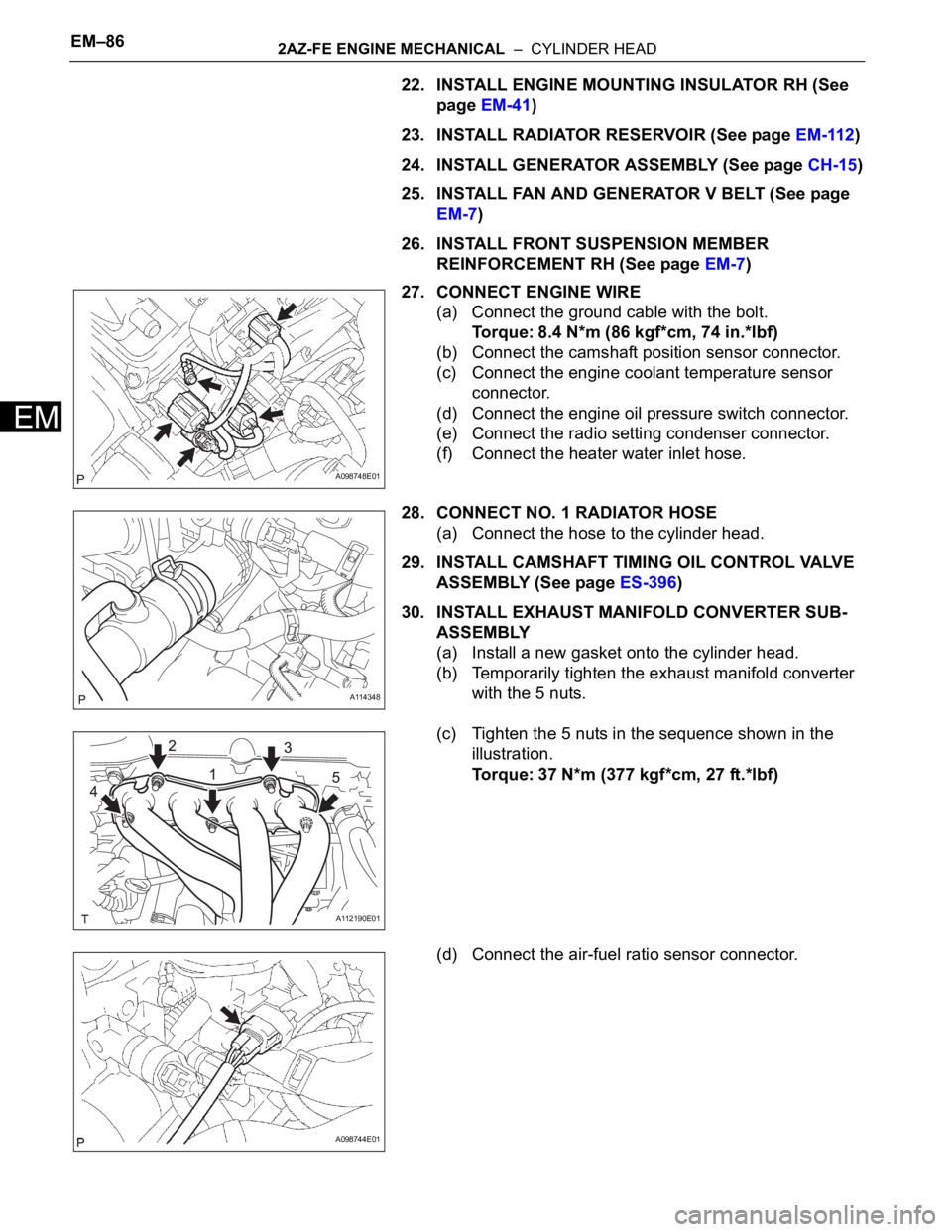
27. CONNECT ENGINE WIRE
(a) Connect the ground cable with the bolt.
Torque: 8.4 N*m (86 kgf*cm, 74 in.*lbf)
(b) Connect the camshaft position sensor connector.
(c) Connect the engine coolant temperature sensor
connector.
(d) Connect the engine oil pressure switch connector.
(e) Connect the radio setting condenser connector.
(f) Connect the heater water inlet hose.
28. CONNECT NO. 1 RADIATOR HOSE
(a) Connect the hose to the cylinder head.
29. INSTALL CAMSHAFT TIMING OIL CONTROL VALVE
ASSEMBLY (See page ES-396)
30. INSTALL EXHAUST MANIFOLD CONVERTER SUB-
ASSEMBLY
(a) Install a new gasket onto the cylinder head.
(b) Temporarily tighten the exhaust manifold converter
with the 5 nuts.
(c) Tighten the 5 nuts in the sequence shown in the
illustration.
Torque: 37 N*m (377 kgf*cm, 27 ft.*lbf)
(d) Connect the air-fuel ratio sensor connector.
A098748E01
A114348
A112190E01
A098744E01
Page 646 of 2000
2AZ-FE ENGINE MECHANICAL – ENGINE ASSEMBLYEM–111
EM
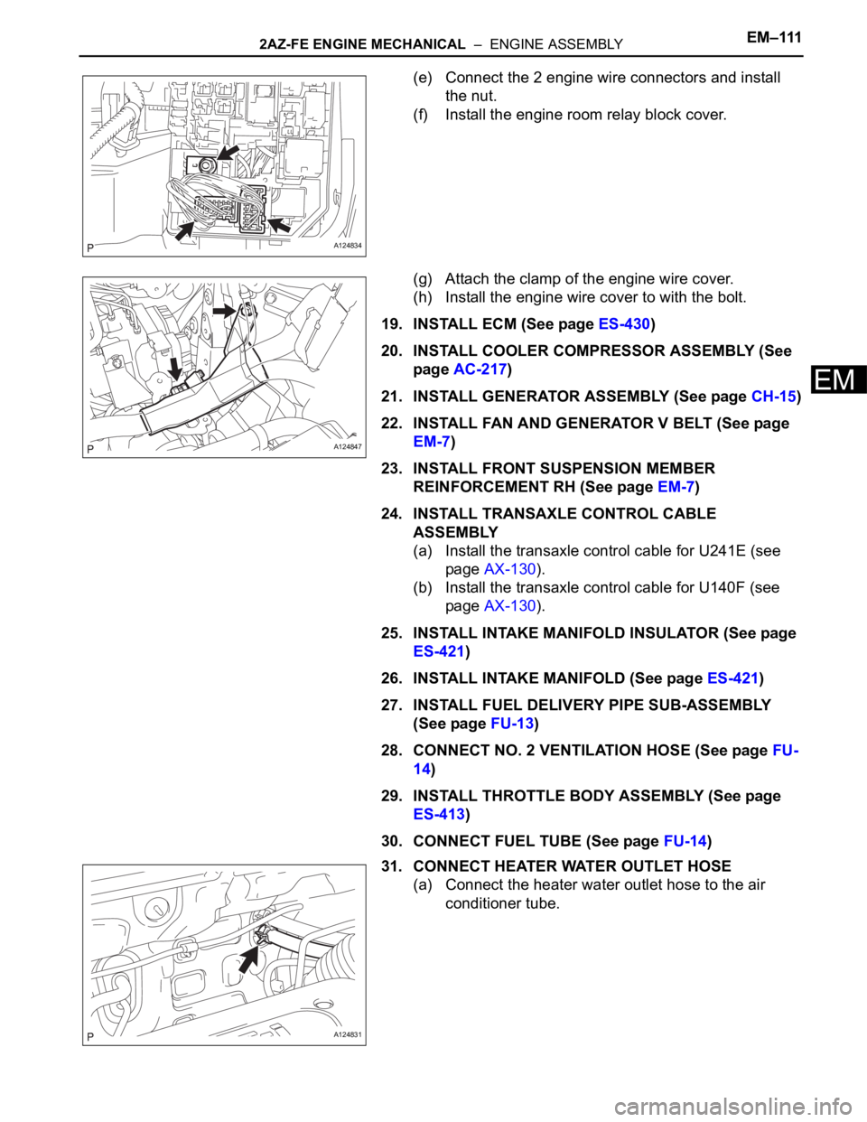
(e) Connect the 2 engine wire connectors and install
the nut.
(f) Install the engine room relay block cover.
(g) Attach the clamp of the engine wire cover.
(h) Install the engine wire cover to with the bolt.
19. INSTALL ECM (See page ES-430)
20. INSTALL COOLER COMPRESSOR ASSEMBLY (See
page AC-217)
21. INSTALL GENERATOR ASSEMBLY (See page CH-15)
22. INSTALL FAN AND GENERATOR V BELT (See page
EM-7)
23. INSTALL FRONT SUSPENSION MEMBER
REINFORCEMENT RH (See page EM-7)
24. INSTALL TRANSAXLE CONTROL CABLE
ASSEMBLY
(a) Install the transaxle control cable for U241E (see
page AX-130).
(b) Install the transaxle control cable for U140F (see
page AX-130).
25. INSTALL INTAKE MANIFOLD INSULATOR (See page
ES-421)
26. INSTALL INTAKE MANIFOLD (See page ES-421)
27. INSTALL FUEL DELIVERY PIPE SUB-ASSEMBLY
(See page FU-13)
28. CONNECT NO. 2 VENTILATION HOSE (See page FU-
14)
29. INSTALL THROTTLE BODY ASSEMBLY (See page
ES-413)
30. CONNECT FUEL TUBE (See page FU-14)
31. CONNECT HEATER WATER OUTLET HOSE
(a) Connect the heater water outlet hose to the air
conditioner tube.
A124834
A124847
A124831
Page 841 of 2000
2AZ-FE COOLING – WATER PUMPCO–11
CO
REMOVAL
1. DISCONNECT CABLE FROM NEGATIVE BATTERY
TERMINAL
CAUTION:
Wait at least 90 seconds after disconnecting the
cable from the negative (-) battery terminal to
prevent airbag and seat belt pretensioner activation.
2. REMOVE NO. 1 ENGINE UNDER COVER
3. REMOVE FRONT FENDER APRON RH
4. REMOVE RADIATOR SUPPORT OPENING COVER
5. DRAIN ENGINE COOLANT (See page CO-6)
6. REMOVE FRONT SUSPENSION MEMBER
REINFORCEMENT RH (See page EM-6)
7. REMOVE FAN AND GENERATOR V BELT (See page
EM-6)
8. REMOVE GENERATOR ASSEMBLY (See page CH-9)
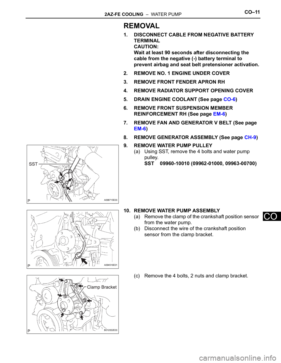
9. REMOVE WATER PUMP PULLEY
(a) Using SST, remove the 4 bolts and water pump
pulley.
SST 09960-10010 (09962-01000, 09963-00700)
10. REMOVE WATER PUMP ASSEMBLY
(a) Remove the clamp of the crankshaft position sensor
from the water pump.
(b) Disconnect the wire of the crankshaft position
sensor from the clamp bracket.
(c) Remove the 4 bolts, 2 nuts and clamp bracket.
A098715E03
A094516E01
B012052E03
Page 1450 of 2000
AXLE – FRONT AXLE HUBAH–9
AH
REMOVAL
(2006/01- )
HINT:
• Use the same procedures for the RH side and LH side.
• The procedures listed below are the LH side.
1. REMOVE FRONT WHEEL
2. DRAIN AUTOMATIC TRANSAXLE FLUID
(a) Drain the automatic transaxle fluid for U140F (see
page AX-147).
(b) Drain the automatic transaxle fluid for U241E (see
page AX-146).
(c) Drain the automatic transaxle fluid for U151E (see
page AX-172).
(d) Drain the automatic transaxle fluid for U151F (see
page AX-173).
3. DISCONNECT CABLE FROM NEGATIVE BATTERY
TERMINAL
CAUTION:
Wait at least 90 seconds after disconnecting the
cable from the negative (-) battery terminal to
prevent airbag and seat belt pretensioner activation.
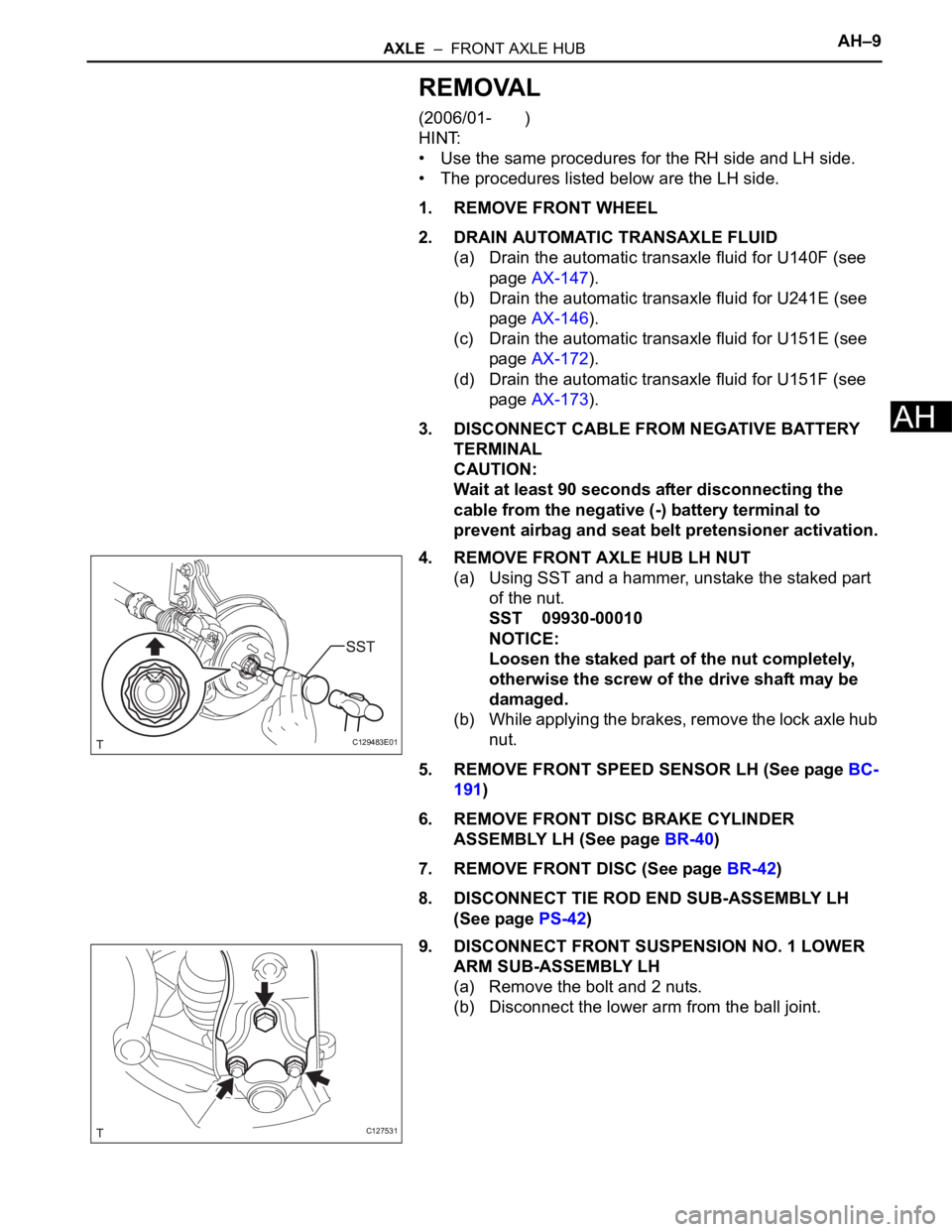
4. REMOVE FRONT AXLE HUB LH NUT
(a) Using SST and a hammer, unstake the staked part
of the nut.
SST 09930-00010
NOTICE:
Loosen the staked part of the nut completely,
otherwise the screw of the drive shaft may be
damaged.
(b) While applying the brakes, remove the lock axle hub
nut.
5. REMOVE FRONT SPEED SENSOR LH (See page BC-
191)
6. REMOVE FRONT DISC BRAKE CYLINDER
ASSEMBLY LH (See page BR-40)
7. REMOVE FRONT DISC (See page BR-42)
8. DISCONNECT TIE ROD END SUB-ASSEMBLY LH
(See page PS-42)
9. DISCONNECT FRONT SUSPENSION NO. 1 LOWER
ARM SUB-ASSEMBLY LH
(a) Remove the bolt and 2 nuts.
(b) Disconnect the lower arm from the ball joint.
C129483E01
C127531
Page 1457 of 2000
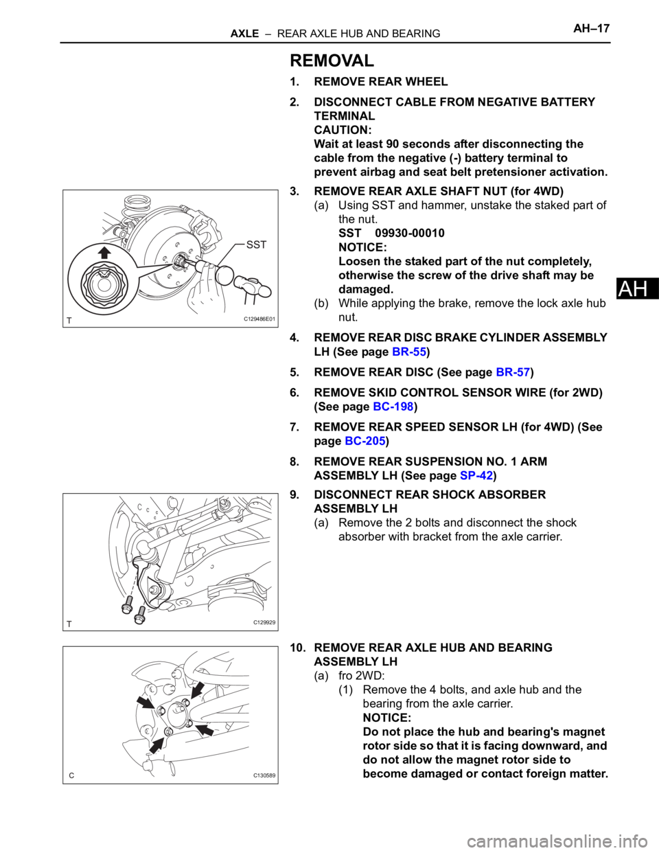
AXLE – REAR AXLE HUB AND BEARINGAH–17
AH
REMOVAL
1. REMOVE REAR WHEEL
2. DISCONNECT CABLE FROM NEGATIVE BATTERY
TERMINAL
CAUTION:
Wait at least 90 seconds after disconnecting the
cable from the negative (-) battery terminal to
prevent airbag and seat belt pretensioner activation.
3. REMOVE REAR AXLE SHAFT NUT (for 4WD)
(a) Using SST and hammer, unstake the staked part of
the nut.
SST 09930-00010
NOTICE:
Loosen the staked part of the nut completely,
otherwise the screw of the drive shaft may be
damaged.
(b) While applying the brake, remove the lock axle hub
nut.
4. REMOVE REAR DISC BRAKE CYLINDER ASSEMBLY
LH (See page BR-55)
5. REMOVE REAR DISC (See page BR-57)
6. REMOVE SKID CONTROL SENSOR WIRE (for 2WD)
(See page BC-198)
7. REMOVE REAR SPEED SENSOR LH (for 4WD) (See
page BC-205)
8. REMOVE REAR SUSPENSION NO. 1 ARM
ASSEMBLY LH (See page SP-42)
9. DISCONNECT REAR SHOCK ABSORBER
ASSEMBLY LH
(a) Remove the 2 bolts and disconnect the shock
absorber with bracket from the axle carrier.
10. REMOVE REAR AXLE HUB AND BEARING
ASSEMBLY LH
(a) fro 2WD:
(1) Remove the 4 bolts, and axle hub and the
bearing from the axle carrier.
NOTICE:
Do not place the hub and bearing's magnet
rotor side so that it is facing downward, and
do not allow the magnet rotor side to
become damaged or contact foreign matter.
C129486E01
C129929
C130589