parking TOYOTA RAV4 2006 Service Workshop Manual
[x] Cancel search | Manufacturer: TOYOTA, Model Year: 2006, Model line: RAV4, Model: TOYOTA RAV4 2006Pages: 2000, PDF Size: 45.84 MB
Page 1275 of 2000

U241E AUTOMATIC TRANSAXLE – AUTOMATIC TRANSAXLE UNITAX–171
AX
24. REMOVE MANUAL VALVE LEVER SUB-ASSEMBLY
(a) Using a chisel and hammer, unstake and remove
the manual valve lever spacer.
(b) Using a pin punch and hammer, tap out the manual
valve lever shaft spring pin.
HINT:
Slowly drive out the pin so that it will not fall into the
transaxle.
(c) Remove the manual valve lever shaft and manual
valve lever.
25. REMOVE PARKING LOCK ROD SUB-ASSEMBLY
(a) Remove the parking lock rod from the manual valve
lever.
26. REMOVE MANUAL VALVE LEVER SHAFT OIL SEAL
(a) Using a screwdriver, pry out the oil seal from the
transaxle.
27. INSPECT INPUT SHAFT END PLAY (See page AX-
185)
D003563E01
D003564E01
D003565E02
D003905E01
D003566E02
Page 1278 of 2000

AX–174U241E AUTOMATIC TRANSAXLE – AUTOMATIC TRANSAXLE UNIT
AX
(b) Remove the thrust bearing from the forward clutch.
38. REMOVE MULTIPLE DISC CLUTCH CLUTCH HUB
(a) Remove the thrust bearing, multiple clutch hub,
needle roller bearing and bearing race from the
transaxle.
39. REMOVE UNDERDRIVE PLANETARY GEAR
ASSEMBLY
(a) Remove the bolt and parking pawl shaft clamp.
(b) Remove the parking lock pawl shaft.
(c) Push the parking lock pawl.
HINT:
Failure to do so will cause the interference when the
underdrive planetary gear is removed.
D003906E02
D003575E01
D003576E03
D009201E01
D008048E01
Page 1279 of 2000

U241E AUTOMATIC TRANSAXLE – AUTOMATIC TRANSAXLE UNITAX–175
AX
(d) Remove the underdrive planetary gear from the
transaxle.
NOTICE:
Be careful so that the underdrive planetary gear
assembly will not fall out.
(e) Remove the spring, pawl pin and parking lock pawl.
40. REMOVE UNDERDRIVE CLUTCH ASSEMBLY
(a) Remove the underdrive clutch assembly, needle
roller bearing, thrust bearing underdrive race from
the transaxle.
41. REMOVE UNDERDRIVE 1-WAY CLUTCH ASSEMBLY
(a) Using a screwdriver, pry out the snap ring from the
transaxle.
(b) Remove the 1-way clutch from the transaxle.
D003579E04
D008049E01
D003580E02
D003581E02
D003627E03
Page 1307 of 2000

U241E AUTOMATIC TRANSAXLE – AUTOMATIC TRANSAXLE UNITAX–203
AX
(b) Install the underdrive clutch assembly to the 1-way
clutch. Rotate the underdrive clutch to check the
rotating direction for the lock or free operation.
(c) Install the 1-way clutch to the transaxle.
NOTICE:
Make sure that the mark on the 1-way clutch
outer race is visible.
(d) Using a screwdriver, install the snap ring to the
transaxle.
28. INSTALL UNDERDRIVE CLUTCH
(a) Coat the bearing and bearing race with petroleum
jelly, and install them onto the underdrive clutch.
Standard race diameter
(b) Install the underdrive clutch assembly to the
transaxle.
29. INSTALL UNDERDRIVE PLANETARY GEAR
ASSEMBLY
(a) Install the parking lock pawl pin and torsion spring to
the parking lock pawl.
D003925E02
C050158E01
D003581E02
D003580E02
Item Inside Outside
Bearing 37.73 mm (1.4854 in.) 58.0 mm (2.283 in.)
Race 29.9 mm (1.177 in.) 55.5 mm (2.185 in.)
D009691E02
Page 1308 of 2000
AX–204U241E AUTOMATIC TRANSAXLE – AUTOMATIC TRANSAXLE UNIT
AX
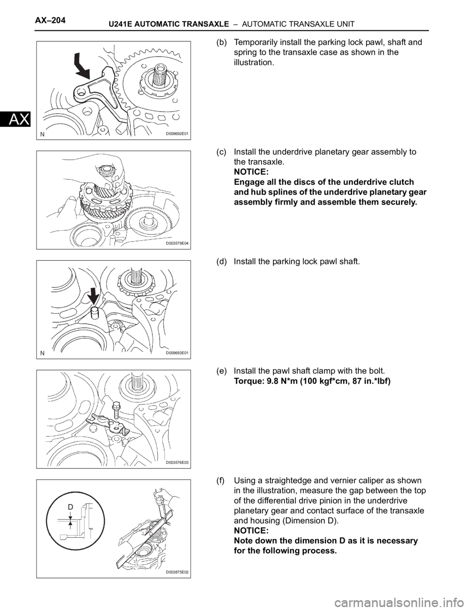
(b) Temporarily install the parking lock pawl, shaft and
spring to the transaxle case as shown in the
illustration.
(c) Install the underdrive planetary gear assembly to
the transaxle.
NOTICE:
Engage all the discs of the underdrive clutch
and hub splines of the underdrive planetary gear
assembly firmly and assemble them securely.
(d) Install the parking lock pawl shaft.
(e) Install the pawl shaft clamp with the bolt.
Torque: 9.8 N*m (100 kgf*cm, 87 in.*lbf)
(f) Using a straightedge and vernier caliper as shown
in the illustration, measure the gap between the top
of the differential drive pinion in the underdrive
planetary gear and contact surface of the transaxle
and housing (Dimension D).
NOTICE:
Note down the dimension D as it is necessary
for the following process.
D009692E01
D003579E04
D009693E01
D003576E03
D003875E02
Page 1313 of 2000
U241E AUTOMATIC TRANSAXLE – AUTOMATIC TRANSAXLE UNITAX–209
AX
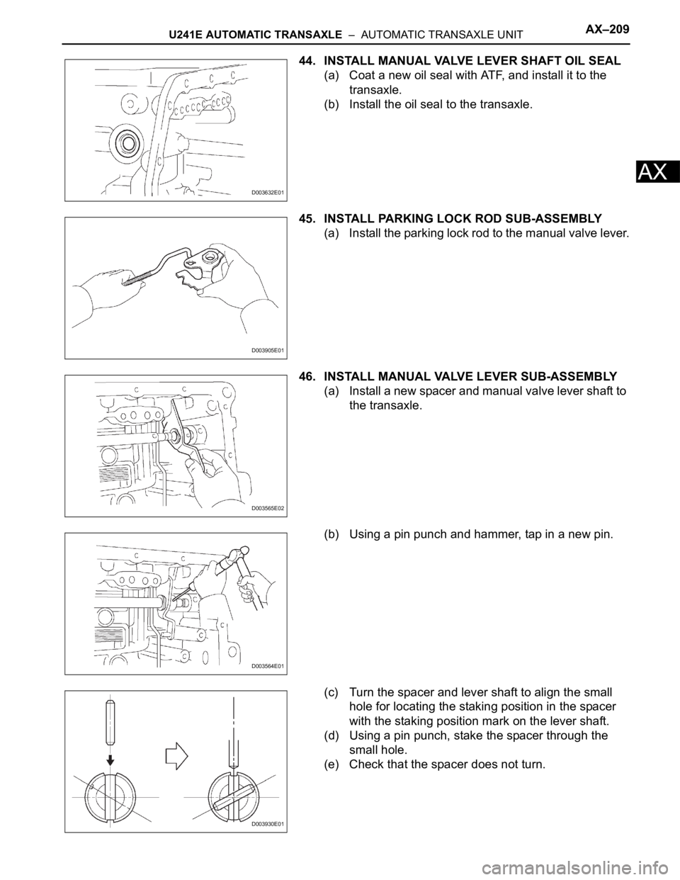
44. INSTALL MANUAL VALVE LEVER SHAFT OIL SEAL
(a) Coat a new oil seal with ATF, and install it to the
transaxle.
(b) Install the oil seal to the transaxle.
45. INSTALL PARKING LOCK ROD SUB-ASSEMBLY
(a) Install the parking lock rod to the manual valve lever.
46. INSTALL MANUAL VALVE LEVER SUB-ASSEMBLY
(a) Install a new spacer and manual valve lever shaft to
the transaxle.
(b) Using a pin punch and hammer, tap in a new pin.
(c) Turn the spacer and lever shaft to align the small
hole for locating the staking position in the spacer
with the staking position mark on the lever shaft.
(d) Using a pin punch, stake the spacer through the
small hole.
(e) Check that the spacer does not turn.
D003632E01
D003905E01
D003565E02
D003564E01
D003930E01
Page 1314 of 2000
AX–210U241E AUTOMATIC TRANSAXLE – AUTOMATIC TRANSAXLE UNIT
AX
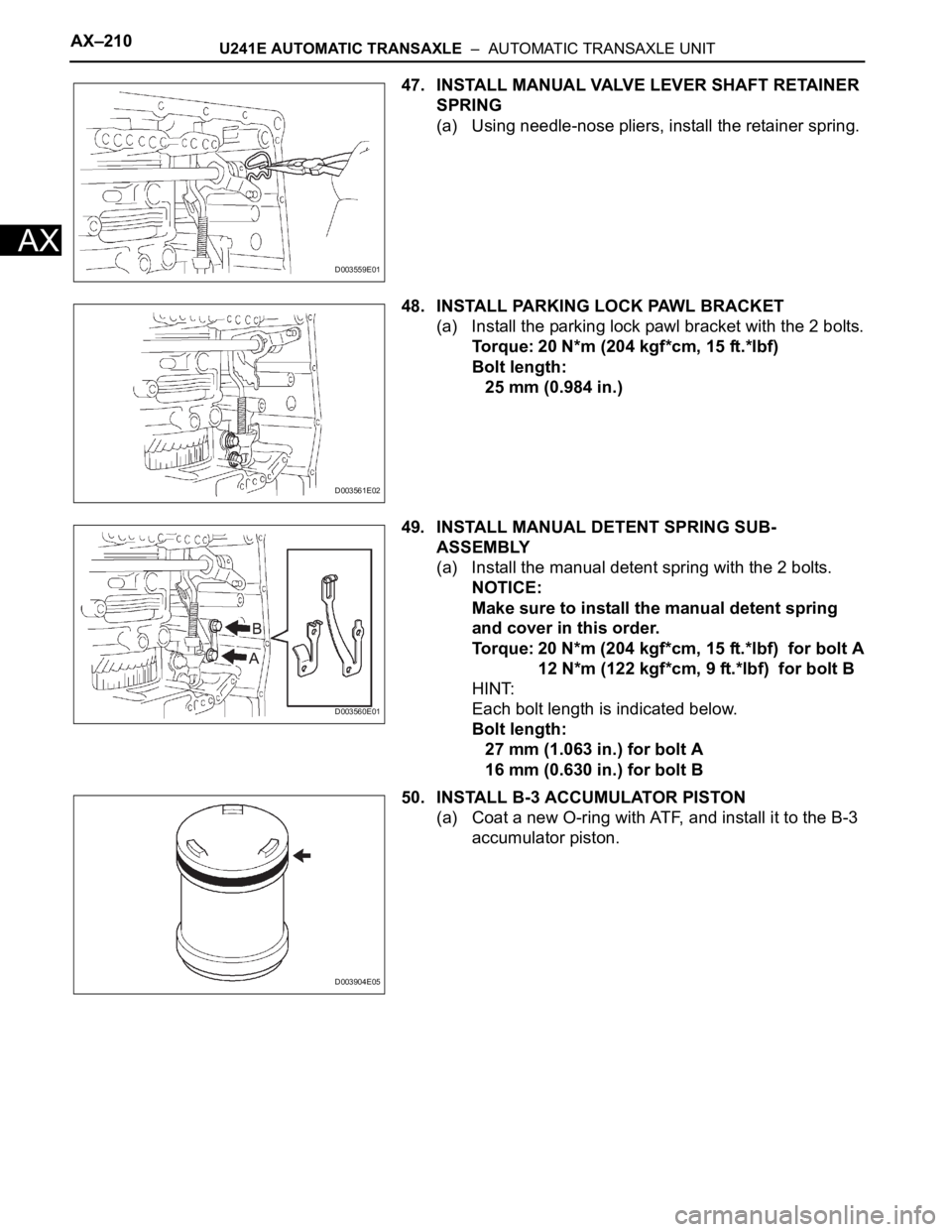
47. INSTALL MANUAL VALVE LEVER SHAFT RETAINER
SPRING
(a) Using needle-nose pliers, install the retainer spring.
48. INSTALL PARKING LOCK PAWL BRACKET
(a) Install the parking lock pawl bracket with the 2 bolts.
Torque: 20 N*m (204 kgf*cm, 15 ft.*lbf)
Bolt length:
25 mm (0.984 in.)
49. INSTALL MANUAL DETENT SPRING SUB-
ASSEMBLY
(a) Install the manual detent spring with the 2 bolts.
NOTICE:
Make sure to install the manual detent spring
and cover in this order.
Torque: 20 N*m (204 kgf*cm, 15 ft.*lbf) for bolt A
12 N*m (122 kgf*cm, 9 ft.*lbf) for bolt B
HINT:
Each bolt length is indicated below.
Bolt length:
27 mm (1.063 in.) for bolt A
16 mm (0.630 in.) for bolt B
50. INSTALL B-3 ACCUMULATOR PISTON
(a) Coat a new O-ring with ATF, and install it to the B-3
accumulator piston.
D003559E01
D003561E02
D003560E01
D003904E05
Page 1470 of 2000
SP–34SUSPENSION – REAR COIL SPRING
SP
INSTALLATION
HINT:
• Use the same procedures for the RH side and LH side.
• The procedures listed below are for the LH side.
1. INSTALL REAR COIL SPRING INSULATOR LOWER
LH
(a) Install the insulator lower to the suspension No. 2
arm.
2. REMOVE REAR COIL SPRING LH
(a) Install the coil spring to the suspension No. 2 arm.
3. INSTALL REAR COIL SPRING INSULATOR UPPER
LH
(a) Align the stopper part of the insulator upper with the
coil spring tip, and install the insulator upper.
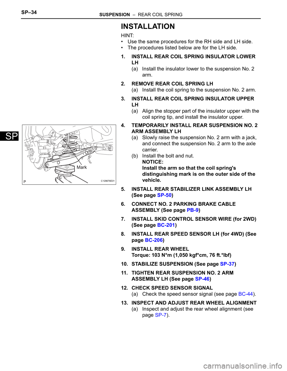
4. TEMPORARILY INSTALL REAR SUSPENSION NO. 2
ARM ASSEMBLY LH
(a) Slowly raise the suspension No. 2 arm with a jack,
and connect the suspension No. 2 arm to the axle
carrier.
(b) Install the bolt and nut.
NOTICE:
Install the arm so that the coil spring's
distinguishing mark is on the outer side of the
vehicle.
5. INSTALL REAR STABILIZER LINK ASSEMBLY LH
(See page SP-50)
6. CONNECT NO. 2 PARKING BRAKE CABLE
ASSEMBLY (See page PB-9)
7. INSTALL SKID CONTROL SENSOR WIRE (for 2WD)
(See page BC-201)
8. INSTALL REAR SPEED SENSOR LH (for 4WD) (See
page BC-206)
9. INSTALL REAR WHEEL
Torque: 103 N*m (1,050 kgf*cm, 76 ft.*lbf)
10. STABILIZE SUSPENSION (See page SP-37)
11. TIGHTEN REAR SUSPENSION NO. 2 ARM
ASSEMBLY LH (See page SP-46)
12. CHECK SPEED SENSOR SIGNAL
(a) Check the speed sensor signal (see page BC-44).
13. INSPECT AND ADJUST REAR WHEEL ALIGNMENT
(a) Inspect and adjust the rear wheel alignment (see
page SP-7).
C129676E01
Page 1473 of 2000
SUSPENSION – REAR NO. 2 SUSPENSION ARMSP–47
SP
INSTALLATION
HINT:
• Use the same procedures for the RH side and LH side.
• The procedures listed below are for the LH side.
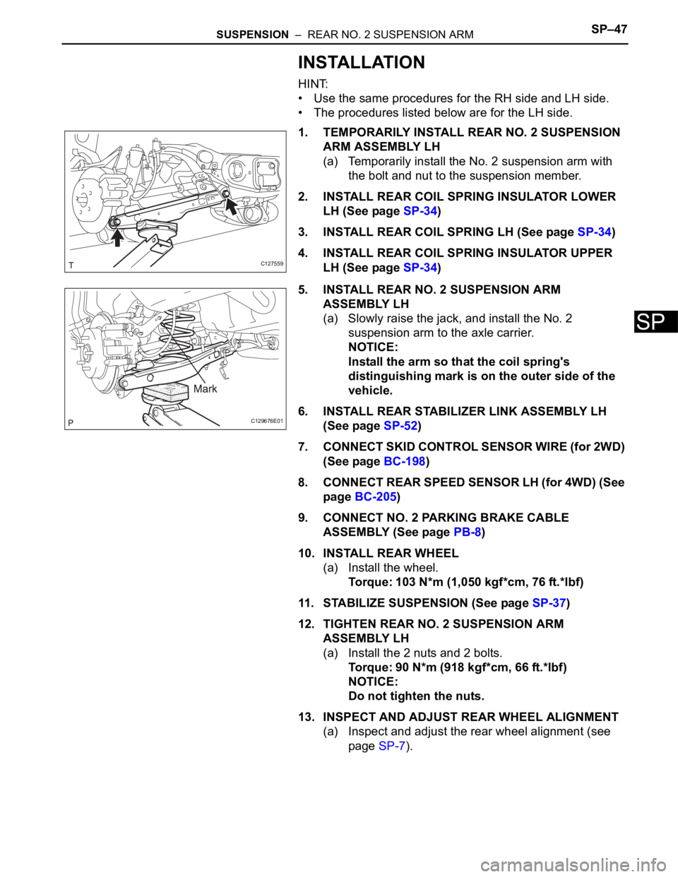
1. TEMPORARILY INSTALL REAR NO. 2 SUSPENSION
ARM ASSEMBLY LH
(a) Temporarily install the No. 2 suspension arm with
the bolt and nut to the suspension member.
2. INSTALL REAR COIL SPRING INSULATOR LOWER
LH (See page SP-34)
3. INSTALL REAR COIL SPRING LH (See page SP-34)
4. INSTALL REAR COIL SPRING INSULATOR UPPER
LH (See page SP-34)
5. INSTALL REAR NO. 2 SUSPENSION ARM
ASSEMBLY LH
(a) Slowly raise the jack, and install the No. 2
suspension arm to the axle carrier.
NOTICE:
Install the arm so that the coil spring's
distinguishing mark is on the outer side of the
vehicle.
6. INSTALL REAR STABILIZER LINK ASSEMBLY LH
(See page SP-52)
7. CONNECT SKID CONTROL SENSOR WIRE (for 2WD)
(See page BC-198)
8. CONNECT REAR SPEED SENSOR LH (for 4WD) (See
page BC-205)
9. CONNECT NO. 2 PARKING BRAKE CABLE
ASSEMBLY (See page PB-8)
10. INSTALL REAR WHEEL
(a) Install the wheel.
Torque: 103 N*m (1,050 kgf*cm, 76 ft.*lbf)
11. STABILIZE SUSPENSION (See page SP-37)
12. TIGHTEN REAR NO. 2 SUSPENSION ARM
ASSEMBLY LH
(a) Install the 2 nuts and 2 bolts.
Torque: 90 N*m (918 kgf*cm, 66 ft.*lbf)
NOTICE:
Do not tighten the nuts.
13. INSPECT AND ADJUST REAR WHEEL ALIGNMENT
(a) Inspect and adjust the rear wheel alignment (see
page SP-7).
C127559
C129676E01
Page 1474 of 2000
SUSPENSION – REAR TRAILING ARMSP–49
SP
INSTALLATION
HINT:
• Use the same procedures for the RH side and LH side.
• The procedures listed below are for the LH side.
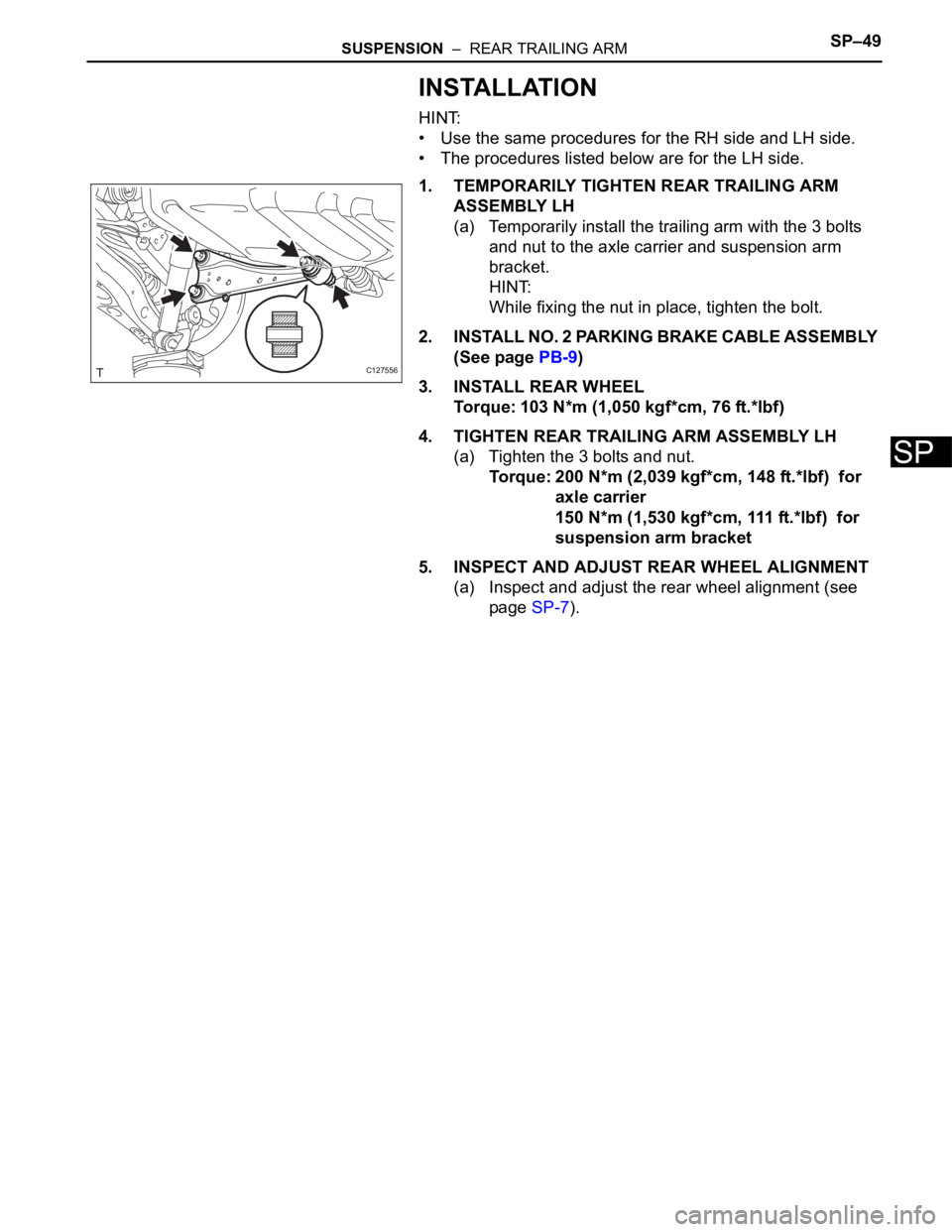
1. TEMPORARILY TIGHTEN REAR TRAILING ARM
ASSEMBLY LH
(a) Temporarily install the trailing arm with the 3 bolts
and nut to the axle carrier and suspension arm
bracket.
HINT:
While fixing the nut in place, tighten the bolt.
2. INSTALL NO. 2 PARKING BRAKE CABLE ASSEMBLY
(See page PB-9)
3. INSTALL REAR WHEEL
Torque: 103 N*m (1,050 kgf*cm, 76 ft.*lbf)
4. TIGHTEN REAR TRAILING ARM ASSEMBLY LH
(a) Tighten the 3 bolts and nut.
Torque: 200 N*m (2,039 kgf*cm, 148 ft.*lbf) for
axle carrier
150 N*m (1,530 kgf*cm, 111 ft.*lbf) for
suspension arm bracket
5. INSPECT AND ADJUST REAR WHEEL ALIGNMENT
(a) Inspect and adjust the rear wheel alignment (see
page SP-7).
C127556